User Manual
Page 3
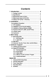
... BIOS Setup Menu 24 2. Contents 1 Introduction 4 1.1 Package Contents 4 1.2 Specifications 5 1.3 Motherboard Layout (K7S41 7 1.4 Motherboard Layout (K7S41GX 8 1.5 ASRock I/OTM (K7S41 / K7S41GX 9 2 Installation 10 Pre-installation Precautions 10 2.1 CPU Installation 11 2.2 Installation of CPU Fan and..., Power, Boot, and Exit Menus ...... 22 4 Software Support 23 4.1 Installing Operating System 23 4.2 Support CD Information 23 4.2.1 Running Support CD 23 4.2.2 Drivers Menu 23 4.2.3 Utilities Menu 23 4.2.4 ASRock "PC-DIY Live Demo" Program 23 4.2.5 Contact Information 23...
... BIOS Setup Menu 24 2. Contents 1 Introduction 4 1.1 Package Contents 4 1.2 Specifications 5 1.3 Motherboard Layout (K7S41 7 1.4 Motherboard Layout (K7S41GX 8 1.5 ASRock I/OTM (K7S41 / K7S41GX 9 2 Installation 10 Pre-installation Precautions 10 2.1 CPU Installation 11 2.2 Installation of CPU Fan and..., Power, Boot, and Exit Menus ...... 22 4 Software Support 23 4.1 Installing Operating System 23 4.2 Support CD Information 23 4.2.1 Running Support CD 23 4.2.2 Drivers Menu 23 4.2.3 Utilities Menu 23 4.2.4 ASRock "PC-DIY Live Demo" Program 23 4.2.5 Contact Information 23...

User Manual
Page 4
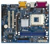
... may find the latest memory and CPU support lists on ASRock website without notice. Chapter 1 Introduction Thank you for advanced users' reference. ASRock website http://www.asrock.com 1.1 Package Contents ASRock K7S41 or K7S41GX Motherboard (Micro ATX Form Factor: 9.6-in x 7.8-in, 24.4 cm x 19.8 cm) ASRock K7S41 / K7S41GX Quick Installation Guide ASRock K7S41 / K7S41GX Support CD One 80-conductor Ultra ATA...
... may find the latest memory and CPU support lists on ASRock website without notice. Chapter 1 Introduction Thank you for advanced users' reference. ASRock website http://www.asrock.com 1.1 Package Contents ASRock K7S41 or K7S41GX Motherboard (Micro ATX Form Factor: 9.6-in x 7.8-in, 24.4 cm x 19.8 cm) ASRock K7S41 / K7S41GX Quick Installation Guide ASRock K7S41 / K7S41GX Support CD One 80-conductor Ultra ATA...

User Manual
Page 6
... a 3.3V AGP card on the motherboard functions properly before you install the PC system. 2. BIOS: OS: AMI legal BIOS, "Plug and Play" support, ACPI 1.1 compliance wake up events, SMBIOS 2.3.1 support, CPU frequency stepless control (only for advanced users' reference, see CAUTION 4) Microsoft® Windows® 98 SE / ME / 2000 / XP compliant CAUTION...
... a 3.3V AGP card on the motherboard functions properly before you install the PC system. 2. BIOS: OS: AMI legal BIOS, "Plug and Play" support, ACPI 1.1 compliance wake up events, SMBIOS 2.3.1 support, CPU frequency stepless control (only for advanced users' reference, see CAUTION 4) Microsoft® Windows® 98 SE / ME / 2000 / XP compliant CAUTION...

User Manual
Page 11
... sure that it is in place, press it fits in place. The lever clicks on the socket while you push down the socket lever to support AMD Athlon XP / Duron CPU. Lever 90° Up STEP 1: Lift Up The Socket Lever Socket Marked Corner CPU Marked Corner STEP 2/STEP 3: STEP 4: Match...
... sure that it is in place, press it fits in place. The lever clicks on the socket while you push down the socket lever to support AMD Athlon XP / Duron CPU. Lever 90° Up STEP 1: Lift Up The Socket Lever Socket Marked Corner CPU Marked Corner STEP 2/STEP 3: STEP 4: Match...
User Manual
Page 16
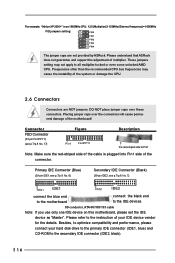
Placing jumper caps over these connectors. Please understand that ASRock does not guarantee and support the adjustment of the motherboard! DO NOT place jumper caps over the connectors will cause permanent damage of multiplier. Besides, to optimize compatibility and performance, ... AMD CPU. For example, "Athlon XP 2000+" is plugged into Pin1 side of the system or damage the CPU. 2.6 Connectors Connectors are not provided by ASRock.
Placing jumper caps over these connectors. Please understand that ASRock does not guarantee and support the adjustment of the motherboard! DO NOT place jumper caps over the connectors will cause permanent damage of multiplier. Besides, to optimize compatibility and performance, ... AMD CPU. For example, "Athlon XP 2000+" is plugged into Pin1 side of the system or damage the CPU. 2.6 Connectors Connectors are not provided by ASRock.

User Manual
Page 17
...25) System Panel Connector (9-pin PANEL1) (see p.7/p.8 No. 15) Chassis Speaker Connector (4-pin SPEAKER 1) (see p.7/p.8 No. 19) IRTX +5V DUMMY 1 GND IRRX This connector supports an optional wireless transmitting and receiving infrared module. O U T- PLED+ PLEDPWRBTN# GND 1 DUMMY RESET# GND HDLEDHDLED+ This connector accommodates several system front panel functions. 1 SPEAKER DUMMY...see p.7/p.8 No. 28) (AUX1: see p.7/p.8 No. 18) USB_PWR P-5 P+5 GND DUMMY 1 GND P+4 P-4 USB_PWR There are not sufficient, this connector and match the black wire to support 2 additional USB 2.0 ports.
...25) System Panel Connector (9-pin PANEL1) (see p.7/p.8 No. 15) Chassis Speaker Connector (4-pin SPEAKER 1) (see p.7/p.8 No. 19) IRTX +5V DUMMY 1 GND IRRX This connector supports an optional wireless transmitting and receiving infrared module. O U T- PLED+ PLEDPWRBTN# GND 1 DUMMY RESET# GND HDLEDHDLED+ This connector accommodates several system front panel functions. 1 SPEAKER DUMMY...see p.7/p.8 No. 28) (AUX1: see p.7/p.8 No. 18) USB_PWR P-5 P+5 GND DUMMY 1 GND P+4 P-4 USB_PWR There are not sufficient, this connector and match the black wire to support 2 additional USB 2.0 ports.
User Manual
Page 18
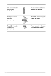
Please connect a 3-pin power LED cable to this connector. 18 Serial port connector (9-pin COM1) (see p.7/p.8 No. 22) Power LED Connector (3-pin PWR_LED1) (see p.7/p.8 No. 6) Please connect an ATX power supply to this connector. ATX Power Connector (20-pin ATXPWR1) (see p.7/p.8 No. 14) RRXD1 DDTR#1 DDSR#1 CCTS#1 1 RRI#1 RRTS#1 GND TTXD1 DDCD#1 1 PLED- PLED+ PLED+ This COM1 connector supports a serial port module.
Please connect a 3-pin power LED cable to this connector. 18 Serial port connector (9-pin COM1) (see p.7/p.8 No. 22) Power LED Connector (3-pin PWR_LED1) (see p.7/p.8 No. 6) Please connect an ATX power supply to this connector. ATX Power Connector (20-pin ATXPWR1) (see p.7/p.8 No. 14) RRXD1 DDTR#1 DDSR#1 CCTS#1 1 RRI#1 RRTS#1 GND TTXD1 DDCD#1 1 PLED- PLED+ PLED+ This COM1 connector supports a serial port module.

User Manual
Page 23
... PC-DIY live demo, which shows you how to visit ASRock's website at http://www.asrock.com; Click on the file ASSETUP.EXE from the BIN folder in the Support CD to know more information. 4.2 Support CD Information The Support CD that came with the motherboard contains necessary drivers and useful...shows the applications software that will enhance the motherboard features. 4.2.1 Running The Support CD To begin using the support CD, insert the CD into your own PC system step by step. or you need to contact ASRock or want to display the menus. 4.2.2 Drivers Menu The Drivers Menu ...
... PC-DIY live demo, which shows you how to visit ASRock's website at http://www.asrock.com; Click on the file ASSETUP.EXE from the BIN folder in the Support CD to know more information. 4.2 Support CD Information The Support CD that came with the motherboard contains necessary drivers and useful...shows the applications software that will enhance the motherboard features. 4.2.1 Running The Support CD To begin using the support CD, insert the CD into your own PC system step by step. or you need to contact ASRock or want to display the menus. 4.2.2 Drivers Menu The Drivers Menu ...

User Manual
Page 25
... It is [Disabled]. USB Controller: Use this is used for onboard VGA. Please note that not all the DDR DIMMs can support CAS latency=3T. VERSION 3.31a Chipset Configuration [ Setup Help ] Onboard VGA Share Memory AGP Aperture Size USB Controller USB 2.0 Controller USB Device... Legacy Support DRAM CAS Latency Over Vcore Voltage Auto 64M Enabled Enabled Disabled Auto Disabled to enable or disable the use of memory accessing. Chipset...
... It is [Disabled]. USB Controller: Use this is used for onboard VGA. Please note that not all the DDR DIMMs can support CAS latency=3T. VERSION 3.31a Chipset Configuration [ Setup Help ] Onboard VGA Share Memory AGP Aperture Size USB Controller USB 2.0 Controller USB Device... Legacy Support DRAM CAS Latency Over Vcore Voltage Auto 64M Enabled Enabled Disabled Auto Disabled to enable or disable the use of memory accessing. Chipset...

User Manual
Page 26
... Auto Auto Disabled Auto ECP+EPP 1.9 Auto Auto Disabled 5 200 Both Enabled Auto Auto to enable or disable the feature of AGP fast write protocol support. Leave on the mother board, you to enable or disable the floppy drive controller. Primary Graphics Adapter: If both AGPcard and PCI graphics card are...
... Auto Auto Disabled Auto ECP+EPP 1.9 Auto Auto Disabled 5 200 Both Enabled Auto Auto to enable or disable the feature of AGP fast write protocol support. Leave on the mother board, you to enable or disable the floppy drive controller. Primary Graphics Adapter: If both AGPcard and PCI graphics card are...
User Manual
Page 29
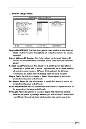
... or disable the ACPI S3 feature. PCI Devices Power On: Use this to enable or disable PS/2 keyboard to enable this feature if the system supports it. Select [Auto] will enable this feature under Microsoft® Windows® 98 / ME. Restore on the system from the power-soft-off mode. PS...
... or disable the ACPI S3 feature. PCI Devices Power On: Use this to enable or disable PS/2 keyboard to enable this feature if the system supports it. Select [Auto] will enable this feature under Microsoft® Windows® 98 / ME. Restore on the system from the power-soft-off mode. PS...


