User Manual
Page 3
... 1 Introduction 4 1.1 Package Contents 4 1.2 Specifications 5 1.3 Motherboard Layout (K7S41 7 1.4 Motherboard Layout (K7S41GX 8 1.5 ASRock I/OTM (K7S41 / K7S41GX 9 2 Installation 10 Pre-installation Precautions 10 2.1 CPU Installation 11 2.2 Installation of CPU Fan and Heatsink 11 2.3 Installation of Memory Modules (DIMM 12 2.4 Expansion Slots (PCI, AMR, and AGP Slots 13...System 23 4.2 Support CD Information 23 4.2.1 Running Support CD 23 4.2.2 Drivers Menu 23 4.2.3 Utilities Menu 23 4.2.4 ASRock "PC-DIY Live Demo" Program 23 4.2.5 Contact Information 23 Appendix 24 1.
... 1 Introduction 4 1.1 Package Contents 4 1.2 Specifications 5 1.3 Motherboard Layout (K7S41 7 1.4 Motherboard Layout (K7S41GX 8 1.5 ASRock I/OTM (K7S41 / K7S41GX 9 2 Installation 10 Pre-installation Precautions 10 2.1 CPU Installation 11 2.2 Installation of CPU Fan and Heatsink 11 2.3 Installation of Memory Modules (DIMM 12 2.4 Expansion Slots (PCI, AMR, and AGP Slots 13...System 23 4.2 Support CD Information 23 4.2.1 Running Support CD 23 4.2.2 Drivers Menu 23 4.2.3 Utilities Menu 23 4.2.4 ASRock "PC-DIY Live Demo" Program 23 4.2.5 Contact Information 23 Appendix 24 1.

User Manual
Page 4
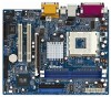
... without notice. You may find the latest memory and CPU support lists on page 24 for advanced users' reference. Chapter 1 Introduction Thank you for a 3.5-in Floppy Drive One ASRock I/OTM Shield One COM Port Bracket One ASRock MR Card (Optional) 4 ASRock website http://www.asrock.com 1.1 Package Contents ASRock K7S41 or K7S41GX Motherboard (Micro ATX Form Factor...
... without notice. You may find the latest memory and CPU support lists on page 24 for advanced users' reference. Chapter 1 Introduction Thank you for a 3.5-in Floppy Drive One ASRock I/OTM Shield One COM Port Bracket One ASRock MR Card (Optional) 4 ASRock website http://www.asrock.com 1.1 Package Contents ASRock K7S41 or K7S41GX Motherboard (Micro ATX Form Factor...
User Manual
Page 7
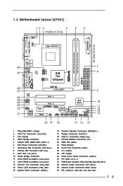
... FSB_SEL1 1 FSB_SEL0 SiS 741 Chipset AGP 8X 1.5V_AGP1 ` ATA133 IDE2 IDE1 AUDIO CODEC AUDIO1 1 JR1 JL1 COM1 1 2MB BIOS PCI 1 PCI 2 SiS 963L K7S41 Super I/O IR1 AMR1 1 FSB400 DDR400 USB45 1 CMOS CLRCMOS1 Battery 5.1CH CLRCMOS2 FLOPPY1 USB 2.0 CHA_FAN1 PWR_LED1 1 PLED PWRBTN SPEAKER1 PANEL 1 1 1 HDLED RST ... 1) 17 Floppy Connector (FLOPPY1) 18 USB 2.0 Connector (USB45, Blue) 19 Infrared Module Connector (IR1) 20 AMR Slot (AMR1) 21 Flash Memory 22 Serial Port Connector (COM1) 23 JL1 Jumper 24 JR1 Jumper 25 Front Panel Audio Connector (AUDIO1) 26 PCI Slots (PCI 1- 2) 27 ...
... FSB_SEL1 1 FSB_SEL0 SiS 741 Chipset AGP 8X 1.5V_AGP1 ` ATA133 IDE2 IDE1 AUDIO CODEC AUDIO1 1 JR1 JL1 COM1 1 2MB BIOS PCI 1 PCI 2 SiS 963L K7S41 Super I/O IR1 AMR1 1 FSB400 DDR400 USB45 1 CMOS CLRCMOS1 Battery 5.1CH CLRCMOS2 FLOPPY1 USB 2.0 CHA_FAN1 PWR_LED1 1 PLED PWRBTN SPEAKER1 PANEL 1 1 1 HDLED RST ... 1) 17 Floppy Connector (FLOPPY1) 18 USB 2.0 Connector (USB45, Blue) 19 Infrared Module Connector (IR1) 20 AMR Slot (AMR1) 21 Flash Memory 22 Serial Port Connector (COM1) 23 JL1 Jumper 24 JR1 Jumper 25 Front Panel Audio Connector (AUDIO1) 26 PCI Slots (PCI 1- 2) 27 ...
User Manual
Page 8
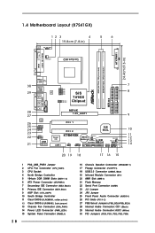
...) 8 16 Chassis Speaker Connector (SPEAKER 1) 17 Floppy Connector (FLOPPY1) 18 USB 2.0 Connector (USB45, Blue) 19 Infrared Module Connector (IR1) 20 AMR Slot (AMR1) 21 Flash Memory 22 Serial Port Connector (COM1) 23 JL1 Jumper 24 JR1 Jumper 25 Front Panel Audio Connector (AUDIO1) 26 PCI Slots (PCI 1- 2) 27 FSB Select Jumpers...
...) 8 16 Chassis Speaker Connector (SPEAKER 1) 17 Floppy Connector (FLOPPY1) 18 USB 2.0 Connector (USB45, Blue) 19 Infrared Module Connector (IR1) 20 AMR Slot (AMR1) 21 Flash Memory 22 Serial Port Connector (COM1) 23 JL1 Jumper 24 JR1 Jumper 25 Front Panel Audio Connector (AUDIO1) 26 PCI Slots (PCI 1- 2) 27 FSB Select Jumpers...

User Manual
Page 12
... back in one correct orientation. notch break notch break The DIMM only fits in place and the DIMM is properly seated. 12 2.3 Installation of Memory Modules (DIMM) K7S41 / K7S41GX motherboard provides two 184-pin DDR (Double Data Rate) DIMM slots. Please make sure to the motherboard and the DIMM if you force...
... back in one correct orientation. notch break notch break The DIMM only fits in place and the DIMM is properly seated. 12 2.3 Installation of Memory Modules (DIMM) K7S41 / K7S41GX motherboard provides two 184-pin DDR (Double Data Rate) DIMM slots. Please make sure to the motherboard and the DIMM if you force...

User Manual
Page 19
... POST, restart the system by pressing + + , or by turning the system off and then back on the motherboard stores the BIOS Setup Utility. The Flash Memory on . The following selections: MAIN Sets up the basic system configuration ADVANCED Sets up the advanced features SECURITY Sets up the computer.
... POST, restart the system by pressing + + , or by turning the system off and then back on the motherboard stores the BIOS Setup Utility. The Flash Memory on . The following selections: MAIN Sets up the basic system configuration ADVANCED Sets up the advanced features SECURITY Sets up the computer.

User Manual
Page 20
... between the Hour, Minute, and Second fields. Dec Day: 01 - 31 Year: 1980 - 2099 K7S41 BIOS P1.00 AMD Athlon(tm) XP 2600+ 2133 MHz 128 KB 256 KB 480 MB + 32 MB Share Memory 512 MB / 133 MHz (DDR 266) None F1:Help Esc:Exit :Select Item :Select Menu +/-:... drives installed. Main Advanced System Date System Time Floppy Drives IDE Devices BIOS Version Processor Type Processor Speed L1 Cache Size L2 Cache Size Total Memory DDR1 DDR2 AMIBIOS SETUP UTILITY - Navigation Key(s) / / + / Function Description Displays the General Help Screen Jumps to the Exit menu or returns to the ...
... between the Hour, Minute, and Second fields. Dec Day: 01 - 31 Year: 1980 - 2099 K7S41 BIOS P1.00 AMD Athlon(tm) XP 2600+ 2133 MHz 128 KB 256 KB 480 MB + 32 MB Share Memory 512 MB / 133 MHz (DDR 266) None F1:Help Esc:Exit :Select Item :Select Menu +/-:... drives installed. Main Advanced System Date System Time Floppy Drives IDE Devices BIOS Version Processor Type Processor Speed L1 Cache Size L2 Cache Size Total Memory DDR1 DDR2 AMIBIOS SETUP UTILITY - Navigation Key(s) / / + / Function Description Displays the General Help Screen Jumps to the Exit menu or returns to the ...
User Manual
Page 24
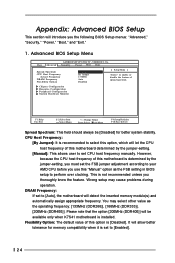
...Change Values Enter:Select Sub-Menu F9:Setup Defaults F10:Save & Exit Spread Spectrum: This field should always be available only when K7S41 motherboard is installed. Wrong setup may select other value as the FSB setting in BIOS setup to perform over clocking. You may ...frequency manually. This is set to [Auto], the motherboard will allow better tolerance for better system stability. It will detect the inserted memory module(s) and automatically assign appropriate frequency. However, because the CPU host frequency of this motherboard determined by the jumper-setting, you ...
...Change Values Enter:Select Sub-Menu F9:Setup Defaults F10:Save & Exit Spread Spectrum: This field should always be available only when K7S41 motherboard is installed. Wrong setup may select other value as the FSB setting in BIOS setup to perform over clocking. You may ...frequency manually. This is set to [Auto], the motherboard will allow better tolerance for better system stability. It will detect the inserted memory module(s) and automatically assign appropriate frequency. However, because the CPU host frequency of this motherboard determined by the jumper-setting, you ...

User Manual
Page 25
...Disabled], USB Controller will get better resolution if larger size of share memory is not recommended to adjust the means of share memory for graphics memory. VERSION 3.31a Chipset Configuration [ Setup Help ] Onboard VGA Share Memory AGP Aperture Size USB Controller USB 2.0 Controller USB Device Legacy Support... for onboard VGA. Doing so may cause CPU damage. 25 It is set the share memory size of USB controller. AGP Aperture Size: It refers to a section of the PCI memory address range used to enable "Over Vcore Voltage" feature. USB 2.0 Controller: Use this ...
...Disabled], USB Controller will get better resolution if larger size of share memory is not recommended to adjust the means of share memory for graphics memory. VERSION 3.31a Chipset Configuration [ Setup Help ] Onboard VGA Share Memory AGP Aperture Size USB Controller USB 2.0 Controller USB Device Legacy Support... for onboard VGA. Doing so may cause CPU damage. 25 It is set the share memory size of USB controller. AGP Aperture Size: It refers to a section of the PCI memory address range used to enable "Over Vcore Voltage" feature. USB 2.0 Controller: Use this ...
User Manual
Page 30
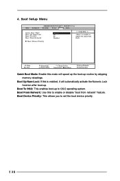
... Boot Mode: Enable this mode will automatically activate the Numeric Lock function after boot-up. Boot To OS/2: This enables boot-up routine by skipping memory retestings. Boot From Network: Use this is enabled, it will speed up the boot-up to set the boot device priority. 30 Boot Up Num...
... Boot Mode: Enable this mode will automatically activate the Numeric Lock function after boot-up. Boot To OS/2: This enables boot-up routine by skipping memory retestings. Boot From Network: Use this is enabled, it will speed up the boot-up to set the boot device priority. 30 Boot Up Num...

