
User Manual
Page 4
...1.2 Specifications 2 1.3 Motherboard Layout 5 1.4 I/O Panel 7 Chapter 2 Installation 9 2.1 Installation of Memory Modules (SO-DIMM) 10 2.2 Expansion Slot (PCI Express Slot) 12 2.3 Jumpers Setup 13 2.4 Onboard Headers and Connectors 14 2.5 M.2 WiFi/BT Module Installation Guide 17 Chapter 3 Software and Utilities Operation 19 3.1 Installing Drivers 19 3.2 ASRock Live Update & APP Shop 20 3.2.1 UI Overview 20 3.2.2 Apps 21 3.2.3 BIOS & Drivers 24 3.2.4 Setting 25 Chapter 4 UEFI SETUP UTILITY 26 4.1 Introduction 26 4.1.1 UEFI Menu Bar 26 4.1.2 Navigation Keys...
...1.2 Specifications 2 1.3 Motherboard Layout 5 1.4 I/O Panel 7 Chapter 2 Installation 9 2.1 Installation of Memory Modules (SO-DIMM) 10 2.2 Expansion Slot (PCI Express Slot) 12 2.3 Jumpers Setup 13 2.4 Onboard Headers and Connectors 14 2.5 M.2 WiFi/BT Module Installation Guide 17 Chapter 3 Software and Utilities Operation 19 3.1 Installing Drivers 19 3.2 ASRock Live Update & APP Shop 20 3.2.1 UI Overview 20 3.2.2 Apps 21 3.2.3 BIOS & Drivers 24 3.2.4 Setting 25 Chapter 4 UEFI SETUP UTILITY 26 4.1 Introduction 26 4.1.1 UEFI Menu Bar 26 4.1.2 Navigation Keys...
User Manual
Page 6
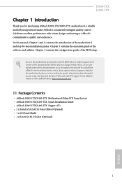
... (Mini-ITX Form Factor) • ASRock J5005-ITX/J4105-ITX Quick Installation Guide • ASRock J5005-ITX/J4105-ITX Support CD • 2 x Serial ATA (SATA) Data Cables (Optional) • 1 x I/O Panel Shield • 1 x Screw for purchasing ASRock J5005-ITX/J4105-ITX motherboard, a reliable motherboard produced under ASRock's consistently stringent quality control. J5005-ITX J4105-ITX Chapter 1 Introduction Thank you are using. Chapter 4 contains the configuration guide of the motherboard and step-by-step installation guides. You may find the latest VGA cards and CPU support list on...
... (Mini-ITX Form Factor) • ASRock J5005-ITX/J4105-ITX Quick Installation Guide • ASRock J5005-ITX/J4105-ITX Support CD • 2 x Serial ATA (SATA) Data Cables (Optional) • 1 x I/O Panel Shield • 1 x Screw for purchasing ASRock J5005-ITX/J4105-ITX motherboard, a reliable motherboard produced under ASRock's consistently stringent quality control. J5005-ITX J4105-ITX Chapter 1 Introduction Thank you are using. Chapter 4 contains the configuration guide of the motherboard and step-by-step installation guides. You may find the latest VGA cards and CPU support list on...
User Manual
Page 7
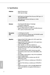
1.2 Specifications Platform • Mini-ITX Form Factor • Solid Capacitor design CPU • Intel® Quad-Core Pentium® Silver Processor J5005 (up to 2.8 GHz) (for J5005-ITX) • Intel® Quad-Core Processor J4105 (up to 750MHz) (for J4105-ITX) Memory • Dual Channel DDR4 Memory Technology • 2 x DDR4 SO-DIMM Slots * 2GB DRAM per module is required) 2 English capacity of system memory: 8GB Expansion Slot • 1 x PCI Express 2.0 x1 Slot • 1 x M.2 Socket (Key E), supports type 2230...
1.2 Specifications Platform • Mini-ITX Form Factor • Solid Capacitor design CPU • Intel® Quad-Core Pentium® Silver Processor J5005 (up to 2.8 GHz) (for J5005-ITX) • Intel® Quad-Core Processor J4105 (up to 750MHz) (for J4105-ITX) Memory • Dual Channel DDR4 Memory Technology • 2 x DDR4 SO-DIMM Slots * 2GB DRAM per module is required) 2 English capacity of system memory: 8GB Expansion Slot • 1 x PCI Express 2.0 x1 Slot • 1 x M.2 Socket (Key E), supports type 2230...
User Manual
Page 8
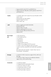
...) • 2 x USB 3.1 Gen1 Ports (Supports ESD Protection) • 1 x RJ-45 LAN Port with LED (ACT/LINK LED and SPEED LED) • HD Audio Jacks: Rear Speaker / Central / Bass / Line in / Front Speaker / Microphone Storage • 2 x SATA3 6.0 Gb/s Connectors, support NCQ, AHCI and Hot Plug • 2 x SATA3 6.0 Gb/s Connectors by ASMedia ASM1061, support NCQ, AHCI and Hot Plug Connector • 1 x COM Port Header • 1 x Chassis Intrusion and Speaker Header • 1 x CPU Fan Connector (3-pin) • 1 x Chassis Fan Connector (3-pin) • 1 x 24 pin ATX Power Connector •...
...) • 2 x USB 3.1 Gen1 Ports (Supports ESD Protection) • 1 x RJ-45 LAN Port with LED (ACT/LINK LED and SPEED LED) • HD Audio Jacks: Rear Speaker / Central / Bass / Line in / Front Speaker / Microphone Storage • 2 x SATA3 6.0 Gb/s Connectors, support NCQ, AHCI and Hot Plug • 2 x SATA3 6.0 Gb/s Connectors by ASMedia ASM1061, support NCQ, AHCI and Hot Plug Connector • 1 x COM Port Header • 1 x Chassis Intrusion and Speaker Header • 1 x CPU Fan Connector (3-pin) • 1 x Chassis Fan Connector (3-pin) • 1 x 24 pin ATX Power Connector •...

User Manual
Page 9
... GUI support • Supports Plug and Play • ACPI 5.0 compliant wake up events • Supports jumperfree • SMBIOS 3.0 support Hardware Monitor • CPU/Chassis temperature sensing • CPU/Chassis Fan Tachometer • CPU/Chassis Quiet Fan (Auto adjust chassis fan speed by CPU temperature) • CPU/Chassis Fan multi-speed control • CASE OPEN detection • Voltage monitoring: +12V, +5V, +3.3V, CPU Vcore OS • Microsoft® Windows® 10 64-bit Certifications • FCC, CE • ErP/EuP ready (ErP/EuP ready power supply is...
... GUI support • Supports Plug and Play • ACPI 5.0 compliant wake up events • Supports jumperfree • SMBIOS 3.0 support Hardware Monitor • CPU/Chassis temperature sensing • CPU/Chassis Fan Tachometer • CPU/Chassis Quiet Fan (Auto adjust chassis fan speed by CPU temperature) • CPU/Chassis Fan multi-speed control • CASE OPEN detection • Voltage monitoring: +12V, +5V, +3.3V, CPU Vcore OS • Microsoft® Windows® 10 64-bit Certifications • FCC, CE • ErP/EuP ready (ErP/EuP ready power supply is...

User Manual
Page 11
Description 1 CPU Fan Connector (CPU_FAN1) 2 ATX Power Connector (ATXPWR1) 3 System Panel Header (PANEL1) 4 2 x 260-pin DDR4 SO-DIMM Slots (DDR4_A1, DDR4_B1) 5 Chassis Intrusion and Speaker Header (SPK_CI1) 6 Clear CMOS Jumper (CLRMOS1) 7 Chassis Fan Connector (CHA_FAN1) 8 COM Port Header (COM1) 9 USB 2.0 Header (USB_0_1) 10 USB 3.1 Gen1 Header (USB3_0_1) 11 USB 2.0 Header (USB_2) 12 SATA3 Connector (SATA3_1) 13 SATA3 Connector (SATA3_2) 14 SATA3 Connector (SATA3_A2) 15 SATA3 Connector (SATA3_A1) 16 Front Panel Audio Header (HD_AUDIO1) 6 English No.
Description 1 CPU Fan Connector (CPU_FAN1) 2 ATX Power Connector (ATXPWR1) 3 System Panel Header (PANEL1) 4 2 x 260-pin DDR4 SO-DIMM Slots (DDR4_A1, DDR4_B1) 5 Chassis Intrusion and Speaker Header (SPK_CI1) 6 Clear CMOS Jumper (CLRMOS1) 7 Chassis Fan Connector (CHA_FAN1) 8 COM Port Header (COM1) 9 USB 2.0 Header (USB_0_1) 10 USB 3.1 Gen1 Header (USB3_0_1) 11 USB 2.0 Header (USB_2) 12 SATA3 Connector (SATA3_1) 13 SATA3 Connector (SATA3_2) 14 SATA3 Connector (SATA3_A2) 15 SATA3 Connector (SATA3_A1) 16 Front Panel Audio Header (HD_AUDIO1) 6 English No.
User Manual
Page 14
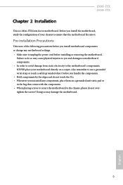
... following precautions before you install the motherboard, study the configuration of your motherboard directly on a grounded anti-static pad or in the bag that the motherboard fits into it. Before you install motherboard components or change any components, place them on a carpet. J5005-ITX J4105-ITX Chapter 2 Installation This is a Mini-ITX form factor motherboard. Failure to the motherboard's components, NEVER place your chassis to ensure that...
... following precautions before you install the motherboard, study the configuration of your motherboard directly on a grounded anti-static pad or in the bag that the motherboard fits into it. Before you install motherboard components or change any components, place them on a carpet. J5005-ITX J4105-ITX Chapter 2 Installation This is a Mini-ITX form factor motherboard. Failure to the motherboard's components, NEVER place your chassis to ensure that...

User Manual
Page 17
... "boot from Onboard VGA" as default even the user install a VGA card on the motherboard. Warning: To ensure better graphics compability, the BIOS is 1 PCI Express slot on PCIe slot. 12 English Before installing an expansion card, please make necessary hardware settings for PCI Express x1 lane width cards. Please read the documentation of the expansion card and make sure that the power supply is switched off or the power cord is used for the card before you start the installation. PCIe slot...
... "boot from Onboard VGA" as default even the user install a VGA card on the motherboard. Warning: To ensure better graphics compability, the BIOS is 1 PCI Express slot on PCIe slot. 12 English Before installing an expansion card, please make necessary hardware settings for PCI Express x1 lane width cards. Please read the documentation of the expansion card and make sure that the power supply is switched off or the power cord is used for the card before you start the installation. PCIe slot...
User Manual
Page 18
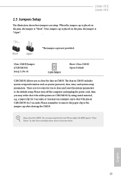
... and unplug the power cord, then you may use a jumper cap to short the pin on CLRCMOS1 by using metal material, e.g., a paper clip for 3 seconds; Please adjust the BIOS option "Clear Status" to remove the paper clip or the jumper cap after clearing the CMOS. Please remember to clear the record of previous chassis intrusion status. The data in CMOS. English 13 J5005-ITX J4105-ITX 2.3 Jumpers Setup The illustration shows...
... and unplug the power cord, then you may use a jumper cap to short the pin on CLRCMOS1 by using metal material, e.g., a paper clip for 3 seconds; Please adjust the BIOS option "Clear Status" to remove the paper clip or the jumper cap after clearing the CMOS. Please remember to clear the record of previous chassis intrusion status. The data in CMOS. English 13 J5005-ITX J4105-ITX 2.3 Jumpers Setup The illustration shows...

User Manual
Page 19
... NOT jumpers. A front panel module mainly consists of power button, reset button, power LED, hard drive activity LED, speaker and etc. You may differ by chassis. RESET (Reset Button): Connect to this header according to perform a normal restart. The LED keeps blinking when the system is operating. System Panel Header (9-pin PANEL1) (see p.5, No. 5) SPEAKER DUMMY DUMMY +5V DUMMY GND SIGNAL 1 Please connect the chassis intrusion and the chassis speaker to the reset button on the chassis front panel. 2.4 Onboard Headers and Connectors Onboard headers and connectors are...
... NOT jumpers. A front panel module mainly consists of power button, reset button, power LED, hard drive activity LED, speaker and etc. You may differ by chassis. RESET (Reset Button): Connect to this header according to perform a normal restart. The LED keeps blinking when the system is operating. System Panel Header (9-pin PANEL1) (see p.5, No. 5) SPEAKER DUMMY DUMMY +5V DUMMY GND SIGNAL 1 Please connect the chassis intrusion and the chassis speaker to the reset button on the chassis front panel. 2.4 Onboard Headers and Connectors Onboard headers and connectors are...
User Manual
Page 20
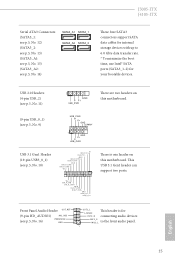
This USB 3.1 Gen1 header can support two ports. J5005-ITX J4105-ITX Serial ATA3 Connectors (SATA3_1: see p.5, No. 12) (SATA3_2: see p.5, No. 13) (SATA3_A1: see p.5, No. 15) (SATA3_A2: see p.5, No. 14) SATA3_A1 SATA3_1 SATA3_A2 SATA3_2 These four SATA3 connectors support SATA data cables for your bootable devices. P+ USB_PWR There are two headers on this motherboard. (9-pin USB_0_1) (see p.5, No. 9) USB_PWR PP+ GND DUMMY 1 GND P+ PUSB_PWR USB 3.1 Gen1 Header (19-pin USB3_0_1...
This USB 3.1 Gen1 header can support two ports. J5005-ITX J4105-ITX Serial ATA3 Connectors (SATA3_1: see p.5, No. 12) (SATA3_2: see p.5, No. 13) (SATA3_A1: see p.5, No. 15) (SATA3_A2: see p.5, No. 14) SATA3_A1 SATA3_1 SATA3_A2 SATA3_2 These four SATA3 connectors support SATA data cables for your bootable devices. P+ USB_PWR There are two headers on this motherboard. (9-pin USB_0_1) (see p.5, No. 9) USB_PWR PP+ GND DUMMY 1 GND P+ PUSB_PWR USB 3.1 Gen1 Header (19-pin USB3_0_1...

User Manual
Page 21
... pin. ATX Power Connector (24-pin ATXPWR1) (see p.5, No. 4) 12 24 1 13 Serial Port Header (9-pin COM1) (see p.5, No. 7) GND FAN_VOLTAGE CHA_FAN_SPEED Please connect fan cable to the fan connector and match the black wire to the front panel audio header by the steps below: A. If you use a 20-pin ATX power supply, please plug it to the ground pin. D. Chassis Fan Connector (3-pin CHA_FAN1) (see p.5, No. 8) RRXD1 DDTR#1 DDSR#1 CCTS#1 1 RRI#1 RRTS#1 GND TTXD1 DDCD#1 This motherboard provides a 24-pin ATX power connector...
... pin. ATX Power Connector (24-pin ATXPWR1) (see p.5, No. 4) 12 24 1 13 Serial Port Header (9-pin COM1) (see p.5, No. 7) GND FAN_VOLTAGE CHA_FAN_SPEED Please connect fan cable to the fan connector and match the black wire to the front panel audio header by the steps below: A. If you use a 20-pin ATX power supply, please plug it to the ground pin. D. Chassis Fan Connector (3-pin CHA_FAN1) (see p.5, No. 8) RRXD1 DDTR#1 DDSR#1 CCTS#1 1 RRI#1 RRTS#1 GND TTXD1 DDCD#1 This motherboard provides a 24-pin ATX power connector...
User Manual
Page 22
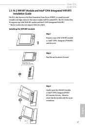
... A 20o 17 The M.2 Socket (Key E) supports type 2230 WiFi/BT module and Intel® CNVi (Integrated WiFi/BT). * The M.2 socket does not support SATA M.2 SSDs. Please be used. J5005-ITX J4105-ITX 2.5 M.2 WiFi/BT Module and Intel® CNVi (Integrated WiFi/BT) Installation Guide The M.2, also known as the Next Generation Form Factor (NGFF), is a small size and versatile card edge connector that the module only...
... A 20o 17 The M.2 Socket (Key E) supports type 2230 WiFi/BT module and Intel® CNVi (Integrated WiFi/BT). * The M.2 socket does not support SATA M.2 SSDs. Please be used. J5005-ITX J4105-ITX 2.5 M.2 WiFi/BT Module and Intel® CNVi (Integrated WiFi/BT) Installation Guide The M.2, also known as the Next Generation Form Factor (NGFF), is a small size and versatile card edge connector that the module only...
User Manual
Page 24
... useful utilities that the motherboard supports. Utilities Menu The Utilities Menu shows the application software that enhance the motherboard's features. The CD automatically displays the Main Menu if "AUTORUN" is enabled in the Support CD to install those required drivers. Please click Install All or follow the installation wizard to your system will be auto-detected and listed on the file "ASRSETUP.EXE" in your CD-ROM drive. If the Main Menu does not appear automatically, locate...
... useful utilities that the motherboard supports. Utilities Menu The Utilities Menu shows the application software that enhance the motherboard's features. The CD automatically displays the Main Menu if "AUTORUN" is enabled in the Support CD to install those required drivers. Please click Install All or follow the installation wizard to your system will be auto-detected and listed on the file "ASRSETUP.EXE" in your CD-ROM drive. If the Main Menu does not appear automatically, locate...

User Manual
Page 31
... not exactly match what you see on the system chassis. Because the UEFI software is constantly being updated, the following selections: Main For setting system time/date information Advanced For advanced system configurations Tool Useful tools H/W Monitor Displays current hardware status Security For security settings Boot For configuring boot settings and boot priority Exit Exit the current screen or the UEFI Setup Utility English 26 You may also restart by...
... not exactly match what you see on the system chassis. Because the UEFI software is constantly being updated, the following selections: Main For setting system time/date information Advanced For advanced system configurations Tool Useful tools H/W Monitor Displays current hardware status Security For security settings Boot For configuring boot settings and boot priority Exit Exit the current screen or the UEFI Setup Utility English 26 You may also restart by...
User Manual
Page 36
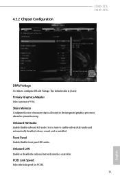
...primary VGA. Share Memory Configure the size of memory that is [Auto]. The default value is allocated to the integrated graphics processor when the system boots up. Onboard HD Audio Enable/disable onboard HD audio. PCIE1 Link Speed Select the link speed for PCIE1. 31 English Front Panel Enable/disable front panel HD audio. 4.3.2 Chipset Configuration J5005-ITX J4105-ITX DRAM Voltage Use this to enable onboard HD audio and automatically disable it when a sound card is installed. Set to Auto to configure DRAM Voltage. Onboard LAN Enable or disable the onboard network interface...
...primary VGA. Share Memory Configure the size of memory that is [Auto]. The default value is allocated to the integrated graphics processor when the system boots up. Onboard HD Audio Enable/disable onboard HD audio. PCIE1 Link Speed Select the link speed for PCIE1. 31 English Front Panel Enable/disable front panel HD audio. 4.3.2 Chipset Configuration J5005-ITX J4105-ITX DRAM Voltage Use this to enable onboard HD audio and automatically disable it when a sound card is installed. Set to Auto to configure DRAM Voltage. Onboard LAN Enable or disable the onboard network interface...
User Manual
Page 44
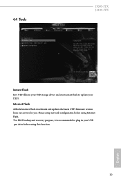
4.4 Tools J5005-ITX J4105-ITX Instant Flash Save UEFI files in your UEFI. Please setup network configuration before using Internet Flash. *For BIOS backup and recovery purpose, it is recommended to plug in your USB storage device and run Instant Flash to update your USB pen drive before using this function. 39 English Internet Flash ASRock Internet Flash downloads and updates the latest UEFI firmware version from our servers for you.
4.4 Tools J5005-ITX J4105-ITX Instant Flash Save UEFI files in your UEFI. Please setup network configuration before using Internet Flash. *For BIOS backup and recovery purpose, it is recommended to plug in your USB storage device and run Instant Flash to update your USB pen drive before using this function. 39 English Internet Flash ASRock Internet Flash downloads and updates the latest UEFI firmware version from our servers for you.

User Manual
Page 45
UEFI Download Server Select a server to configure internet connection settings for Internet Flash. Internet Setting Enable or disable sound effects in the setup utility. Network Configuration Use this to download the UEFI firmware. 40 English
UEFI Download Server Select a server to configure internet connection settings for Internet Flash. Internet Setting Enable or disable sound effects in the setup utility. Network Configuration Use this to download the UEFI firmware. 40 English
User Manual
Page 46
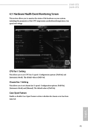
... [Automatic Mode]. The default value is [Full On]. Chassis Fan 1 Setting This allows you to monitor the status of the hardware on your system, including the parameters of the CPU temperature, motherboard temperature, fan speed and voltage. Configuration options: [Full On], [Automatic Mode] and [Manual]. Case Open Feature Enable or disable Case Open Feature to set chassis fan 1's speed. J5005-ITX J4105-ITX 4.5 Hardware Health Event Monitoring Screen This section allows you to set CPU fan 1's speed. The default value is [Full On]. CPU Fan 1 Setting This allows...
... [Automatic Mode]. The default value is [Full On]. Chassis Fan 1 Setting This allows you to monitor the status of the hardware on your system, including the parameters of the CPU temperature, motherboard temperature, fan speed and voltage. Configuration options: [Full On], [Automatic Mode] and [Manual]. Case Open Feature Enable or disable Case Open Feature to set chassis fan 1's speed. J5005-ITX J4105-ITX 4.5 Hardware Health Event Monitoring Screen This section allows you to set CPU fan 1's speed. The default value is [Full On]. CPU Fan 1 Setting This allows...

User Manual
Page 47
Supervisor Password Set or change the password for the user account. Leave it blank and press enter to remove the password. Users are unable to change the supervisor/user password for the system. Intel(R) Platform Trust Technology Enable/disable Intel PTT in the UEFI Setup Utility. 4.6 Security Screen In this option to use discrete TPM Module. 42 English You may set or change the settings in ME. User Password Set or change the settings in the UEFI Setup Utility. Secure Boot Enable to change the password for...
Supervisor Password Set or change the password for the user account. Leave it blank and press enter to remove the password. Users are unable to change the supervisor/user password for the system. Intel(R) Platform Trust Technology Enable/disable Intel PTT in the UEFI Setup Utility. 4.6 Security Screen In this option to use discrete TPM Module. 42 English You may set or change the settings in ME. User Password Set or change the settings in the UEFI Setup Utility. Secure Boot Enable to change the password for...


