User Manual
Page 4
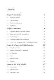
... Headers and Connectors 14 2.5 Intel® CNVi (Integrated WiFi/BT) Installation Guide 18 Chapter 3 Software and Utilities Operation 20 3.1 Installing Drivers 20 3.2 ASRock Live Update & APP Shop 21 3.2.1 UI Overview 21 3.2.2 Apps 22 3.2.3 BIOS & Drivers 25 3.2.4 Setting 26 Chapter 4 UEFI SETUP UTILITY 27 4.1 Introduction 27 4.1.1 UEFI Menu Bar 27 4.1.2 Navigation Keys 28
... Headers and Connectors 14 2.5 Intel® CNVi (Integrated WiFi/BT) Installation Guide 18 Chapter 3 Software and Utilities Operation 20 3.1 Installing Drivers 20 3.2 ASRock Live Update & APP Shop 21 3.2.1 UI Overview 21 3.2.2 Apps 22 3.2.3 BIOS & Drivers 25 3.2.4 Setting 26 Chapter 4 UEFI SETUP UTILITY 27 4.1 Introduction 27 4.1.1 UEFI Menu Bar 27 4.1.2 Navigation Keys 28
User Manual
Page 6
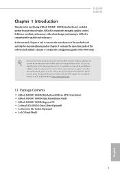
... of the BIOS setup. J4105M J4005M Chapter 1 Introduction Thank you are using. It delivers excellent performance with robust design conforming to ASRock's commitment to this documentation occur, the updated version will be available on ASRock's website as well. ASRock website http://www.asrock.com. 1.1 Package Contents • ASRock J4105M / J4005M Motherboard (Micro ATX Form Factor) • ASRock J4105M / J4005M Quick...
... of the BIOS setup. J4105M J4005M Chapter 1 Introduction Thank you are using. It delivers excellent performance with robust design conforming to ASRock's commitment to this documentation occur, the updated version will be available on ASRock's website as well. ASRock website http://www.asrock.com. 1.1 Package Contents • ASRock J4105M / J4005M Motherboard (Micro ATX Form Factor) • ASRock J4105M / J4005M Quick...

User Manual
Page 9
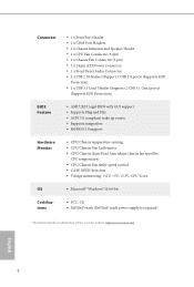
... Audio Connector • 3 x USB 2.0 Headers (Support 5 USB 2.0 ports) (Supports ESD Protection) • 1 x USB 3.1 Gen1 Header (Supports 2 USB 3.1 Gen1 ports) (Supports ESD Protection) BIOS Feature • AMI UEFI Legal BIOS with GUI support • Supports Plug and Play • ACPI 5.0 compliant wake up events • Supports jumperfree • SMBIOS 3.0 support Hardware Monitor •... Certifications • FCC, CE • ErP/EuP ready (ErP/EuP ready power supply is required) * For detailed product information, please visit our website: http://www.asrock.com English 4
... Audio Connector • 3 x USB 2.0 Headers (Support 5 USB 2.0 ports) (Supports ESD Protection) • 1 x USB 3.1 Gen1 Header (Supports 2 USB 3.1 Gen1 ports) (Supports ESD Protection) BIOS Feature • AMI UEFI Legal BIOS with GUI support • Supports Plug and Play • ACPI 5.0 compliant wake up events • Supports jumperfree • SMBIOS 3.0 support Hardware Monitor •... Certifications • FCC, CE • ErP/EuP ready (ErP/EuP ready power supply is required) * For detailed product information, please visit our website: http://www.asrock.com English 4

User Manual
Page 10
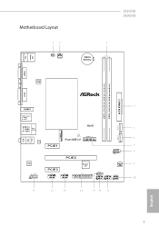
1.3 Motherboard Layout 12 1 CLRMOS1 CPU_FAN1 J4105M J4005M 3 CMOS Battery PS2 Mouse PS2 Keyboard VGA1 BIOS ROM AT X P W R 1 DDR4_A1 (64 bit, 288-pin module) DDR4_A2 (64 bit, 288-pin module) DVI1 4 HDMI1 USB 3.1 Gen1 T: USB0 B: USB1 Top: LINE IN Center: FRONT Bottom: MIC IN USB 2.0 T: USB0 Top: RJ-45 B: USB1 RoHS 5 SATA3_1 SATA3_2 CNVI1 CNVI1_CT1 USB3_1_2 Front USB 3.0 LAN PCIE1 PCIE2 6 7 PLED PWRBTN 1 HDLED RESET PANEL1 AUDIO CODEC Super 9 I/O PCIE3 HD_AUDIO1 COM2 1 COM1 1 LPT1 USB_6 1 1 USB_2_3 USB_4_5 SPK_CI1 1 1 1 1 13 12 English 5
1.3 Motherboard Layout 12 1 CLRMOS1 CPU_FAN1 J4105M J4005M 3 CMOS Battery PS2 Mouse PS2 Keyboard VGA1 BIOS ROM AT X P W R 1 DDR4_A1 (64 bit, 288-pin module) DDR4_A2 (64 bit, 288-pin module) DVI1 4 HDMI1 USB 3.1 Gen1 T: USB0 B: USB1 Top: LINE IN Center: FRONT Bottom: MIC IN USB 2.0 T: USB0 Top: RJ-45 B: USB1 RoHS 5 SATA3_1 SATA3_2 CNVI1 CNVI1_CT1 USB3_1_2 Front USB 3.0 LAN PCIE1 PCIE2 6 7 PLED PWRBTN 1 HDLED RESET PANEL1 AUDIO CODEC Super 9 I/O PCIE3 HD_AUDIO1 COM2 1 COM1 1 LPT1 USB_6 1 1 USB_2_3 USB_4_5 SPK_CI1 1 1 1 1 13 12 English 5
User Manual
Page 17
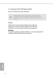
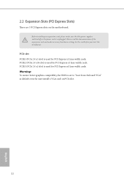
... lane width cards. PCIe slot: PCIE1 (PCIe 2.0 x1 slot) is used for PCI Express x1 lane width cards. Warning: To ensure better graphics compability, the BIOS is unplugged. Please read the documentation of the expansion card and make sure that the power supply is switched off or the power cord is...
... lane width cards. PCIe slot: PCIE1 (PCIe 2.0 x1 slot) is used for PCI Express x1 lane width cards. Warning: To ensure better graphics compability, the BIOS is unplugged. Please read the documentation of the expansion card and make sure that the power supply is switched off or the power cord is...
User Manual
Page 18
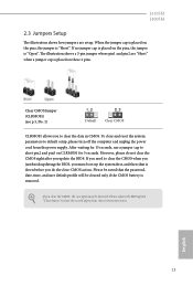
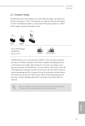
...2 pins. Clear CMOS Jumper (CLRMOS1) (see p.5, No. 1) Default Clear CMOS CLRMOS1 allows you to clear the CMOS when you just finish updating the BIOS, you must boot up the system first, and then shut it down before you do not clear the CMOS right after you need to clear... BIOS option "Clear Status" to default setup, please turn off the computer and unplug the power cord from the power supply. However, please do the clear-CMOS action. To clear and reset the system parameters to clear the record of previous chassis intrusion status. After waiting for 5 seconds. J4105M ...
...2 pins. Clear CMOS Jumper (CLRMOS1) (see p.5, No. 1) Default Clear CMOS CLRMOS1 allows you to clear the CMOS when you just finish updating the BIOS, you must boot up the system first, and then shut it down before you do not clear the CMOS right after you need to clear... BIOS option "Clear Status" to default setup, please turn off the computer and unplug the power cord from the power supply. However, please do the clear-CMOS action. To clear and reset the system parameters to clear the record of previous chassis intrusion status. After waiting for 5 seconds. J4105M ...
User Manual
Page 30
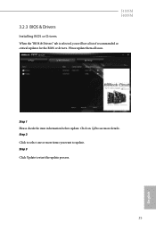
Please update them all soon. Step 3 Click Update to see a list of recommended or critical updates for the BIOS or drivers. Click to select one or more items you will see more details. Step 1 Please check the item information before update. J4105M J4005M 3.2.3 BIOS & Drivers Installing BIOS or Drivers When the "BIOS & Drivers" tab is selected, you want to update. Click on Step 2 to start the update process. 25 English
Please update them all soon. Step 3 Click Update to see a list of recommended or critical updates for the BIOS or drivers. Click to select one or more items you will see more details. Step 1 Please check the item information before update. J4105M J4005M 3.2.3 BIOS & Drivers Installing BIOS or Drivers When the "BIOS & Drivers" tab is selected, you want to update. Click on Step 2 to start the update process. 25 English
User Manual
Page 44
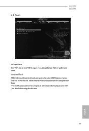
4.4 Tools J4105M J4005M Instant Flash Save UEFI files in your UEFI. Please setup network configuration before using Internet Flash. *For BIOS backup and recovery purpose, it is recommended to plug in your USB storage device and run Instant Flash to update your USB pen drive before using this function. 39 English Internet Flash ASRock Internet Flash downloads and updates the latest UEFI firmware version from our servers for you.
4.4 Tools J4105M J4005M Instant Flash Save UEFI files in your UEFI. Please setup network configuration before using Internet Flash. *For BIOS backup and recovery purpose, it is recommended to plug in your USB storage device and run Instant Flash to update your USB pen drive before using this function. 39 English Internet Flash ASRock Internet Flash downloads and updates the latest UEFI firmware version from our servers for you.
Quick Installation Guide
Page 3
Motherboard Layout 12 1 CLRMOS1 CPU_FAN1 PS2 Mouse PS2 Keyboard VGA1 BIOS ROM J4105M J4005M 3 CMOS Battery AT X P W R 1 DDR4_A1 (64 bit, 288-pin module) DDR4_A2 (64 bit, 288-pin module) DVI1 4 HDMI1 USB 3.1 Gen1 T: USB0 B: USB1 Top: LINE IN Center: FRONT Bottom: MIC IN USB 2.0 T: USB0 Top: RJ-45 B: USB1 RoHS 5 SATA3_1 SATA3_2 CNVI1 CNVI1_CT1 USB3_1_2 Front USB 3.0 LAN PCIE1 PCIE2 6 7 PLED PWRBTN 1 HDLED RESET PANEL1 AUDIO CODEC Super 9 I/O PCIE3 HD_AUDIO1 COM2 1 COM1 1 LPT1 USB_6 1 1 USB_2_3 USB_4_5 SPK_CI1 1 1 1 1 13 12 English 1
Motherboard Layout 12 1 CLRMOS1 CPU_FAN1 PS2 Mouse PS2 Keyboard VGA1 BIOS ROM J4105M J4005M 3 CMOS Battery AT X P W R 1 DDR4_A1 (64 bit, 288-pin module) DDR4_A2 (64 bit, 288-pin module) DVI1 4 HDMI1 USB 3.1 Gen1 T: USB0 B: USB1 Top: LINE IN Center: FRONT Bottom: MIC IN USB 2.0 T: USB0 Top: RJ-45 B: USB1 RoHS 5 SATA3_1 SATA3_2 CNVI1 CNVI1_CT1 USB3_1_2 Front USB 3.0 LAN PCIE1 PCIE2 6 7 PLED PWRBTN 1 HDLED RESET PANEL1 AUDIO CODEC Super 9 I/O PCIE3 HD_AUDIO1 COM2 1 COM1 1 LPT1 USB_6 1 1 USB_2_3 USB_4_5 SPK_CI1 1 1 1 1 13 12 English 1
Quick Installation Guide
Page 7
....asrock.com. 1.1 Package Contents • ASRock J4105M / J4005M Motherboard (Micro ATX Form Factor) • ASRock J4105M / J4005M Quick Installation Guide • ASRock J4105M / J4005M Support CD • 2 x Serial ATA (SATA) Data Cables (Optional) • 1 x Screw for purchasing ASRock J4105M / J4005M motherboard, a reliable motherboard produced under ASRock's consistently stringent quality control. If you are using. Because the motherboard specifications and the BIOS...
....asrock.com. 1.1 Package Contents • ASRock J4105M / J4005M Motherboard (Micro ATX Form Factor) • ASRock J4105M / J4005M Quick Installation Guide • ASRock J4105M / J4005M Support CD • 2 x Serial ATA (SATA) Data Cables (Optional) • 1 x Screw for purchasing ASRock J4105M / J4005M motherboard, a reliable motherboard produced under ASRock's consistently stringent quality control. If you are using. Because the motherboard specifications and the BIOS...
Quick Installation Guide
Page 10
Connector BIOS Feature Hardware Monitor OS Certifications • 1 x Print Port Header • 2 x COM Port Headers • 1 x Chassis Intrusion and Speaker...2.0 ports) (Supports ESD Protection) • 1 x USB 3.1 Gen1 Header (Supports 2 USB 3.1 Gen1 ports) (Supports ESD Protection) • AMI UEFI Legal BIOS with GUI support • Supports Plug and Play • ACPI 5.0 compliant wake up events • Supports jumperfree • SMBIOS 3.0 support • CPU/Chassis...power supply is required) * For detailed product information, please visit our website: http://www.asrock.com English 8
Connector BIOS Feature Hardware Monitor OS Certifications • 1 x Print Port Header • 2 x COM Port Headers • 1 x Chassis Intrusion and Speaker...2.0 ports) (Supports ESD Protection) • 1 x USB 3.1 Gen1 Header (Supports 2 USB 3.1 Gen1 ports) (Supports ESD Protection) • AMI UEFI Legal BIOS with GUI support • Supports Plug and Play • ACPI 5.0 compliant wake up events • Supports jumperfree • SMBIOS 3.0 support • CPU/Chassis...power supply is required) * For detailed product information, please visit our website: http://www.asrock.com English 8
Quick Installation Guide
Page 14
Warning: To ensure better graphics compability, the BIOS is set to "boot from Onboard VGA" as default even the user install a VGA card on the motherboard. PCIE2 (PCIe 2.0 x16 slot) is unplugged. Please ...
Warning: To ensure better graphics compability, the BIOS is set to "boot from Onboard VGA" as default even the user install a VGA card on the motherboard. PCIE2 (PCIe 2.0 x16 slot) is unplugged. Please ...
Quick Installation Guide
Page 15
...waiting for 15 seconds, use a jumper cap to clear the CMOS when you just finish updating the BIOS, you must boot up the system first, and then shut it down before you do not clear the CMOS... right after you update the BIOS. Please adjust the BIOS option "Clear Status" to default setup, please turn off the computer and unplug the power cord ... If no jumper cap is placed on the pins, the jumper is removed. J4105M J4005M 2.3 Jumpers Setup The illustration shows how jumpers are "Short" when a jumper cap is placed on these 2 pins....
...waiting for 15 seconds, use a jumper cap to clear the CMOS when you just finish updating the BIOS, you must boot up the system first, and then shut it down before you do not clear the CMOS... right after you update the BIOS. Please adjust the BIOS option "Clear Status" to default setup, please turn off the computer and unplug the power cord ... If no jumper cap is placed on the pins, the jumper is removed. J4105M J4005M 2.3 Jumpers Setup The illustration shows how jumpers are "Short" when a jumper cap is placed on these 2 pins....


