User Manual
Page 4
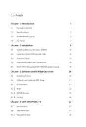
... Contents 1 1.2 Specifications 2 1.3 Motherboard Layout 5 1.4 I/O Panel 7 Chapter 2 Installation 9 2.1 Installing Memory Modules (DIMM) 10 2.2 Expansion Slots (PCI Express Slots) 12 2.3 Jumpers Setup 13 2.4 Onboard Headers and Connectors 14 2.5 Intel® CNVi (Integrated WiFi/BT) Installation Guide 18 Chapter 3 Software and Utilities Operation 20 3.1 Installing Drivers 20 3.2 ASRock Live Update & APP Shop 21 3.2.1 UI Overview 21 3.2.2 Apps 22 3.2.3 BIOS & Drivers 25 3.2.4 Setting 26 Chapter 4 UEFI SETUP UTILITY 27 4.1 Introduction 27 4.1.1 UEFI Menu Bar...
... Contents 1 1.2 Specifications 2 1.3 Motherboard Layout 5 1.4 I/O Panel 7 Chapter 2 Installation 9 2.1 Installing Memory Modules (DIMM) 10 2.2 Expansion Slots (PCI Express Slots) 12 2.3 Jumpers Setup 13 2.4 Onboard Headers and Connectors 14 2.5 Intel® CNVi (Integrated WiFi/BT) Installation Guide 18 Chapter 3 Software and Utilities Operation 20 3.1 Installing Drivers 20 3.2 ASRock Live Update & APP Shop 21 3.2.1 UI Overview 21 3.2.2 Apps 22 3.2.3 BIOS & Drivers 25 3.2.4 Setting 26 Chapter 4 UEFI SETUP UTILITY 27 4.1 Introduction 27 4.1.1 UEFI Menu Bar...
User Manual
Page 6
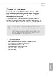
... the updated version will be available on ASRock's website as well. ASRock website http://www.asrock.com. 1.1 Package Contents • ASRock J4105M / J4005M Motherboard (Micro ATX Form Factor) • ASRock J4105M / J4005M Quick Installation Guide • ASRock J4105M / J4005M Support CD • 2 x Serial ATA (SATA) Data Cables (Optional) • 1 x Screw for purchasing ASRock J4105M / J4005M motherboard, a reliable motherboard produced under ASRock's consistently stringent quality control. Chapter 3 contains the operation guide of the BIOS setup. Chapter 4 contains the configuration...
... the updated version will be available on ASRock's website as well. ASRock website http://www.asrock.com. 1.1 Package Contents • ASRock J4105M / J4005M Motherboard (Micro ATX Form Factor) • ASRock J4105M / J4005M Quick Installation Guide • ASRock J4105M / J4005M Support CD • 2 x Serial ATA (SATA) Data Cables (Optional) • 1 x Screw for purchasing ASRock J4105M / J4005M motherboard, a reliable motherboard produced under ASRock's consistently stringent quality control. Chapter 3 contains the operation guide of the BIOS setup. Chapter 4 contains the configuration...
User Manual
Page 8
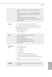
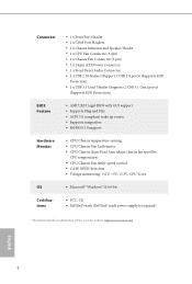
...; Supports Energy Efficient Ethernet 802.3az • Supports PXE Rear Panel I/O • 1 x PS/2 Mouse Port • 1 x PS/2 Keyboard Port • 1 x D-Sub Port • 1 x DVI-D Port • 1 x HDMI Port • 2 x USB 2.0 Ports (Supports ESD Protection) • 2 x USB 3.1 Gen1 Ports (Supports ESD Protection) • 1 x RJ-45 LAN Port with max. J4105M J4005M • Supports D-Sub with LED (ACT/LINK LED and SPEED LED) • HD Audio Jacks: Line in / Front Speaker / Microphone Storage • 2 x SATA3 6.0 Gb/s Connectors, support NCQ, AHCI and Hot Plug English...
...; Supports Energy Efficient Ethernet 802.3az • Supports PXE Rear Panel I/O • 1 x PS/2 Mouse Port • 1 x PS/2 Keyboard Port • 1 x D-Sub Port • 1 x DVI-D Port • 1 x HDMI Port • 2 x USB 2.0 Ports (Supports ESD Protection) • 2 x USB 3.1 Gen1 Ports (Supports ESD Protection) • 1 x RJ-45 LAN Port with max. J4105M J4005M • Supports D-Sub with LED (ACT/LINK LED and SPEED LED) • HD Audio Jacks: Line in / Front Speaker / Microphone Storage • 2 x SATA3 6.0 Gb/s Connectors, support NCQ, AHCI and Hot Plug English...

User Manual
Page 9
Connector • 1 x Print Port Header • 2 x COM Port Headers • 1 x Chassis Intrusion and Speaker Header • 1 x CPU Fan Connector (3-pin) • 1 x Chassis Fan Connector (3-pin) • 1 x 24 pin ATX Power Connector • 1 x Front Panel Audio Connector • 3 x USB 2.0 Headers (Support 5 USB 2.0 ports) (Supports ESD Protection) • 1 x USB 3.1 Gen1 Header (Supports 2 USB 3.1 Gen1 ports) (Supports ESD Protection) BIOS Feature • AMI UEFI Legal BIOS with GUI support • Supports Plug and Play • ACPI 5.0 compliant wake up events • Supports ...
Connector • 1 x Print Port Header • 2 x COM Port Headers • 1 x Chassis Intrusion and Speaker Header • 1 x CPU Fan Connector (3-pin) • 1 x Chassis Fan Connector (3-pin) • 1 x 24 pin ATX Power Connector • 1 x Front Panel Audio Connector • 3 x USB 2.0 Headers (Support 5 USB 2.0 ports) (Supports ESD Protection) • 1 x USB 3.1 Gen1 Header (Supports 2 USB 3.1 Gen1 ports) (Supports ESD Protection) BIOS Feature • AMI UEFI Legal BIOS with GUI support • Supports Plug and Play • ACPI 5.0 compliant wake up events • Supports ...
User Manual
Page 11
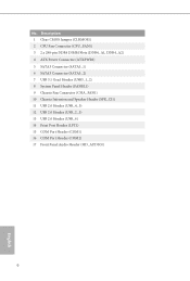
No. Description 1 Clear CMOS Jumper (CLRMOS1) 2 CPU Fan Connector (CPU_FAN1) 3 2 x 288-pin DDR4 DIMM Slots (DDR4_A1, DDR4_A2) 4 ATX Power Connector (ATXPWR1) 5 SATA3 Connector (SATA3_1) 6 SATA3 Connector (SATA3_2) 7 USB 3.1 Gen1 Header (USB3_1_2) 8 System Panel Header (PANEL1) 9 Chassis Fan Connector (CHA_FAN1) 10 Chassis Intrusion and Speaker Header (SPK_CI1) 11 USB 2.0 Header (USB_4_5) 12 USB 2.0 Header (USB_2_3) 13 USB 2.0 Header (USB_6) 14 Print Port Header (LPT1) 15 COM Port Header (COM1) 16 COM Port Header (COM2) 17 Front Panel Audio Header (HD_AUDIO1) 6 English
No. Description 1 Clear CMOS Jumper (CLRMOS1) 2 CPU Fan Connector (CPU_FAN1) 3 2 x 288-pin DDR4 DIMM Slots (DDR4_A1, DDR4_A2) 4 ATX Power Connector (ATXPWR1) 5 SATA3 Connector (SATA3_1) 6 SATA3 Connector (SATA3_2) 7 USB 3.1 Gen1 Header (USB3_1_2) 8 System Panel Header (PANEL1) 9 Chassis Fan Connector (CHA_FAN1) 10 Chassis Intrusion and Speaker Header (SPK_CI1) 11 USB 2.0 Header (USB_4_5) 12 USB 2.0 Header (USB_2_3) 13 USB 2.0 Header (USB_6) 14 Print Port Header (LPT1) 15 COM Port Header (COM1) 16 COM Port Header (COM2) 17 Front Panel Audio Header (HD_AUDIO1) 6 English
User Manual
Page 17
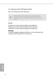
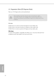
... better graphics compability, the BIOS is used for PCI Express x1 lane width cards. 2.2 Expansion Slots (PCI Express Slots) There are 3 PCI Express slots on PCIe slot. 12 English PCIe slot: PCIE1 (PCIe 2.0 x1 slot) is used for PCI Express x1 lane width cards. Before installing an expansion card, please make necessary hardware settings for PCI Express x1 lane width cards. PCIE3 (PCIe 2.0 x1 slot) is used for the card before you start the installation. PCIE2 (PCIe 2.0 x16 slot) is set to "boot from Onboard VGA" as default even the user install a VGA card on the motherboard...
... better graphics compability, the BIOS is used for PCI Express x1 lane width cards. 2.2 Expansion Slots (PCI Express Slots) There are 3 PCI Express slots on PCIe slot. 12 English PCIe slot: PCIE1 (PCIe 2.0 x1 slot) is used for PCI Express x1 lane width cards. Before installing an expansion card, please make necessary hardware settings for PCI Express x1 lane width cards. PCIE3 (PCIe 2.0 x1 slot) is used for the card before you start the installation. PCIE2 (PCIe 2.0 x16 slot) is set to "boot from Onboard VGA" as default even the user install a VGA card on the motherboard...
User Manual
Page 18
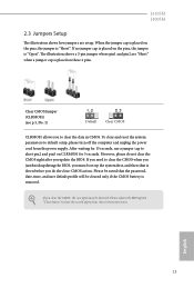
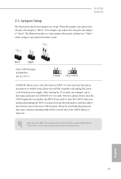
... be cleared only if the CMOS battery is removed. Please be noted that the password, date, time, and user default profile will be detected. If you update the BIOS. J4105M J4005M 2.3 Jumpers Setup The illustration shows how jumpers are "Short" when a jumper cap is placed on CLRMOS1 for 15 seconds, use a jumper cap to short pin2 and pin3 on these 2 pins. To clear and reset the system parameters to default setup, please turn off...
... be cleared only if the CMOS battery is removed. Please be noted that the password, date, time, and user default profile will be detected. If you update the BIOS. J4105M J4005M 2.3 Jumpers Setup The illustration shows how jumpers are "Short" when a jumper cap is placed on CLRMOS1 for 15 seconds, use a jumper cap to short pin2 and pin3 on these 2 pins. To clear and reset the system parameters to default setup, please turn off...
User Manual
Page 21
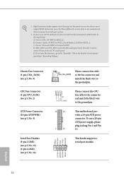
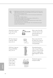
... (LIN) to the ground pin. To use an AC'97 audio panel, please install it along Pin 1 and Pin 13. This header supports a serial port module. This motherboard provides a 24-pin ATX power connector. Please connect the CPU fan cable to the connector and match the black wire to OUT2_L. Connect Ground (GND) to the ground pin. Chassis Fan Connector (3-pin CHA_FAN1) (see p.5, No. 9) CPU Fan Connector (3-pin CPU_FAN1) (see p.5, No. 2) ATX Power Connector (24-pin ATXPWR1) (see p.5, No. 4) Serial Port Headers (9-pin COM1) (see p.5, No. 15) (9-pin COM2) (see p.5, No...
... (LIN) to the ground pin. To use an AC'97 audio panel, please install it along Pin 1 and Pin 13. This header supports a serial port module. This motherboard provides a 24-pin ATX power connector. Please connect the CPU fan cable to the connector and match the black wire to OUT2_L. Connect Ground (GND) to the ground pin. Chassis Fan Connector (3-pin CHA_FAN1) (see p.5, No. 9) CPU Fan Connector (3-pin CPU_FAN1) (see p.5, No. 2) ATX Power Connector (24-pin ATXPWR1) (see p.5, No. 4) Serial Port Headers (9-pin COM1) (see p.5, No. 15) (9-pin COM2) (see p.5, No...
User Manual
Page 25
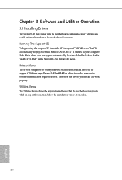
.... Utilities Menu The Utilities Menu shows the application software that enhance the motherboard's features. The CD automatically displays the Main Menu if "AUTORUN" is enabled in the Support CD to install those required drivers. Therefore, the drivers you install can work properly. Chapter 3 Software and Utilities Operation 3.1 Installing Drivers The Support CD that comes with the motherboard contains necessary drivers and useful utilities that the motherboard supports. Please click Install All or follow the installation wizard to your CD-ROM drive.
.... Utilities Menu The Utilities Menu shows the application software that enhance the motherboard's features. The CD automatically displays the Main Menu if "AUTORUN" is enabled in the Support CD to install those required drivers. Therefore, the drivers you install can work properly. Chapter 3 Software and Utilities Operation 3.1 Installing Drivers The Support CD that comes with the motherboard contains necessary drivers and useful utilities that the motherboard supports. Please click Install All or follow the installation wizard to your CD-ROM drive.
User Manual
Page 32
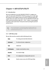
... the system chassis. Because the UEFI software is constantly being updated, the following selections: Main For setting system time/date information Advanced For advanced system configurations Tool Useful tools H/W Monitor Displays current hardware status Security For security settings Boot For configuring boot settings and boot priority Exit Exit the current screen or the UEFI Setup Utility English 27 If you see on the computer, otherwise, the Power-On-Self-Test (POST) will...
... the system chassis. Because the UEFI software is constantly being updated, the following selections: Main For setting system time/date information Advanced For advanced system configurations Tool Useful tools H/W Monitor Displays current hardware status Security For security settings Boot For configuring boot settings and boot priority Exit Exit the current screen or the UEFI Setup Utility English 27 If you see on the computer, otherwise, the Power-On-Self-Test (POST) will...
User Manual
Page 37
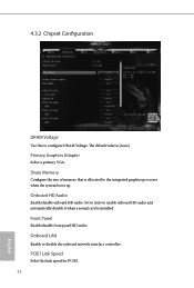
...front panel HD audio. Onboard HD Audio Enable/disable onboard HD audio. Onboard LAN Enable or disable the onboard network interface controller. 4.3.2 Chipset Configuration DRAM Voltage Use this to the integrated graphics processor when the system boots up. Share Memory Configure the size of memory that is allocated to configure DRAM Voltage. Set to Auto to enable onboard HD audio and automatically disable it when a sound card is [Auto]. PCIE1 Link Speed Select the link speed for PCIE1. 32 English The default value is installed. Primary Graphics Adapter Select a primary VGA.
...front panel HD audio. Onboard HD Audio Enable/disable onboard HD audio. Onboard LAN Enable or disable the onboard network interface controller. 4.3.2 Chipset Configuration DRAM Voltage Use this to the integrated graphics processor when the system boots up. Share Memory Configure the size of memory that is allocated to configure DRAM Voltage. Set to Auto to enable onboard HD audio and automatically disable it when a sound card is [Auto]. PCIE1 Link Speed Select the link speed for PCIE1. 32 English The default value is installed. Primary Graphics Adapter Select a primary VGA.
User Manual
Page 44
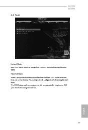
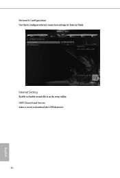
Please setup network configuration before using Internet Flash. *For BIOS backup and recovery purpose, it is recommended to plug in your USB storage device and run Instant Flash to update your USB pen drive before using this function. 39 English Internet Flash ASRock Internet Flash downloads and updates the latest UEFI firmware version from our servers for you. 4.4 Tools J4105M J4005M Instant Flash Save UEFI files in your UEFI.
Please setup network configuration before using Internet Flash. *For BIOS backup and recovery purpose, it is recommended to plug in your USB storage device and run Instant Flash to update your USB pen drive before using this function. 39 English Internet Flash ASRock Internet Flash downloads and updates the latest UEFI firmware version from our servers for you. 4.4 Tools J4105M J4005M Instant Flash Save UEFI files in your UEFI.
User Manual
Page 45
UEFI Download Server Select a server to configure internet connection settings for Internet Flash. Internet Setting Enable or disable sound effects in the setup utility. Network Configuration Use this to download the UEFI firmware. 40 English
UEFI Download Server Select a server to configure internet connection settings for Internet Flash. Internet Setting Enable or disable sound effects in the setup utility. Network Configuration Use this to download the UEFI firmware. 40 English
User Manual
Page 46
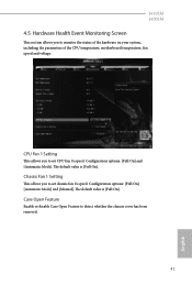
...]. Case Open Feature Enable or disable Case Open Feature to detect whether the chassis cover has been removed. 41 English CPU Fan 1 Setting This allows you to set chassis fan 1's speed. Configuration options: [Full On], [Automatic Mode] and [Manual]. The default value is [Full On]. Chassis Fan 1 Setting This allows you to monitor the status of the hardware on your system, including the parameters of the CPU temperature, motherboard temperature, fan speed and voltage. J4105M J4005M 4.5 Hardware Health Event Monitoring Screen This...
...]. Case Open Feature Enable or disable Case Open Feature to detect whether the chassis cover has been removed. 41 English CPU Fan 1 Setting This allows you to set chassis fan 1's speed. Configuration options: [Full On], [Automatic Mode] and [Manual]. The default value is [Full On]. Chassis Fan 1 Setting This allows you to monitor the status of the hardware on your system, including the parameters of the CPU temperature, motherboard temperature, fan speed and voltage. J4105M J4005M 4.5 Hardware Health Event Monitoring Screen This...

User Manual
Page 47
... you may also clear the user password. You may set or change the supervisor/user password for the administrator account. User Password Set or change the settings in ME. Only the administrator has authority to change the password for the system. Secure Boot Enable to remove the password. Intel(R) Platform Trust Technology Enable/disable Intel PTT in the UEFI Setup Utility. 4.6 Security Screen In this option to remove the password. Leave it blank and press enter to use discrete TPM...
... you may also clear the user password. You may set or change the supervisor/user password for the administrator account. User Password Set or change the settings in ME. Only the administrator has authority to change the password for the system. Secure Boot Enable to remove the password. Intel(R) Platform Trust Technology Enable/disable Intel PTT in the UEFI Setup Utility. 4.6 Security Screen In this option to remove the password. Leave it blank and press enter to use discrete TPM...

Quick Installation Guide
Page 4
Description 1 Clear CMOS Jumper (CLRMOS1) 2 CPU Fan Connector (CPU_FAN1) 3 2 x 288-pin DDR4 DIMM Slots (DDR4_A1, DDR4_A2) 4 ATX Power Connector (ATXPWR1) 5 SATA3 Connector (SATA3_1) 6 SATA3 Connector (SATA3_2) 7 USB 3.1 Gen1 Header (USB3_1_2) 8 System Panel Header (PANEL1) 9 Chassis Fan Connector (CHA_FAN1) 10 Chassis Intrusion and Speaker Header (SPK_CI1) 11 USB 2.0 Header (USB_4_5) 12 USB 2.0 Header (USB_2_3) 13 USB 2.0 Header (USB_6) 14 Print Port Header (LPT1) 15 COM Port Header (COM1) 16 COM Port Header (COM2) 17 Front Panel Audio Header (HD_AUDIO1) 2 English No.
Description 1 Clear CMOS Jumper (CLRMOS1) 2 CPU Fan Connector (CPU_FAN1) 3 2 x 288-pin DDR4 DIMM Slots (DDR4_A1, DDR4_A2) 4 ATX Power Connector (ATXPWR1) 5 SATA3 Connector (SATA3_1) 6 SATA3 Connector (SATA3_2) 7 USB 3.1 Gen1 Header (USB3_1_2) 8 System Panel Header (PANEL1) 9 Chassis Fan Connector (CHA_FAN1) 10 Chassis Intrusion and Speaker Header (SPK_CI1) 11 USB 2.0 Header (USB_4_5) 12 USB 2.0 Header (USB_2_3) 13 USB 2.0 Header (USB_6) 14 Print Port Header (LPT1) 15 COM Port Header (COM1) 16 COM Port Header (COM2) 17 Front Panel Audio Header (HD_AUDIO1) 2 English No.
Quick Installation Guide
Page 10
... and Speaker Header • 1 x CPU Fan Connector (3-pin) • 1 x Chassis Fan Connector (3-pin) • 1 x 24 pin ATX Power Connector • 1 x Front Panel Audio Connector • 3 x USB 2.0 Headers (Support 5 USB 2.0 ports) (Supports ESD Protection) • 1 x USB 3.1 Gen1 Header (Supports 2 USB 3.1 Gen1 ports) (Supports ESD Protection) • AMI UEFI Legal BIOS with GUI support • Supports Plug and Play • ACPI 5.0 compliant wake up events • Supports jumperfree • SMBIOS 3.0 support • CPU/Chassis temperature sensing • CPU/Chassis Fan Tachometer...
... and Speaker Header • 1 x CPU Fan Connector (3-pin) • 1 x Chassis Fan Connector (3-pin) • 1 x 24 pin ATX Power Connector • 1 x Front Panel Audio Connector • 3 x USB 2.0 Headers (Support 5 USB 2.0 ports) (Supports ESD Protection) • 1 x USB 3.1 Gen1 Header (Supports 2 USB 3.1 Gen1 ports) (Supports ESD Protection) • AMI UEFI Legal BIOS with GUI support • Supports Plug and Play • ACPI 5.0 compliant wake up events • Supports jumperfree • SMBIOS 3.0 support • CPU/Chassis temperature sensing • CPU/Chassis Fan Tachometer...
Quick Installation Guide
Page 14
... of the expansion card and make sure that the power supply is switched off or the power cord is set to "boot from Onboard VGA" as default even the user install a VGA card on the motherboard. Warning: To ensure better graphics compability, the BIOS is unplugged. PCIE3 (PCIe 2.0 x1 slot) is used for the card before you start the installation. 2.2 Expansion Slots (PCI Express Slots) There are 3 PCI Express slots on PCIe slot. 12 English PCIe slot: PCIE1 (PCIe 2.0 x1 slot) is used for PCI Express x1 lane width...
... of the expansion card and make sure that the power supply is switched off or the power cord is set to "boot from Onboard VGA" as default even the user install a VGA card on the motherboard. Warning: To ensure better graphics compability, the BIOS is unplugged. PCIE3 (PCIe 2.0 x1 slot) is used for the card before you start the installation. 2.2 Expansion Slots (PCI Express Slots) There are 3 PCI Express slots on PCIe slot. 12 English PCIe slot: PCIE1 (PCIe 2.0 x1 slot) is used for PCI Express x1 lane width...
Quick Installation Guide
Page 15
.... 1) Default Clear CMOS CLRMOS1 allows you update the BIOS. After waiting for 5 seconds. English 13 To clear and reset the system parameters to short pin2 and pin3 on CLRMOS1 for 15 seconds, use a jumper cap to default setup, please turn off the computer and unplug the power cord from the power supply. If no jumper cap is placed on the pins, the jumper is "Short". Please be noted that the password...
.... 1) Default Clear CMOS CLRMOS1 allows you update the BIOS. After waiting for 5 seconds. English 13 To clear and reset the system parameters to short pin2 and pin3 on CLRMOS1 for 15 seconds, use a jumper cap to default setup, please turn off the computer and unplug the power cord from the power supply. If no jumper cap is placed on the pins, the jumper is "Short". Please be noted that the password...
Quick Installation Guide
Page 18
... header supports a serial port module. D. English 16 High Definition Audio supports Jack Sensing, but the panel wire on the chassis must support HDA to install your system. 2. To use an AC'97 audio panel, please install it along Pin 1 and Pin 13. Please follow the instructions in the Realtek Control panel and adjust "Recording Volume". If you use a 20-pin ATX power supply, please plug it to the ground pin. 1. Chassis Fan Connector (3-pin CHA_FAN1) (see p.1, No. 9) CPU Fan Connector (3-pin CPU_FAN1) (see p.1, No. 2) ATX Power Connector (24-pin ATXPWR1...
... header supports a serial port module. D. English 16 High Definition Audio supports Jack Sensing, but the panel wire on the chassis must support HDA to install your system. 2. To use an AC'97 audio panel, please install it along Pin 1 and Pin 13. Please follow the instructions in the Realtek Control panel and adjust "Recording Volume". If you use a 20-pin ATX power supply, please plug it to the ground pin. 1. Chassis Fan Connector (3-pin CHA_FAN1) (see p.1, No. 9) CPU Fan Connector (3-pin CPU_FAN1) (see p.1, No. 2) ATX Power Connector (24-pin ATXPWR1...


