User Manual
Page 4
... 1 1.1 Package Contents 1 1.2 Specifications 2 1.3 Motherboard Layout 5 1.4 I/O Panel 7 Chapter 2 Installation 9 2.1 Installing Memory Modules (DIMM) 10 2.2 Expansion Slot (PCI Express Slot) 12 2.3 Jumpers Setup 13 2.4 Onboard Headers and Connectors 14 Chapter 3 Software and Utilities Operation 18 3.1 Installing Drivers 18 3.2 ASRock Live Update & APP Shop 19 3.2.1 UI Overview 19 3.2.2 Apps 20 3.2.3 BIOS & Drivers 23 3.2.4 Setting 24 Chapter 4 UEFI SETUP UTILITY 25 4.1 Introduction 25 4.1.1 UEFI Menu Bar 25 4.1.2 Navigation Keys 26 4.2 Main Screen 27
... 1 1.1 Package Contents 1 1.2 Specifications 2 1.3 Motherboard Layout 5 1.4 I/O Panel 7 Chapter 2 Installation 9 2.1 Installing Memory Modules (DIMM) 10 2.2 Expansion Slot (PCI Express Slot) 12 2.3 Jumpers Setup 13 2.4 Onboard Headers and Connectors 14 Chapter 3 Software and Utilities Operation 18 3.1 Installing Drivers 18 3.2 ASRock Live Update & APP Shop 19 3.2.1 UI Overview 19 3.2.2 Apps 20 3.2.3 BIOS & Drivers 23 3.2.4 Setting 24 Chapter 4 UEFI SETUP UTILITY 25 4.1 Introduction 25 4.1.1 UEFI Menu Bar 25 4.1.2 Navigation Keys 26 4.2 Main Screen 27
User Manual
Page 6
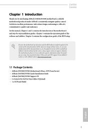
.../J3355M Quick Installation Guide • ASRock J3455M/J3355M Support CD • 2 x Serial ATA (SATA) Data Cables (Optional) • 1 x I/O Panel Shield 1 English It delivers excellent performance with robust design conforming to ASRock's commitment to change without further notice. Because the motherboard specifications and the BIOS software might be available on ASRock's website as well. In this documentation occur, the updated version will be subject to quality and endurance. Chapter 4 contains the configuration guide...
.../J3355M Quick Installation Guide • ASRock J3455M/J3355M Support CD • 2 x Serial ATA (SATA) Data Cables (Optional) • 1 x I/O Panel Shield 1 English It delivers excellent performance with robust design conforming to ASRock's commitment to change without further notice. Because the motherboard specifications and the BIOS software might be available on ASRock's website as well. In this documentation occur, the updated version will be subject to quality and endurance. Chapter 4 contains the configuration guide...
User Manual
Page 7
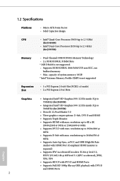
...-ray (BD) playback with max. capacity of system memory: 16GB * Intel® Extreme Memory Profile (XMP) is not supported. • Supports DDR3/DDR3L 1866/1600/1333 non-ECC, un- resolution up to 700MHz) (for J3355M) Memory • Dual Channel DDR3/DDR3L Memory Technology • 2 x DDR3/DDR3L DIMM Slots * 2GB DRAM is not supported Expansion Slot • 1 x PCI Express 2.0 x16 Slot (PCIE2: x1 mode) • 2 x PCI Express 2.0 x1 Slots Graphics • Integrated Intel®...
...-ray (BD) playback with max. capacity of system memory: 16GB * Intel® Extreme Memory Profile (XMP) is not supported. • Supports DDR3/DDR3L 1866/1600/1333 non-ECC, un- resolution up to 700MHz) (for J3355M) Memory • Dual Channel DDR3/DDR3L Memory Technology • 2 x DDR3/DDR3L DIMM Slots * 2GB DRAM is not supported Expansion Slot • 1 x PCI Express 2.0 x16 Slot (PCIE2: x1 mode) • 2 x PCI Express 2.0 x1 Slots Graphics • Integrated Intel®...
User Manual
Page 8
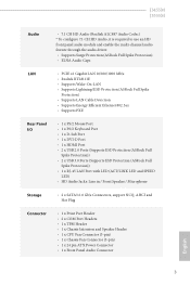
...8226; 2 x USB 3.0 Ports (Supports ESD Protection (ASRock Full Spike Protection)) • 1 x RJ-45 LAN Port with LED (ACT/LINK LED and SPEED LED) • HD Audio Jacks: Line in / Front Speaker / Microphone Storage • 2 x SATA3 6.0 Gb/s Connectors, support NCQ, AHCI and Hot Plug Connector • 1 x Print Port Header • 2 x COM Port Headers • 1 x TPM Header • 1 x Chassis Intrusion and Speaker Header • 1 x CPU Fan Connector (3-pin) • 1 x Chassis Fan Connector (3-pin) • 1 x 24 pin ATX Power Connector • 1 x Front Panel Audio Connector English 3
...8226; 2 x USB 3.0 Ports (Supports ESD Protection (ASRock Full Spike Protection)) • 1 x RJ-45 LAN Port with LED (ACT/LINK LED and SPEED LED) • HD Audio Jacks: Line in / Front Speaker / Microphone Storage • 2 x SATA3 6.0 Gb/s Connectors, support NCQ, AHCI and Hot Plug Connector • 1 x Print Port Header • 2 x COM Port Headers • 1 x TPM Header • 1 x Chassis Intrusion and Speaker Header • 1 x CPU Fan Connector (3-pin) • 1 x Chassis Fan Connector (3-pin) • 1 x 24 pin ATX Power Connector • 1 x Front Panel Audio Connector English 3
User Manual
Page 9
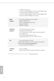
... Feature • AMI UEFI Legal BIOS with GUI support • Supports Plug and Play • ACPI 5.0 compliant wake up events • Supports jumperfree • SMBIOS 2.7 support Hardware Monitor • CPU/Chassis temperature sensing • CPU/Chassis Fan Tachometer • CPU/Chassis Quiet Fan (Auto adjust chassis fan speed by CPU temperature) • CPU/Chassis Fan multi-speed control • Voltage monitoring: +12V, +5V, +3.3V, CPU Vcore OS • Microsoft® Windows® 10 64-bit * For the updated Windows® 10 driver, please visit ASRock's website for details...
... Feature • AMI UEFI Legal BIOS with GUI support • Supports Plug and Play • ACPI 5.0 compliant wake up events • Supports jumperfree • SMBIOS 2.7 support Hardware Monitor • CPU/Chassis temperature sensing • CPU/Chassis Fan Tachometer • CPU/Chassis Quiet Fan (Auto adjust chassis fan speed by CPU temperature) • CPU/Chassis Fan multi-speed control • Voltage monitoring: +12V, +5V, +3.3V, CPU Vcore OS • Microsoft® Windows® 10 64-bit * For the updated Windows® 10 driver, please visit ASRock's website for details...
User Manual
Page 14
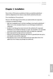
... on a carpet. Doing so may cause physical injuries to you install the motherboard, study the configuration of the following precautions before you install motherboard components or change any motherboard settings. • Make sure to use a grounded wrist strap or touch a safety grounded object before installing or removing the motherboard. J3455M J3355M Chapter 2 Installation This is a Micro ATX form factor motherboard. Failure to do so may damage the...
... on a carpet. Doing so may cause physical injuries to you install the motherboard, study the configuration of the following precautions before you install motherboard components or change any motherboard settings. • Make sure to use a grounded wrist strap or touch a safety grounded object before installing or removing the motherboard. J3455M J3355M Chapter 2 Installation This is a Micro ATX form factor motherboard. Failure to do so may damage the...

User Manual
Page 17
... BIOS is set to "boot from Onboard VGA" as default even the user install a VGA card on the motherboard. PCIE2 (PCIe 2.0 x16 slot) is used for the card before you start the installation. PCIE3 (PCIe 2.0 x1 slot) is used for PCI Express cards with x1 lane width cards. Please read the documentation of the expansion card and make sure that the power supply is switched off or the power cord is used for PCI Express x16 lane width graphics cards. 2.2 Expansion Slot (PCI Express Slot) There are three PCI Express slots...
... BIOS is set to "boot from Onboard VGA" as default even the user install a VGA card on the motherboard. PCIE2 (PCIe 2.0 x16 slot) is used for the card before you start the installation. PCIE3 (PCIe 2.0 x1 slot) is used for PCI Express cards with x1 lane width cards. Please read the documentation of the expansion card and make sure that the power supply is switched off or the power cord is used for PCI Express x16 lane width graphics cards. 2.2 Expansion Slot (PCI Express Slot) There are three PCI Express slots...
User Manual
Page 18
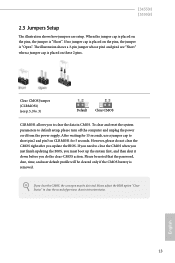
... you update the BIOS. English 13 J3455M J3355M 2.3 Jumpers Setup The illustration shows how jumpers are "Short" when a jumper cap is placed on these 2 pins. Clear CMOS Jumper (CLRMOS1) (see p.5, No. 3) Default Clear CMOS CLRMOS1 allows you to default setup, please turn off the computer and unplug the power cord from the power supply. If you do not clear the CMOS right after you clear the CMOS, the case open may be cleared only if the CMOS battery is removed...
... you update the BIOS. English 13 J3455M J3355M 2.3 Jumpers Setup The illustration shows how jumpers are "Short" when a jumper cap is placed on these 2 pins. Clear CMOS Jumper (CLRMOS1) (see p.5, No. 3) Default Clear CMOS CLRMOS1 allows you to default setup, please turn off the computer and unplug the power cord from the power supply. If you do not clear the CMOS right after you clear the CMOS, the case open may be cleared only if the CMOS battery is removed...

User Manual
Page 19
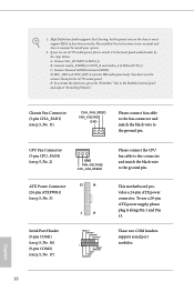
... system is on the chassis front panel. The LED is in S1/S3 sleep state. PWRBTN (Power Switch): Connect to the pin assignments below. A front panel module mainly consists of power switch, reset switch, power LED, hard drive activity LED, speaker and etc. English Chassis Intrusion and Speaker Header (7-pin SPK_CI1) (see p.5, No. 10) PLED+ PLEDPWRBTN# GND 1 GND RESET# GND HDLEDHDLED+ Connect the power switch, reset switch and system status indicator on the chassis to this header. 2.4 Onboard Headers and Connectors Onboard headers and connectors are matched correctly...
... system is on the chassis front panel. The LED is in S1/S3 sleep state. PWRBTN (Power Switch): Connect to the pin assignments below. A front panel module mainly consists of power switch, reset switch, power LED, hard drive activity LED, speaker and etc. English Chassis Intrusion and Speaker Header (7-pin SPK_CI1) (see p.5, No. 10) PLED+ PLEDPWRBTN# GND 1 GND RESET# GND HDLEDHDLED+ Connect the power switch, reset switch and system status indicator on the chassis to this header. 2.4 Onboard Headers and Connectors Onboard headers and connectors are matched correctly...
User Manual
Page 21
...). High Definition Audio supports Jack Sensing, but the panel wire on the chassis must support HDA to MIC2_L. MIC_RET and OUT_RET are for the AC'97 audio panel. E. This motherboard provides a 24-pin ATX power connector. Connect Mic_IN (MIC) to function correctly. To activate the front mic, go to the ground pin. B. D. CPU Fan Connector (3-pin CPU_FAN1) (see p.5, No. 2) GND FAN_VOLTAGE CPU_FAN_SPEED ATX Power Connector (24-pin ATXPWR1) (see p.5, No. 5) 12 24 1 13 Serial Port Header (9-pin COM1...
...). High Definition Audio supports Jack Sensing, but the panel wire on the chassis must support HDA to MIC2_L. MIC_RET and OUT_RET are for the AC'97 audio panel. E. This motherboard provides a 24-pin ATX power connector. Connect Mic_IN (MIC) to function correctly. To activate the front mic, go to the ground pin. B. D. CPU Fan Connector (3-pin CPU_FAN1) (see p.5, No. 2) GND FAN_VOLTAGE CPU_FAN_SPEED ATX Power Connector (24-pin ATXPWR1) (see p.5, No. 5) 12 24 1 13 Serial Port Header (9-pin COM1...
User Manual
Page 23
... motherboard contains necessary drivers and useful utilities that the motherboard supports. The CD automatically displays the Main Menu if "AUTORUN" is enabled in the Support CD to install it. Therefore, the drivers you install can work properly. To improve Windows 7 compatibility, please download and install the following hot fix provided by Microsoft. Drivers Menu The drivers compatible to your system will be auto-detected and listed on the file "ASRSETUP.EXE" in your CD-ROM drive. Please click Install...
... motherboard contains necessary drivers and useful utilities that the motherboard supports. The CD automatically displays the Main Menu if "AUTORUN" is enabled in the Support CD to install it. Therefore, the drivers you install can work properly. To improve Windows 7 compatibility, please download and install the following hot fix provided by Microsoft. Drivers Menu The drivers compatible to your system will be auto-detected and listed on the file "ASRSETUP.EXE" in your CD-ROM drive. Please click Install...

User Manual
Page 24
... connected to the Internet to download apps from the ASRock Live Update & APP Shop. 3.2.1 UI Overview Category Panel Hot News Information Panel Category Panel: The category panel contains several category tabs or buttons that when selected the information panel below displays the relative information. Double-click utility. With ASRock APP Shop, you can quickly and easily install various apps and support utilities, such as USB Key, XFast LAN, XFast RAM...
... connected to the Internet to download apps from the ASRock Live Update & APP Shop. 3.2.1 UI Overview Category Panel Hot News Information Panel Category Panel: The category panel contains several category tabs or buttons that when selected the information panel below displays the relative information. Double-click utility. With ASRock APP Shop, you can quickly and easily install various apps and support utilities, such as USB Key, XFast LAN, XFast RAM...
User Manual
Page 30
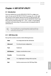
... the UEFI SETUP UTILITY by pressing the reset button on your system. You may not exactly match what you power on . J3455M J3355M Chapter 4 UEFI SETUP UTILITY 4.1 Introduction This section explains how to use the UEFI SETUP UTILITY to enter the UEFI SETUP UTILITY after POST, restart the system by pressing + + , or by pressing or right after you see on the system chassis. Because the UEFI software is constantly being updated, the following UEFI setup screens...
... the UEFI SETUP UTILITY by pressing the reset button on your system. You may not exactly match what you power on . J3455M J3355M Chapter 4 UEFI SETUP UTILITY 4.1 Introduction This section explains how to use the UEFI SETUP UTILITY to enter the UEFI SETUP UTILITY after POST, restart the system by pressing + + , or by pressing or right after you see on the system chassis. Because the UEFI software is constantly being updated, the following UEFI setup screens...

User Manual
Page 35
...4.3.2 Chipset Configuration DRAM Frequency If [Auto] is set to [Onboard] (boot from onboard VGA). DRAM Voltage (1.50V) Use this to enable onboard HD audio and automatically disable it when a sound card is installed. Primary Graphics Adapter Select a primary VGA. *To ensure better graphics compatibility, the default is selected, the motherboard will detect the memory module(s) inserted and assign the appropriate frequency automatically. Front Panel Enable/disable front panel HD audio. 30 English The default value is allocated to the integrated graphics processor when the system boots up...
...4.3.2 Chipset Configuration DRAM Frequency If [Auto] is set to [Onboard] (boot from onboard VGA). DRAM Voltage (1.50V) Use this to enable onboard HD audio and automatically disable it when a sound card is installed. Primary Graphics Adapter Select a primary VGA. *To ensure better graphics compatibility, the default is selected, the motherboard will detect the memory module(s) inserted and assign the appropriate frequency automatically. Front Panel Enable/disable front panel HD audio. 30 English The default value is allocated to the integrated graphics processor when the system boots up...

User Manual
Page 36
... LED By enabling Good Night LED, the Power LEDs will be switched off when the system is selected, the power will also automatically switch off when the power recovers. Restore on . Deep S5 Configure deep sleep mode for PCIE2. If [Power On] is shut down. It will remain off the Power and Keyboard LEDs when the system enters into Standby/Hibernation mode. 31 English J3455M J3355M Onboard LAN Enable or disable the onboard network interface controller...
... LED By enabling Good Night LED, the Power LEDs will be switched off when the system is selected, the power will also automatically switch off when the power recovers. Restore on . Deep S5 Configure deep sleep mode for PCIE2. If [Power On] is shut down. It will remain off the Power and Keyboard LEDs when the system enters into Standby/Hibernation mode. 31 English J3455M J3355M Onboard LAN Enable or disable the onboard network interface controller...

User Manual
Page 38
Serial Port 2 Enable or disable the Serial port 2. 4.3.4 Super IO Configuration J3455M J3355M Serial Port 1 Enable or disable the Serial port 1. Change Settings Select the address of the Serial port. Serial Port Address Select the address of the Parallel port. Parallel Port Enable or disable the Parallel port. Serial Port Address Select the address of the Serial port. Device Mode Select the device mode according to your connected device. 33 English
Serial Port 2 Enable or disable the Serial port 2. 4.3.4 Super IO Configuration J3455M J3355M Serial Port 1 Enable or disable the Serial port 1. Change Settings Select the address of the Serial port. Serial Port Address Select the address of the Parallel port. Parallel Port Enable or disable the Parallel port. Serial Port Address Select the address of the Serial port. Device Mode Select the device mode according to your connected device. 33 English
User Manual
Page 43
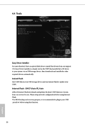
DHCP (Auto IP), Auto ASRock Internet Flash downloads and updates the latest UEFI firmware version from our support CD, Easy Driver Installer is recommended to plug in your USB pen drive before using this function. 38 English Instant Flash Save UEFI files in the UEFI that don't have an optical disk drive to install the drivers from our servers for you. 4.4 Tools Easy Driver Installer For users that installs the LAN driver to update your UEFI. Please setup network configuration before using Internet Flash. *For BIOS backup and recovery purpose...
DHCP (Auto IP), Auto ASRock Internet Flash downloads and updates the latest UEFI firmware version from our support CD, Easy Driver Installer is recommended to plug in your USB pen drive before using this function. 38 English Instant Flash Save UEFI files in the UEFI that don't have an optical disk drive to install the drivers from our servers for you. 4.4 Tools Easy Driver Installer For users that installs the LAN driver to update your UEFI. Please setup network configuration before using Internet Flash. *For BIOS backup and recovery purpose...

User Manual
Page 44
English 39 UEFI Download Server Select a server to configure internet connection settings for Internet Flash. Network Configuration Use this to download the UEFI firmware. J3455M J3355M Internet Setting Enable or disable sound effects in the setup utility.
English 39 UEFI Download Server Select a server to configure internet connection settings for Internet Flash. Network Configuration Use this to download the UEFI firmware. J3455M J3355M Internet Setting Enable or disable sound effects in the setup utility.
User Manual
Page 45
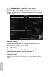
... is [Full On]. Configuration options: [Full On], [Automatic Mode] and [Manual]. Configuration options: [Full On] and [Automatic Mode]. The default value is [Full On]. CPU Fan 1 Setting This allows you to set chassis fan 1's speed. Case Open Feature Enable or disable Case Open Feature to monitor the status of the hardware on your system, including the parameters of the CPU temperature, motherboard temperature, fan speed and voltage. Chassis Fan 1 Setting This allows you to set CPU fan 1's speed. 4.5 Hardware Health Event Monitoring Screen This section allows...
... is [Full On]. Configuration options: [Full On], [Automatic Mode] and [Manual]. Configuration options: [Full On] and [Automatic Mode]. The default value is [Full On]. CPU Fan 1 Setting This allows you to set chassis fan 1's speed. Case Open Feature Enable or disable Case Open Feature to monitor the status of the hardware on your system, including the parameters of the CPU temperature, motherboard temperature, fan speed and voltage. Chassis Fan 1 Setting This allows you to set CPU fan 1's speed. 4.5 Hardware Health Event Monitoring Screen This section allows...
User Manual
Page 46
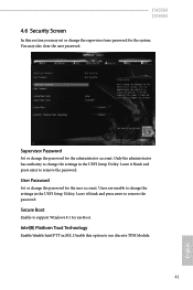
... enter to remove the password. Only the administrator has authority to change the settings in ME. J3455M J3355M 4.6 Security Screen In this option to use discrete TPM Module. 41 English You may set or change the password for the user account. Intel(R) Platform Trust Technology Enable/disable Intel PTT in the UEFI Setup Utility. Users are unable to support Windows 8.1 Secure Boot. Disable this section you may also clear the user password. Supervisor Password Set or change the settings in the UEFI Setup Utility...
... enter to remove the password. Only the administrator has authority to change the settings in ME. J3455M J3355M 4.6 Security Screen In this option to use discrete TPM Module. 41 English You may set or change the password for the user account. Intel(R) Platform Trust Technology Enable/disable Intel PTT in the UEFI Setup Utility. Users are unable to support Windows 8.1 Secure Boot. Disable this section you may also clear the user password. Supervisor Password Set or change the settings in the UEFI Setup Utility...


