

User Manual
Page 4
... 1.1 Package Contents 1 1.2 Specifications 2 1.3 Motherboard Layout 5 1.4 I/O Panel 7 Chapter 2 Installation 8 2.1 Installing Memory Modules (SO-DIMM) 9 2.2 Expansion Slots (PCI Express Slots) 11 2.3 Jumpers Setup 12 2.4 Onboard Headers and Connectors 13 Chapter 3 Software and Utilities Operation 19 3.1 Installing Drivers 19 3.2 ASRock Live Update & APP Shop 20 3.2.1 UI Overview 20 3.2.2 Apps 21 3.2.3 BIOS & Drivers 24 3.2.4 Setting 25 Chapter 4 UEFI SETUP UTILITY 29 4.1 Introduction 29 4.1.1 UEFI Menu Bar 29 4.1.2 Navigation Keys 30 4.2 Main Screen 31
... 1.1 Package Contents 1 1.2 Specifications 2 1.3 Motherboard Layout 5 1.4 I/O Panel 7 Chapter 2 Installation 8 2.1 Installing Memory Modules (SO-DIMM) 9 2.2 Expansion Slots (PCI Express Slots) 11 2.3 Jumpers Setup 12 2.4 Onboard Headers and Connectors 13 Chapter 3 Software and Utilities Operation 19 3.1 Installing Drivers 19 3.2 ASRock Live Update & APP Shop 20 3.2.1 UI Overview 20 3.2.2 Apps 21 3.2.3 BIOS & Drivers 24 3.2.4 Setting 25 Chapter 4 UEFI SETUP UTILITY 29 4.1 Introduction 29 4.1.1 UEFI Menu Bar 29 4.1.2 Navigation Keys 30 4.2 Main Screen 31
User Manual
Page 6
... CPU support list on ASRock's website without notice. Chapter 3 contains the operation guide of the BIOS setup. ASRock website http://www.asrock.com. 1.1 Package Contents • ASRock J3160TM-ITX Motherboard (Thin Mini-ITX Form Factor) • ASRock J3160TM-ITX Quick Installation Guide • ASRock J3160TM-ITX Support CD • 2 x Serial ATA (SATA) Data Cables (Optional) • 1 x SATA 1 to quality and endurance. In case any modifications of this manual, Chapter 1 and 2 contains the introduction of this motherboard, please visit our website for specific...
... CPU support list on ASRock's website without notice. Chapter 3 contains the operation guide of the BIOS setup. ASRock website http://www.asrock.com. 1.1 Package Contents • ASRock J3160TM-ITX Motherboard (Thin Mini-ITX Form Factor) • ASRock J3160TM-ITX Quick Installation Guide • ASRock J3160TM-ITX Support CD • 2 x Serial ATA (SATA) Data Cables (Optional) • 1 x SATA 1 to quality and endurance. In case any modifications of this manual, Chapter 1 and 2 contains the introduction of this motherboard, please visit our website for specific...
User Manual
Page 8
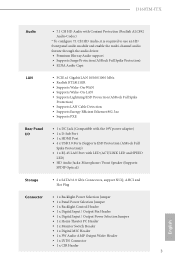
... x DC Jack (Compatible with the 19V power adapter) • 1 x D-Sub Port • 1 x HDMI Port • 4 x USB 3.0 Ports (Supports ESD Protection (ASRock Full Spike Protection)) • 1 x RJ-45 LAN Port with LED (ACT/LINK LED and SPEED LED) • HD Audio Jacks: Microphone / Front Speaker (Supports SPDIF Optical) Storage • 2 x SATA3 6.0 Gb/s Connectors, support NCQ, AHCI and Hot Plug Connector • 1 x Backlight Power Selection Jumper • 1 x Panel Power Selection Jumper • 1 x Backlight Control Header • 1 x Digital Input / Output Pin Header • 1 x Digital...
... x DC Jack (Compatible with the 19V power adapter) • 1 x D-Sub Port • 1 x HDMI Port • 4 x USB 3.0 Ports (Supports ESD Protection (ASRock Full Spike Protection)) • 1 x RJ-45 LAN Port with LED (ACT/LINK LED and SPEED LED) • HD Audio Jacks: Microphone / Front Speaker (Supports SPDIF Optical) Storage • 2 x SATA3 6.0 Gb/s Connectors, support NCQ, AHCI and Hot Plug Connector • 1 x Backlight Power Selection Jumper • 1 x Panel Power Selection Jumper • 1 x Backlight Control Header • 1 x Digital Input / Output Pin Header • 1 x Digital...

User Manual
Page 9
... the updated Windows® 10 driver, please visit ASRock's website for system usage under Windows® 32-bit operating systems. Windows® 64-bit operating systems do not have such limitations. • 1 x COM Port Header • 1 x Power LED Header • 1 x TPM Header • 1 x CPU Fan Connector (4-pin) • 1 x Chassis Fan Connector (4-pin) • 1 x SATA Power Connector • 1 x Internal Power Header • 1 x Front Panel Audio Connector • 1 x Analog Surround Audio Connector • 3 x USB 2.0 Headers (Support 5 USB 2.0 ports) (Supports ESD Protection (ASRock...
... the updated Windows® 10 driver, please visit ASRock's website for system usage under Windows® 32-bit operating systems. Windows® 64-bit operating systems do not have such limitations. • 1 x COM Port Header • 1 x Power LED Header • 1 x TPM Header • 1 x CPU Fan Connector (4-pin) • 1 x Chassis Fan Connector (4-pin) • 1 x SATA Power Connector • 1 x Internal Power Header • 1 x Front Panel Audio Connector • 1 x Analog Surround Audio Connector • 3 x USB 2.0 Headers (Support 5 USB 2.0 ports) (Supports ESD Protection (ASRock...

User Manual
Page 11
...3 SATA3 Connector (SATA3_2) 4 SATA3 Connector (SATA3_1) 5 Monitor Switch Header (MONITOR_SWITCH1) 6 USB 2.0 Header (USB4_5) 7 CPU Fan Connector (CPU_FAN1) 8 USB 3.0 Header (USB3_4_5) 9 Chassis Fan Connector (CHA_FAN1) 10 Consumer Infrared Module Header (CIR1) 11 Power LED Header (PLED1) 12 Backlight Power Jumper (BKT_PWR1) 13 System Panel Header (PANEL1) 14 Panel Power Jumper (PNL_PWR1) 15 LVDS Connector (LVDS1) 16 Backlight Control Header (BLT_VOL1) 17 COM Port Header (COM1) 18 USB 2.0 Header (USB7_8) 19 TPM Header (TPMS1) 20 Clear CMOS Jumper (CLRCMOS1) 21 204-pin DDR3 SO-DIMM Slots (DDR3_B1...
...3 SATA3 Connector (SATA3_2) 4 SATA3 Connector (SATA3_1) 5 Monitor Switch Header (MONITOR_SWITCH1) 6 USB 2.0 Header (USB4_5) 7 CPU Fan Connector (CPU_FAN1) 8 USB 3.0 Header (USB3_4_5) 9 Chassis Fan Connector (CHA_FAN1) 10 Consumer Infrared Module Header (CIR1) 11 Power LED Header (PLED1) 12 Backlight Power Jumper (BKT_PWR1) 13 System Panel Header (PANEL1) 14 Panel Power Jumper (PNL_PWR1) 15 LVDS Connector (LVDS1) 16 Backlight Control Header (BLT_VOL1) 17 COM Port Header (COM1) 18 USB 2.0 Header (USB7_8) 19 TPM Header (TPMS1) 20 Clear CMOS Jumper (CLRCMOS1) 21 204-pin DDR3 SO-DIMM Slots (DDR3_B1...

User Manual
Page 13
... ICs. • Whenever you install motherboard components or change any components, place them on a carpet. Chapter 2 Installation This is a Thin Mini-ITX form factor motherboard. Also remember to use a grounded wrist strap or touch a safety grounded object before you uninstall any motherboard settings. • Make sure to the motherboard's components, NEVER place your chassis to the chassis, please do so may damage...
... ICs. • Whenever you install motherboard components or change any components, place them on a carpet. Chapter 2 Installation This is a Thin Mini-ITX form factor motherboard. Also remember to use a grounded wrist strap or touch a safety grounded object before you uninstall any motherboard settings. • Make sure to the motherboard's components, NEVER place your chassis to the chassis, please do so may damage...
User Manual
Page 16
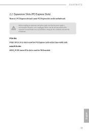
mini-PCIe slot: MINI_PCIE1 (mini-PCIe slot) is unplugged. Please read the documentation of the expansion card and make sure that the power supply is switched off or the power cord is used for PCI Express cards with x1 lane width cards. Before installing an expansion card, please make necessary hardware settings for the card before you start the installation. J3160TM-ITX 2.2 Expansion Slots (PCI Express Slots) There is used for WiFi module. 11 English PCIe slot: PCIE1 (PCIe 2.0 x1 slot) is 1 PCI Express slot and 1 mini-PCI Express slot on the motherboard.
mini-PCIe slot: MINI_PCIE1 (mini-PCIe slot) is unplugged. Please read the documentation of the expansion card and make sure that the power supply is switched off or the power cord is used for PCI Express cards with x1 lane width cards. Before installing an expansion card, please make necessary hardware settings for the card before you start the installation. J3160TM-ITX 2.2 Expansion Slots (PCI Express Slots) There is used for WiFi module. 11 English PCIe slot: PCIE1 (PCIe 2.0 x1 slot) is 1 PCI Express slot and 1 mini-PCI Express slot on the motherboard.

User Manual
Page 18
... cables. A front panel module mainly consists of power switch, reset switch, power LED, hard drive activity LED, speaker and etc. J3160TM-ITX 2.4 Onboard Headers and Connectors Onboard headers and connectors are matched correctly. RESET (Reset Switch): Connect to the pin assignments below. The LED is operating. The LED is reading or writing data. PLED+ PLED+ Please connect the chassis power LED to this header according to the reset switch on when the system is on the chassis front panel. Placing jumper caps over these headers and connectors. System Panel Header (9-pin...
... cables. A front panel module mainly consists of power switch, reset switch, power LED, hard drive activity LED, speaker and etc. J3160TM-ITX 2.4 Onboard Headers and Connectors Onboard headers and connectors are matched correctly. RESET (Reset Switch): Connect to the pin assignments below. The LED is operating. The LED is reading or writing data. PLED+ PLED+ Please connect the chassis power LED to this header according to the reset switch on when the system is on the chassis front panel. Placing jumper caps over these headers and connectors. System Panel Header (9-pin...

User Manual
Page 21
...motherboard provides a 2-pin ATX 19V power connector. CPU Fan Connector (4-pin CPU_FAN1) (see p.5, No. 7) Internal Power Header (2-pin ATX19V_IN1) (see p.5, No. 30) Consumer Infrared Module Header (7-pin CIR1) (see p.5, No. 10) Serial Port Header (9-pin COM1) (see p.5, No. 17) Backlight Control Header (8-pin BLT_VOL1) (see p.5, No. 9) GND +12V CHA_FAN_SPEED FAN_SPEED_CONTROL Please connect fan cable to the fan connector and match the black wire to the ground pin. If you plan to connect a 3-Pin CPU fan, please connect it to connect the remote controller receiver. Chassis Fan Connector...
...motherboard provides a 2-pin ATX 19V power connector. CPU Fan Connector (4-pin CPU_FAN1) (see p.5, No. 7) Internal Power Header (2-pin ATX19V_IN1) (see p.5, No. 30) Consumer Infrared Module Header (7-pin CIR1) (see p.5, No. 10) Serial Port Header (9-pin COM1) (see p.5, No. 17) Backlight Control Header (8-pin BLT_VOL1) (see p.5, No. 9) GND +12V CHA_FAN_SPEED FAN_SPEED_CONTROL Please connect fan cable to the fan connector and match the black wire to the ground pin. If you plan to connect a 3-Pin CPU fan, please connect it to connect the remote controller receiver. Chassis Fan Connector...

User Manual
Page 23
... 5 PWR1 to connect a switch that turns on/ off the LVDS panel display's backlight. TPM Header (17-pin TPMS1) (see p.5, No. 19) F_CLKRUN# SERIRQ# S_PWRDWN# GND LAD1_L LAD2_L SMB_DATA_MAIN SMB_CLK_MAIN GND GND +3VSB LAD0_L +3V LAD3_L TPM_RST# LFRAME#_L CK_33M_TPM 1 This connector supports Trusted Platform Module (TPM) system, which can be used to configure) 4 GPIO4 3 GPIO3 2 GPIO2 1 GPIO1 English 18 Monitor Switch Header (2-pin MONITOR_ SWITCH1...
... 5 PWR1 to connect a switch that turns on/ off the LVDS panel display's backlight. TPM Header (17-pin TPMS1) (see p.5, No. 19) F_CLKRUN# SERIRQ# S_PWRDWN# GND LAD1_L LAD2_L SMB_DATA_MAIN SMB_CLK_MAIN GND GND +3VSB LAD0_L +3V LAD3_L TPM_RST# LFRAME#_L CK_33M_TPM 1 This connector supports Trusted Platform Module (TPM) system, which can be used to configure) 4 GPIO4 3 GPIO3 2 GPIO2 1 GPIO1 English 18 Monitor Switch Header (2-pin MONITOR_ SWITCH1...

User Manual
Page 24
... J3160TM-ITX Chapter 3 Software and Utilities Operation 3.1 Installing Drivers The Support CD that comes with the motherboard contains necessary drivers and useful utilities that the motherboard supports. Click on a specific item then follow the order from top to bottom to your system will be auto-detected and listed on the file "ASRSETUP.EXE" in your CD-ROM drive. The CD automatically displays the Main Menu if "AUTORUN" is enabled in the Support CD to install...
... J3160TM-ITX Chapter 3 Software and Utilities Operation 3.1 Installing Drivers The Support CD that comes with the motherboard contains necessary drivers and useful utilities that the motherboard supports. Click on a specific item then follow the order from top to bottom to your system will be auto-detected and listed on the file "ASRSETUP.EXE" in your CD-ROM drive. The CD automatically displays the Main Menu if "AUTORUN" is enabled in the Support CD to install...

User Manual
Page 31
... Host Controller (xHCI) drivers packed into the ISO file. Then use the new patched Windows® 7 installation USB drive to function properly, please create a Windows® 7 installation disk with the "Win7 USB Patcher". 3.3 Enabling USB Ports for Windows® 7 Installation Intel® Braswell and Skylake has removed their motherboard won't work. You only have an optical disc drive, please find it difficult to disabled after the installation. USB3.0). Please set PS/S Simulator back to install Windows...
... Host Controller (xHCI) drivers packed into the ISO file. Then use the new patched Windows® 7 installation USB drive to function properly, please create a Windows® 7 installation disk with the "Win7 USB Patcher". 3.3 Enabling USB Ports for Windows® 7 Installation Intel® Braswell and Skylake has removed their motherboard won't work. You only have an optical disc drive, please find it difficult to disabled after the installation. USB3.0). Please set PS/S Simulator back to install Windows...
User Manual
Page 32
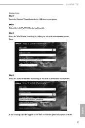
Step 4 Select the "USB Driver Folder" by clicking the red circle as shown as the picture below . J3160TM-ITX Instructions Step 1 Insert the Windows® 7 installation disk or USB drive to your CD-ROM. 27 English Step 2 Extract the tool (Win7 USB Patcher) and launch it. Step 3 Select the "Win7 Folder" from Step1 by clicking the red circle as shown as the picture below . If you are using ASRock's Support CD for the USB 3.0 driver, please select your system.
Step 4 Select the "USB Driver Folder" by clicking the red circle as shown as the picture below . J3160TM-ITX Instructions Step 1 Insert the Windows® 7 installation disk or USB drive to your CD-ROM. 27 English Step 2 Extract the tool (Win7 USB Patcher) and launch it. Step 3 Select the "Win7 Folder" from Step1 by clicking the red circle as shown as the picture below . If you are using ASRock's Support CD for the USB 3.0 driver, please select your system.

User Manual
Page 34
... UEFI software is constantly being updated, the following selections: Main For setting system time/date information Advanced For advanced system configurations Tool Useful tools H/W Monitor Displays current hardware status Security For security settings Boot For configuring boot settings and boot priority Exit Exit the current screen or the UEFI Setup Utility English 29 J3160TM-ITX Chapter 4 UEFI SETUP UTILITY 4.1 Introduction This section explains how to use the UEFI SETUP UTILITY to enter the UEFI SETUP UTILITY after you wish to configure your screen. 4.1.1 UEFI Menu...
... UEFI software is constantly being updated, the following selections: Main For setting system time/date information Advanced For advanced system configurations Tool Useful tools H/W Monitor Displays current hardware status Security For security settings Boot For configuring boot settings and boot priority Exit Exit the current screen or the UEFI Setup Utility English 29 J3160TM-ITX Chapter 4 UEFI SETUP UTILITY 4.1 Introduction This section explains how to use the UEFI SETUP UTILITY to enter the UEFI SETUP UTILITY after you wish to configure your screen. 4.1.1 UEFI Menu...
User Manual
Page 40
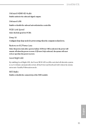
... the power state after a power failure. Good Night LED By enabling Good Night LED, the Power/HDD LEDs will remain off when the system is selected, the system will also automatically switch off the Power and Keyboard LEDs when the system enters into Standby/Hibernation mode. It will start to boot up when the power recovers. Onboard LAN Enable or disable the onboard network interface controller. Deep S5 Configure deep sleep mode for the onboard digital outputs. PCIE1 Link Speed...
... the power state after a power failure. Good Night LED By enabling Good Night LED, the Power/HDD LEDs will remain off when the system is selected, the system will also automatically switch off the Power and Keyboard LEDs when the system enters into Standby/Hibernation mode. It will start to boot up when the power recovers. Onboard LAN Enable or disable the onboard network interface controller. Deep S5 Configure deep sleep mode for the onboard digital outputs. PCIE1 Link Speed...
User Manual
Page 44
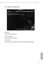
The default value is [Enabled]. 39 English CIR Controller Use this item to enable or disable the CIR controller. Serial Port Address Select the address of the Serial port. 4.3.5 Super IO Configuration J3160TM-ITX Serial Port 1 Enable or disable the Serial port 1.
The default value is [Enabled]. 39 English CIR Controller Use this item to enable or disable the CIR controller. Serial Port Address Select the address of the Serial port. 4.3.5 Super IO Configuration J3160TM-ITX Serial Port 1 Enable or disable the Serial port 1.

User Manual
Page 45
... power on LAN. 4.3.6 ACPI Configuration Suspend to RAM It is recommended to select auto for better performance and to pass WHQL tests. ACPI HPET Table Enable the High Precision Event Timer for ACPI S3 power saving. Set it to By OS to let it be waked up by a PCIE device and enable wake on the system. Ring-In Power On Allow the system to be waked up by onboard COM port...
... power on LAN. 4.3.6 ACPI Configuration Suspend to RAM It is recommended to select auto for better performance and to pass WHQL tests. ACPI HPET Table Enable the High Precision Event Timer for ACPI S3 power saving. Set it to By OS to let it be waked up by a PCIE device and enable wake on the system. Ring-In Power On Allow the system to be waked up by onboard COM port...
User Manual
Page 49
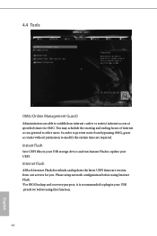
Please setup network configuration before using Internet Flash. *For BIOS backup and recovery purpose, it is recommended to plug in your USB storage device and run Instant Flash to other users. Internet Flash ASRock Internet Flash downloads and updates the latest UEFI firmware version from bypassing OMG, guest accounts without permission to modify the system time are able to prevent users from our servers for you. In order to establish an internet curfew...
Please setup network configuration before using Internet Flash. *For BIOS backup and recovery purpose, it is recommended to plug in your USB storage device and run Instant Flash to other users. Internet Flash ASRock Internet Flash downloads and updates the latest UEFI firmware version from bypassing OMG, guest accounts without permission to modify the system time are able to prevent users from our servers for you. In order to establish an internet curfew...

User Manual
Page 50
Network Configuration Use this to download the UEFI firmware. 45 English UEFI Download Server Select a server to configure internet connection settings for Internet Flash. J3160TM-ITX Internet Setting Enable or disable sound effects in the setup utility.
Network Configuration Use this to download the UEFI firmware. 45 English UEFI Download Server Select a server to configure internet connection settings for Internet Flash. J3160TM-ITX Internet Setting Enable or disable sound effects in the setup utility.

User Manual
Page 53
... Enable to display the boot logo or disable to wait for you may not boot from an USB storage device. Ultra Fast mode is to Clear CMOS or run the Restart to configure the boot settings and the boot priority. In fast mode you to UEFI utility in Windows. Please notice that Ultra Fast mode will boot so fast that the only way to enter this UEFI Setup Utility is only supported by the onboard LAN. 4.7 Boot Screen This section displays...
... Enable to display the boot logo or disable to wait for you may not boot from an USB storage device. Ultra Fast mode is to Clear CMOS or run the Restart to configure the boot settings and the boot priority. In fast mode you to UEFI utility in Windows. Please notice that Ultra Fast mode will boot so fast that the only way to enter this UEFI Setup Utility is only supported by the onboard LAN. 4.7 Boot Screen This section displays...


