

User Manual
Page 2
...in any form or by any means, except duplication of this documentation may be constructed as a commitment by ASRock. ASRock assumes no event shall ASRock, its directors, officers, employees, or agents be registered trademarks or copyrights of such damages arising from any language... may appear in this documentation. CALIFORNIA, USA ONLY The Lithium battery adopted on this motherboard contains Perchlorate, a toxic substance controlled in this documentation, ASRock does not provide warranty of ASRock Inc. Operation is subject to the following two conditions: (1) this device may not...
...in any form or by any means, except duplication of this documentation may be constructed as a commitment by ASRock. ASRock assumes no event shall ASRock, its directors, officers, employees, or agents be registered trademarks or copyrights of such damages arising from any language... may appear in this documentation. CALIFORNIA, USA ONLY The Lithium battery adopted on this motherboard contains Perchlorate, a toxic substance controlled in this documentation, ASRock does not provide warranty of ASRock Inc. Operation is subject to the following two conditions: (1) this device may not...
User Manual
Page 4
Contents Chapter 1 Introduction 1 1.1 Package Contents 1 1.2 Specifications 2 1.3 Motherboard Layout 5 1.4 I/O Panel 7 Chapter 2 Installation 9 2.1 Installing Memory Modules (SO-DIMM) 10 2.2 Expansion Slots (PCI Express Slot) 12 2.3 Jumpers Setup 13 2.4 Onboard Headers and Connectors 14 Chapter 3 Software and Utilities Operation 18 3.1 Installing Drivers 18 3.2 ASRock Live Update & APP Shop 19 3.2.1 UI Overview 19 3.2.2 Apps 20 3.2.3 BIOS & Drivers...
Contents Chapter 1 Introduction 1 1.1 Package Contents 1 1.2 Specifications 2 1.3 Motherboard Layout 5 1.4 I/O Panel 7 Chapter 2 Installation 9 2.1 Installing Memory Modules (SO-DIMM) 10 2.2 Expansion Slots (PCI Express Slot) 12 2.3 Jumpers Setup 13 2.4 Onboard Headers and Connectors 14 Chapter 3 Software and Utilities Operation 18 3.1 Installing Drivers 18 3.2 ASRock Live Update & APP Shop 19 3.2.1 UI Overview 19 3.2.2 Apps 20 3.2.3 BIOS & Drivers...
User Manual
Page 6
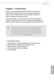
... without notice. It delivers excellent performance with robust design conforming to ASRock's commitment to quality and endurance. ASRock website http://www.asrock.com. 1.1 Package Contents • ASRock J3160B-ITX / J3060B-ITX Motherboard (Mini-ITX Form Factor) • ASRock J3160B-ITX / J3060B-ITX Quick Installation Guide • ASRock J3160B-ITX / J3060B-ITX Support CD • 2 x Serial ATA (SATA) Data Cables (Optional) • 1 x I/O Panel Shield 1 English In case any...
... without notice. It delivers excellent performance with robust design conforming to ASRock's commitment to quality and endurance. ASRock website http://www.asrock.com. 1.1 Package Contents • ASRock J3160B-ITX / J3060B-ITX Motherboard (Mini-ITX Form Factor) • ASRock J3160B-ITX / J3060B-ITX Quick Installation Guide • ASRock J3160B-ITX / J3060B-ITX Support CD • 2 x Serial ATA (SATA) Data Cables (Optional) • 1 x I/O Panel Shield 1 English In case any...
User Manual
Page 10
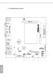
PS2 Mouse PS2 Keyboard COM1 AT X P W R 1 DDR3_B1 VGA1 1.3 Motherboard Layout CPU_FAN1 DDR3_A1 PARALLEL PORT HDMI1 USB 2.0 T: USB0 B: USB1 CMOS Battery USB 3.0 LAN T: USB3 Top: RJ-45 B: USB4 AUDIO CODEC Super I/O HD_AUDIO1 1 PCIE1 COM2 1 CLRMOS1 1 BIOS ROM CI1 1 TPMS1 1 SATA3_2 SPEAKER1 1 SATA3_1 PLED PWRBTN 1 HDLED RESET PANEL1 USB3_1_2 USB2_3 1 USB4_5 1 RoHS Front USB 3.0 Top: LINE IN Center: FRONT Bottom: MIC IN English 5
PS2 Mouse PS2 Keyboard COM1 AT X P W R 1 DDR3_B1 VGA1 1.3 Motherboard Layout CPU_FAN1 DDR3_A1 PARALLEL PORT HDMI1 USB 2.0 T: USB0 B: USB1 CMOS Battery USB 3.0 LAN T: USB3 Top: RJ-45 B: USB4 AUDIO CODEC Super I/O HD_AUDIO1 1 PCIE1 COM2 1 CLRMOS1 1 BIOS ROM CI1 1 TPMS1 1 SATA3_2 SPEAKER1 1 SATA3_1 PLED PWRBTN 1 HDLED RESET PANEL1 USB3_1_2 USB2_3 1 USB4_5 1 RoHS Front USB 3.0 Top: LINE IN Center: FRONT Bottom: MIC IN English 5

User Manual
Page 14
...you handle the components. • Hold components by the edges and do not touch the ICs. • Whenever you install motherboard components or change any components, place them on a carpet. Failure to do not overtighten the screws! Also remember to use a... you uninstall any motherboard settings. • Make sure to the chassis, please do so may damage the motherboard. 9 English Chapter 2 Installation This is a Mini-ITX form factor motherboard. Pre-installation Precautions Take note of your chassis to the motherboard's components, NEVER place your motherboard directly on a ...
...you handle the components. • Hold components by the edges and do not touch the ICs. • Whenever you install motherboard components or change any components, place them on a carpet. Failure to do not overtighten the screws! Also remember to use a... you uninstall any motherboard settings. • Make sure to the chassis, please do so may damage the motherboard. 9 English Chapter 2 Installation This is a Mini-ITX form factor motherboard. Pre-installation Precautions Take note of your chassis to the motherboard's components, NEVER place your motherboard directly on a ...
User Manual
Page 15
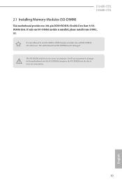
The SO-DIMM only fits in one SO-DIMM module is not allowed to the motherboard and the SO-DIMM if you force the SO-DIMM into a DDR3/DDR3L slot; J3160B-ITX J3060B-ITX 2.1 Installing Memory Modules (SO-DIMM) This motherboard provides two 204-pin DDR3/DDR3L (Double Data Rate 3) SODIMM slots. If only one correct orientation. otherwise, this motherboard and SO-DIMM may be damaged. It will cause permanent damage to install a DDR or DDR2 memory module into the slot at incorrect orientation. 10 English It is installed, please install it into DDR3_ A1.
The SO-DIMM only fits in one SO-DIMM module is not allowed to the motherboard and the SO-DIMM if you force the SO-DIMM into a DDR3/DDR3L slot; J3160B-ITX J3060B-ITX 2.1 Installing Memory Modules (SO-DIMM) This motherboard provides two 204-pin DDR3/DDR3L (Double Data Rate 3) SODIMM slots. If only one correct orientation. otherwise, this motherboard and SO-DIMM may be damaged. It will cause permanent damage to install a DDR or DDR2 memory module into the slot at incorrect orientation. 10 English It is installed, please install it into DDR3_ A1.
User Manual
Page 17
English 12 Please read the documentation of the expansion card and make sure that the power supply is switched off or the power cord is unplugged. PCIe slot: PCIE1 (PCIe 2.0 x1 slot) is 1 PCI Express slot on the motherboard. 2.2 Expansion Slots (PCI Express Slot) There is used for the card before you start the installation. J3160B-ITX J3060B-ITX Before installing an expansion card, please make necessary hardware settings for PCI Express cards with x1 lane width cards.
English 12 Please read the documentation of the expansion card and make sure that the power supply is switched off or the power cord is unplugged. PCIe slot: PCIE1 (PCIe 2.0 x1 slot) is 1 PCI Express slot on the motherboard. 2.2 Expansion Slots (PCI Express Slot) There is used for the card before you start the installation. J3160B-ITX J3060B-ITX Before installing an expansion card, please make necessary hardware settings for PCI Express cards with x1 lane width cards.
User Manual
Page 19
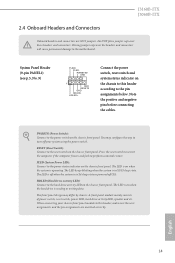
... the chassis front panel. You may differ by chassis. English 14 2.4 Onboard Headers and Connectors J3160B-ITX J3060B-ITX Onboard headers and connectors are matched correctly. The LED is off (S5). PWRBTN (Power Switch): Connect to the motherboard. Do NOT place jumper caps over the headers and connectors will cause permanent damage to the...
... the chassis front panel. You may differ by chassis. English 14 2.4 Onboard Headers and Connectors J3160B-ITX J3060B-ITX Onboard headers and connectors are matched correctly. The LED is off (S5). PWRBTN (Power Switch): Connect to the motherboard. Do NOT place jumper caps over the headers and connectors will cause permanent damage to the...

User Manual
Page 20
...(9-pin USB2_3) (see p.5, No. 5) (9-pin USB4_5) (see p.5, No. 16) GND PRESENCE# MIC_RET OUT_RET 1 OUT2_L J_SENSE OUT2_R MIC2_R MIC2_L This header is one header on this motherboard. Each USB 2.0 header can support two ports. Front Panel Audio Header (9-pin HD_AUDIO1) (see p.5, No. 6) USB_PWR PP+ GND DUMMY 1 GND P+ PUSB_PWR Besides two USB 2.0 ...IntA_P_DGND IntA_P_SSTX+ IntA_P_SSTXGND IntA_P_SSRX+ IntA_P_SSRXVbus 1 Vbus IntA_P_SSRXIntA_P_SSRX+ GND IntA_P_SSTXIntA_P_SSTX+ GND IntA_P_DIntA_P_D+ ID Besides two USB 3.0 ports on the I /O panel, there are two headers on this motherboard.
...(9-pin USB2_3) (see p.5, No. 5) (9-pin USB4_5) (see p.5, No. 16) GND PRESENCE# MIC_RET OUT_RET 1 OUT2_L J_SENSE OUT2_R MIC2_R MIC2_L This header is one header on this motherboard. Each USB 2.0 header can support two ports. Front Panel Audio Header (9-pin HD_AUDIO1) (see p.5, No. 6) USB_PWR PP+ GND DUMMY 1 GND P+ PUSB_PWR Besides two USB 2.0 ...IntA_P_DGND IntA_P_SSTX+ IntA_P_SSTXGND IntA_P_SSRX+ IntA_P_SSRXVbus 1 Vbus IntA_P_SSRXIntA_P_SSRX+ GND IntA_P_SSTXIntA_P_SSTX+ GND IntA_P_DIntA_P_D+ ID Besides two USB 3.0 ports on the I /O panel, there are two headers on this motherboard.
User Manual
Page 21
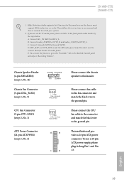
... Ground (GND). D. English 16 Connect Ground (GND) to OUT2_L. To activate the front mic, go to connect them for the HD audio panel only. This motherboard provides a 24-pin ATX power connector. To use an AC'97 audio panel, please install it along Pin 1 and Pin 13. You don't need to... black wire to function correctly. High Definition Audio supports Jack Sensing, but the panel wire on the chassis must support HDA to the ground pin. C. J3160B-ITX J3060B-ITX 1.
... Ground (GND). D. English 16 Connect Ground (GND) to OUT2_L. To activate the front mic, go to connect them for the HD audio panel only. This motherboard provides a 24-pin ATX power connector. To use an AC'97 audio panel, please install it along Pin 1 and Pin 13. You don't need to... black wire to function correctly. High Definition Audio supports Jack Sensing, but the panel wire on the chassis must support HDA to the ground pin. C. J3160B-ITX J3060B-ITX 1.

User Manual
Page 22
... Port Header (9-pin COM2) (see p.5, No. 12) 1 PCICLK FRAME PCIRST# LAD3 +3V LAD0 +3VSB GND GND SMB_CLK_MAIN SMB_DATA_MAIN LAD2 LAD1 GND S_PWRDWN# SERIRQ# GND This motherboard supports CASE OPEN detection feature that detects if the chassis cove has been removed. A TPM system also helps enhance network security, protects digital identities, and...
... Port Header (9-pin COM2) (see p.5, No. 12) 1 PCICLK FRAME PCIRST# LAD3 +3V LAD0 +3VSB GND GND SMB_CLK_MAIN SMB_DATA_MAIN LAD2 LAD1 GND S_PWRDWN# SERIRQ# GND This motherboard supports CASE OPEN detection feature that detects if the chassis cove has been removed. A TPM system also helps enhance network security, protects digital identities, and...
User Manual
Page 23
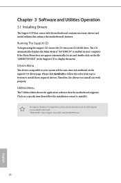
..., locate and double click on the support CD driver page. Utilities Menu The Utilities Menu shows the application software that enhance the motherboard's features. Drivers Menu The drivers compatible to your system will be auto-detected and listed on the file "ASRSETUP.EXE" in ... to install it. Chapter 3 Software and Utilities Operation 3.1 Installing Drivers The Support CD that comes with the motherboard contains necessary drivers and useful utilities that the motherboard supports. "KB2720599": http://support.microsoft.com/kb/2720599/en-us 18 English Running The Support CD To begin ...
..., locate and double click on the support CD driver page. Utilities Menu The Utilities Menu shows the application software that enhance the motherboard's features. Drivers Menu The drivers compatible to your system will be auto-detected and listed on the file "ASRSETUP.EXE" in ... to install it. Chapter 3 Software and Utilities Operation 3.1 Installing Drivers The Support CD that comes with the motherboard contains necessary drivers and useful utilities that the motherboard supports. "KB2720599": http://support.microsoft.com/kb/2720599/en-us 18 English Running The Support CD To begin ...
User Manual
Page 24
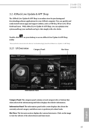
...such as USB Key, XFast LAN, XFast RAM and more . 19 English J3160B-ITX J3060B-ITX 3.2 ASRock Live Update & APP Shop The ASRock Live Update & APP Shop is an online store for purchasing and downloading software applications for your ASRock computer. Hot News: The hot news section displays the various latest news. ...You can optimize your system and keep your desktop to access ASRock Live Update & APP Shop *You need to be connected to the Internet to visit the website of the selected news and know more . Click on your motherboard up to perform job-related tasks.
...such as USB Key, XFast LAN, XFast RAM and more . 19 English J3160B-ITX J3060B-ITX 3.2 ASRock Live Update & APP Shop The ASRock Live Update & APP Shop is an online store for purchasing and downloading software applications for your ASRock computer. Hot News: The hot news section displays the various latest news. ...You can optimize your system and keep your desktop to access ASRock Live Update & APP Shop *You need to be connected to the Internet to visit the website of the selected news and know more . Click on your motherboard up to perform job-related tasks.
User Manual
Page 30
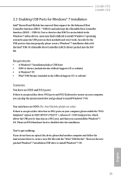
...• A Windows® 7 installation disk or USB drive • USB 3.0 drivers (included in the ASRock Support CD or website) • A Windows® PC • Win7 USB Patcher (included in the ASRock Support CD or website) Scenarios You have an optical disc drive, please find it difficult to install Windows... the USB ports on your computer, you can skip the instructions below and go ahead to disabled after the installation. J3160B-ITX J3060B-ITX 3.3 Enabling USB Ports for Windows® 7 Installation Intel® Braswell and Skylake has removed their motherboard won't work.
...• A Windows® 7 installation disk or USB drive • USB 3.0 drivers (included in the ASRock Support CD or website) • A Windows® PC • Win7 USB Patcher (included in the ASRock Support CD or website) Scenarios You have an optical disc drive, please find it difficult to install Windows... the USB ports on your computer, you can skip the instructions below and go ahead to disabled after the installation. J3160B-ITX J3060B-ITX 3.3 Enabling USB Ports for Windows® 7 Installation Intel® Braswell and Skylake has removed their motherboard won't work.
User Manual
Page 49
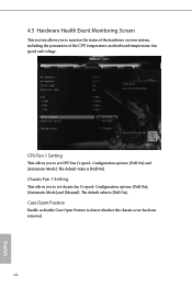
... [Full On]. CPU Fan 1 Setting This allows you to monitor the status of the hardware on your system, including the parameters of the CPU temperature, motherboard temperature, fan speed and voltage. Configuration options: [Full On] and [Automatic Mode]. 4.5 Hardware Health Event Monitoring Screen This section allows you to set chassis fan...
... [Full On]. CPU Fan 1 Setting This allows you to monitor the status of the hardware on your system, including the parameters of the CPU temperature, motherboard temperature, fan speed and voltage. Configuration options: [Full On] and [Automatic Mode]. 4.5 Hardware Health Event Monitoring Screen This section allows you to set chassis fan...

