User Manual
Page 5
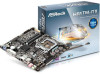
...-step installation guides. In case any modifications of this manual, Chapter 1 and 2 contains the introduction of this documentation will be subject to this motherboard, please visit our website for specific information about the model you for purchasing ASRock H81TM-ITX motherboard, a reliable motherboard produced under ASRock's consistently stringent quality control. You may find the latest...
...-step installation guides. In case any modifications of this manual, Chapter 1 and 2 contains the introduction of this documentation will be subject to this motherboard, please visit our website for specific information about the model you for purchasing ASRock H81TM-ITX motherboard, a reliable motherboard produced under ASRock's consistently stringent quality control. You may find the latest...
User Manual
Page 26
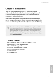
Please connect a SATA power cable. B. C. D. To activate the front mic, go to the "FrontMic" Tab in our manual and chassis manual to install your system. 2. Each USB 2.0 header can support two ports. 1 GND P+ PUSB_PWR Front Panel Audio Header GN D (9-pin HD_AUDIO1) (see p.9, No. 7) These two SATA3 ...
Please connect a SATA power cable. B. C. D. To activate the front mic, go to the "FrontMic" Tab in our manual and chassis manual to install your system. 2. Each USB 2.0 header can support two ports. 1 GND P+ PUSB_PWR Front Panel Audio Header GN D (9-pin HD_AUDIO1) (see p.9, No. 7) These two SATA3 ...
User Manual
Page 58
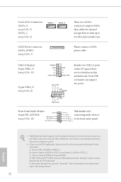
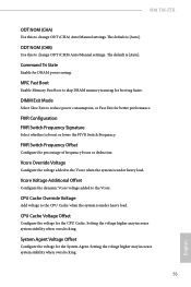
...Configure between module write to write delay. IO-L (CHB) Configure IO latency for channel A. tWRRDDD Use this to change DRAM tRRSR Auto/Manual settings. ODT WR (CHA) Configure the memory on die termination resistors' WR for channel A. tWRWRDR Configure between module write to write ...delay from different DIMMs. tWRWR Configure between module write to write delay from different ranks. tRDRDDD Use this to change DRAM tRWSR Auto/Manual settings. RTL (CHB) Configure round trip latency for channel A. IO-L (CHA) Configure IO latency for channel B. ODT WR (CHB...
...Configure between module write to write delay. IO-L (CHB) Configure IO latency for channel A. tWRRDDD Use this to change DRAM tRRSR Auto/Manual settings. ODT WR (CHA) Configure the memory on die termination resistors' WR for channel A. tWRWRDR Configure between module write to write ...delay from different DIMMs. tWRWR Configure between module write to write delay from different ranks. tRDRDDD Use this to change DRAM tRWSR Auto/Manual settings. RTL (CHB) Configure round trip latency for channel A. IO-L (CHA) Configure IO latency for channel B. ODT WR (CHB...
User Manual
Page 59
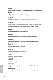
.... System Agent Voltage Offset Configure the voltage for the System Agent. ODT NOM (CHB) Use this to change ODT (CHB) Auto/Manual settings. FIVR Switch Frequency Offset Configure the percentage of frequency boost or deduction. The default is under heavy load. H81TM-ITX ODT NOM (CHA) Use this to change ODT (CHA) Auto...
.... System Agent Voltage Offset Configure the voltage for the System Agent. ODT NOM (CHB) Use this to change ODT (CHB) Auto/Manual settings. FIVR Switch Frequency Offset Configure the percentage of frequency boost or deduction. The default is under heavy load. H81TM-ITX ODT NOM (CHA) Use this to change ODT (CHA) Auto...
Quick Installation Guide
Page 23
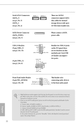
... OUT2_R MIC2_R to 6.0 Gb/s data transfer rate. D. Connect Ground (GND) to OUT2_L. To activate the front mic, go to the "FrontMic" Tab in our manual and chassis manual to MIC2_L. USB 2.0 Headers (9-pin USB2_3) (see p.1, No. 15) (9-pin USB4_5) (see p.1, No. 6) DUMMY GND P+ P- Connect Audio_R (RIN) to OUT2_R and Audio_L (LIN) to...
... OUT2_R MIC2_R to 6.0 Gb/s data transfer rate. D. Connect Ground (GND) to OUT2_L. To activate the front mic, go to the "FrontMic" Tab in our manual and chassis manual to MIC2_L. USB 2.0 Headers (9-pin USB2_3) (see p.1, No. 15) (9-pin USB4_5) (see p.1, No. 6) DUMMY GND P+ P- Connect Audio_R (RIN) to OUT2_R and Audio_L (LIN) to...
