Quick Installation Guide
Page 3
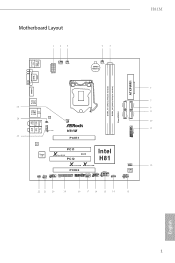
Motherboard Layout H81M USB 2.0 T: USB0 B: USB1 PS2 Keyboard HDMI1 SATA_4 SATA_0 CPU_FAN1 CPU_FAN2 ATX12V1 PWR_FAN1 CMOS Battery DVI1 VGA1 ATXPWR1 DDR3_A1 (64 bit, 240-pin module) DDR3_A2 (64 bit, 240-pin module) USB 2.0 T: USB4 B: USB5 USB 3.0 T: USB0 B: USB1 Top: RJ-45 LAN Top: 1 SPDIF1_OUT1 CHA_FAN2 Central/Bass LINE IN Center: REAR SPK FRONT Top: Center: HD_AUDIO1 1 H81M PCIE1 Audio CODEC Super I/O CI1 1 IR1 1 PCI1 X Fast RAM PCI2 RoHS...
Motherboard Layout H81M USB 2.0 T: USB0 B: USB1 PS2 Keyboard HDMI1 SATA_4 SATA_0 CPU_FAN1 CPU_FAN2 ATX12V1 PWR_FAN1 CMOS Battery DVI1 VGA1 ATXPWR1 DDR3_A1 (64 bit, 240-pin module) DDR3_A2 (64 bit, 240-pin module) USB 2.0 T: USB4 B: USB5 USB 3.0 T: USB0 B: USB1 Top: RJ-45 LAN Top: 1 SPDIF1_OUT1 CHA_FAN2 Central/Bass LINE IN Center: REAR SPK FRONT Top: Center: HD_AUDIO1 1 H81M PCIE1 Audio CODEC Super I/O CI1 1 IR1 1 PCI1 X Fast RAM PCI2 RoHS...
Quick Installation Guide
Page 4
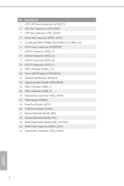
...ATX 12V Power Connector (ATX12V1) 2 CPU Fan Connector (CPU_FAN1) 3 CPU Fan Connector (CPU_FAN2) 4 Power Fan Connector (PWR_FAN1) 5 2 x 240-pin DDR3 DIMM Slots (DDR3_A1, DDR3_A2) 6 ATX Power Connector (ATXPWR1) 7 SATA2 Connector (SATA_5) 8 SATA2 Connector (SATA_4) 9 SATA3 Connector (SATA_0) 10 SATA3 Connector (SATA_1) 11 USB 3.0 Header (USB3_2_3) 12 Clear CMOS Jumper (CLRCMOS1) 13 System Panel Header (PANEL1) 14 Chassis Speaker Header (SPEAKER1) 15 USB 2.0 Header (USB6_7) 16 USB 2.0 Header (USB8_9) 17 Chassis Fan Connector (CHA_FAN1) 17 TPM Header (TPMS1) 19 Print Port Header (LPT1) 20 COM Port...
...ATX 12V Power Connector (ATX12V1) 2 CPU Fan Connector (CPU_FAN1) 3 CPU Fan Connector (CPU_FAN2) 4 Power Fan Connector (PWR_FAN1) 5 2 x 240-pin DDR3 DIMM Slots (DDR3_A1, DDR3_A2) 6 ATX Power Connector (ATXPWR1) 7 SATA2 Connector (SATA_5) 8 SATA2 Connector (SATA_4) 9 SATA3 Connector (SATA_0) 10 SATA3 Connector (SATA_1) 11 USB 3.0 Header (USB3_2_3) 12 Clear CMOS Jumper (CLRCMOS1) 13 System Panel Header (PANEL1) 14 Chassis Speaker Header (SPEAKER1) 15 USB 2.0 Header (USB6_7) 16 USB 2.0 Header (USB8_9) 17 Chassis Fan Connector (CHA_FAN1) 17 TPM Header (TPMS1) 19 Print Port Header (LPT1) 20 COM Port...
Quick Installation Guide
Page 7
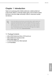
..., the updated version will be available on ASRock's website as well. H81M Chapter 1 Introduction Thank you are using. Because the motherboard specifications and the BIOS software might be updated, the content of this documentation will be subject to quality and endurance. ASRock website http://www.asrock.com. 1.1 Package Contents • ASRock H81M Motherboard (Micro ATX Form Factor) • ASRock H81M Quick Installation Guide • ASRock H81M Support CD • 2 x Serial ATA (SATA) Data Cables (Optional) • 1 x I/O Panel Shield...
..., the updated version will be available on ASRock's website as well. H81M Chapter 1 Introduction Thank you are using. Because the motherboard specifications and the BIOS software might be updated, the content of this documentation will be subject to quality and endurance. ASRock website http://www.asrock.com. 1.1 Package Contents • ASRock H81M Motherboard (Micro ATX Form Factor) • ASRock H81M Quick Installation Guide • ASRock H81M Support CD • 2 x Serial ATA (SATA) Data Cables (Optional) • 1 x I/O Panel Shield...
Quick Installation Guide
Page 8
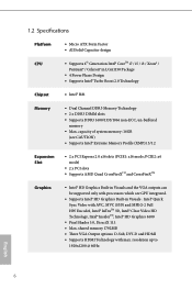
... and the VGA outputs can be supported only with processors which are GPU integrated. • Supports Intel® HD Graphics Built-in LGA1150 Package • 4 Power Phase Design • Supports Intel® Turbo Boost 2.0 Technology Chipset • Intel® H81 Memory • Dual Channel DDR3 Memory Technology • 2 x DDR3 DIMM slots • Supports DDR3 1600/1333/1066 non-ECC, un-buffered memory • Max. 1.2 Specifications Platform CPU • Micro ATX Form...
... and the VGA outputs can be supported only with processors which are GPU integrated. • Supports Intel® HD Graphics Built-in LGA1150 Package • 4 Power Phase Design • Supports Intel® Turbo Boost 2.0 Technology Chipset • Intel® H81 Memory • Dual Channel DDR3 Memory Technology • 2 x DDR3 DIMM slots • Supports DDR3 1600/1333/1066 non-ECC, un-buffered memory • Max. 1.2 Specifications Platform CPU • Micro ATX Form...
Quick Installation Guide
Page 9
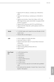
...® Atheros® AR8171 • Supports Qualcomm® Atheros® Security Wake On Internet Technology • Supports Wake-On-LAN • Supports Energy Efficient Ethernet 802.3az • Supports PXE Rear Panel I/O • 1 x PS/2 Keyboard Port • 1 x D-Sub Port • 1 x DVI-D Port • 1 x HDMI Port • 1 x Optical SPDIF Out Port • 4 x USB 2.0 Ports • 2 x USB 3.0 Ports • 1 x RJ-45 LAN Port with LED (ACT/LINK LED and SPEED LED) • HD Audio Jack: Rear Speaker / Central / Bass / Line in...
...® Atheros® AR8171 • Supports Qualcomm® Atheros® Security Wake On Internet Technology • Supports Wake-On-LAN • Supports Energy Efficient Ethernet 802.3az • Supports PXE Rear Panel I/O • 1 x PS/2 Keyboard Port • 1 x D-Sub Port • 1 x DVI-D Port • 1 x HDMI Port • 1 x Optical SPDIF Out Port • 4 x USB 2.0 Ports • 2 x USB 3.0 Ports • 1 x RJ-45 LAN Port with LED (ACT/LINK LED and SPEED LED) • HD Audio Jack: Rear Speaker / Central / Bass / Line in...
Quick Installation Guide
Page 10
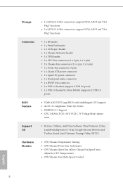
... x 4-pin, 1 x 3-pin) • 1 x Power Fan connector (3-pin) • 1 x 24 pin ATX power connector • 1 x 8 pin 12V power connector • 1 x Front panel audio connector • 1 x SPDIF Out connector • 2 x USB 2.0 headers (support 4 USB 2.0 ports) • 1 x USB 3.0 header by CPU Temperature) • CPU/Chassis Fan Multi-Speed Control English 8 Adjust by Etron EJ168A (supports 2 USB 3.0 ports) • 32Mb AMI UEFI Legal BIOS with Multilingual GUI support • ACPI 1.1 Compliance Wake Up Events • SMBIOS 2.3.1 Support • CPU, DRAM, PCH 1.05V, PCH 1.5V Voltage...
... x 4-pin, 1 x 3-pin) • 1 x Power Fan connector (3-pin) • 1 x 24 pin ATX power connector • 1 x 8 pin 12V power connector • 1 x Front panel audio connector • 1 x SPDIF Out connector • 2 x USB 2.0 headers (support 4 USB 2.0 ports) • 1 x USB 3.0 header by CPU Temperature) • CPU/Chassis Fan Multi-Speed Control English 8 Adjust by Etron EJ168A (supports 2 USB 3.0 ports) • 32Mb AMI UEFI Legal BIOS with Multilingual GUI support • ACPI 1.1 Compliance Wake Up Events • SMBIOS 2.3.1 Support • CPU, DRAM, PCH 1.05V, PCH 1.5V Voltage...
Quick Installation Guide
Page 11
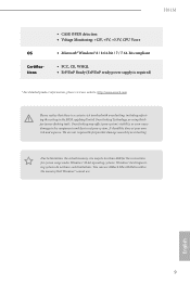
... to utilize the memory that there is a certain risk involved with overclocking, including adjusting the setting in the BIOS, applying Untied Overclocking Technology, or using thirdparty overclocking tools. It should be less than 4GB for the reservation for possible damage caused by overclocking. H81M OS Certifications • CASE OPEN detection • Voltage Monitoring: +12V, +5V, +3.3V, CPU Vcore • Microsoft® Windows® 8 / 8 64-bit / 7 / 7 64-bit compliant...
... to utilize the memory that there is a certain risk involved with overclocking, including adjusting the setting in the BIOS, applying Untied Overclocking Technology, or using thirdparty overclocking tools. It should be less than 4GB for the reservation for possible damage caused by overclocking. H81M OS Certifications • CASE OPEN detection • Voltage Monitoring: +12V, +5V, +3.3V, CPU Vcore • Microsoft® Windows® 8 / 8 64-bit / 7 / 7 64-bit compliant...
Quick Installation Guide
Page 12
...: With the status window, you to the list. Just save the new BIOS file to your PC enters into Standby mode (S1), Suspend to access ASRock Instant Flash. ASRock APP Charger Simply by pressing or during POST to enter the BIOS setup menu to RAM (S3), hibernation mode (S4) or power off (S5). Traffic Shaping: You can boost the performance of the device. This convenient BIOS update tool allows you can...
...: With the status window, you to the list. Just save the new BIOS file to your PC enters into Standby mode (S1), Suspend to access ASRock Instant Flash. ASRock APP Charger Simply by pressing or during POST to enter the BIOS setup menu to RAM (S3), hibernation mode (S4) or power off (S5). Traffic Shaping: You can boost the performance of the device. This convenient BIOS update tool allows you can...
Quick Installation Guide
Page 13
... without entering Windows® OS. ASRock Internet Flash ASRock Internet Flash downloads and updates the latest UEFI firmware version from bypassing OMG, guest accounts without fear of failing. It fully utilizes the memory space that cannot be placed in the root directory of your USB disk. ASRock Crashless BIOS ASRock Crashless BIOS allows users to dehumidify the system after regaining power. Only USB 2.0 ports support this feature. You may prevent motherboard damages due to other users. ASRock...
... without entering Windows® OS. ASRock Internet Flash ASRock Internet Flash downloads and updates the latest UEFI firmware version from bypassing OMG, guest accounts without fear of failing. It fully utilizes the memory space that cannot be placed in the root directory of your USB disk. ASRock Crashless BIOS ASRock Crashless BIOS allows users to dehumidify the system after regaining power. Only USB 2.0 ports support this feature. You may prevent motherboard damages due to other users. ASRock...
Quick Installation Guide
Page 14
... great audio experience from a cold boot. ASRock Good Night LED ASRock Good Night LED technology offers you restart. This motherboard also provides a free 3.5mm audio cable (optional) that ensures users the most convenient computing environment. ASRock USB Key In a world where time is a blend of system configuration tools, cool sound effects and stunning visuals. Why should we even bother memorizing those foot long passwords? The lightning boot up experience. By enabling this...
... great audio experience from a cold boot. ASRock Good Night LED ASRock Good Night LED technology offers you restart. This motherboard also provides a free 3.5mm audio cable (optional) that ensures users the most convenient computing environment. ASRock USB Key In a world where time is a blend of system configuration tools, cool sound effects and stunning visuals. Why should we even bother memorizing those foot long passwords? The lightning boot up experience. By enabling this...
Quick Installation Guide
Page 15
... five different fan speeds using the graph. H81M ASRock Home Cloud This motherboard supports Security Wake On Internet Technology with the onboard Qualcomm® Atheros® LAN, so you can connect with another smartphone, tablet or computer. Configure up to power your PC on or turn it off, monitor and take control of it remotely with your system via an USB storage device, then downloads and installs the other required drivers automatically. 13...
... five different fan speeds using the graph. H81M ASRock Home Cloud This motherboard supports Security Wake On Internet Technology with the onboard Qualcomm® Atheros® LAN, so you can connect with another smartphone, tablet or computer. Configure up to power your PC on or turn it off, monitor and take control of it remotely with your system via an USB storage device, then downloads and installs the other required drivers automatically. 13...
Quick Installation Guide
Page 16
Failure to unplug the power cord before installing or removing the motherboard. Also remember to use a grounded wrist strap or touch a safety grounded object before you and damages to motherboard components. • In order to avoid damage from static electricity to the motherboard's components, NEVER place your chassis to ensure that comes with the components. • When placing screws to...
Failure to unplug the power cord before installing or removing the motherboard. Also remember to use a grounded wrist strap or touch a safety grounded object before you and damages to motherboard components. • In order to avoid damage from static electricity to the motherboard's components, NEVER place your chassis to ensure that comes with the components. • When placing screws to...
Quick Installation Guide
Page 21
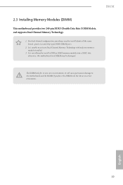
... slots, and supports Dual Channel Memory Technology. 1. For dual channel configuration, you force the DIMM into a DDR3 slot; The DIMM only fits in one memory module installed. 3. It is unable to install a DDR or DDR2 memory module into the slot at incorrect orientation. 19 English It will cause permanent damage to the motherboard and the DIMM if you always need to install identical (the same brand, speed, size and chip-type...
... slots, and supports Dual Channel Memory Technology. 1. For dual channel configuration, you force the DIMM into a DDR3 slot; The DIMM only fits in one memory module installed. 3. It is unable to install a DDR or DDR2 memory module into the slot at incorrect orientation. 19 English It will cause permanent damage to the motherboard and the DIMM if you always need to install identical (the same brand, speed, size and chip-type...
Quick Installation Guide
Page 23
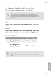
... environment, please connect a chassis fan to install expansion cards that the power supply is switched off or the power cord is unplugged. PCIe slots: PCIE1 (PCIe 2.0 x16 slot) is used for PCI Express x4 lane width graphics cards. PCI slot: The PCI1 and PCI2 slots are 2 PCI slots and 2 PCI Express slots on the motherboard. Please read the documentation of the expansion card and make sure that have 32-bit PCI interface. 2.4 Expansion Slots (PCI and PCI Express Slots) There are used to the motherboard's chassis fan connector (CHA_FAN1 or...
... environment, please connect a chassis fan to install expansion cards that the power supply is switched off or the power cord is unplugged. PCIe slots: PCIE1 (PCIe 2.0 x16 slot) is used for PCI Express x4 lane width graphics cards. PCI slot: The PCI1 and PCI2 slots are 2 PCI slots and 2 PCI Express slots on the motherboard. Please read the documentation of the expansion card and make sure that have 32-bit PCI interface. 2.4 Expansion Slots (PCI and PCI Express Slots) There are used to the motherboard's chassis fan connector (CHA_FAN1 or...
Quick Installation Guide
Page 24
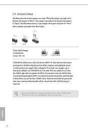
.... Clear CMOS Jumper (CLRCMOS1) (see p.1, No. 12) Default Clear CMOS CLRCMOS1 allows you update the BIOS. However, please do the clear-CMOS action. English 22 The illustration shows a 3-pin jumper whose pin1 and pin2 are setup. Please be noted that the password, date, time, and user default profile will be detected. Please adjust the BIOS option "Clear Status" to default setup, please turn off the computer and unplug the power cord from the power supply.
.... Clear CMOS Jumper (CLRCMOS1) (see p.1, No. 12) Default Clear CMOS CLRCMOS1 allows you update the BIOS. However, please do the clear-CMOS action. English 22 The illustration shows a 3-pin jumper whose pin1 and pin2 are setup. Please be noted that the password, date, time, and user default profile will be detected. Please adjust the BIOS option "Clear Status" to default setup, please turn off the computer and unplug the power cord from the power supply.
Quick Installation Guide
Page 25
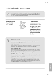
.... Placing jumper caps over these headers and connectors. PWRBTN (Power Switch): Connect to this header according to the hard drive activity LED on the chassis front panel. The LED keeps blinking when the system is in S1/S3 sleep state. A front panel module mainly consists of power switch, reset switch, power LED, hard drive activity LED, speaker and etc. You may differ by chassis. The LED is off your chassis front panel module to the power switch on the chassis front panel. RESET (Reset Switch): Connect to turn off...
.... Placing jumper caps over these headers and connectors. PWRBTN (Power Switch): Connect to this header according to the hard drive activity LED on the chassis front panel. The LED keeps blinking when the system is in S1/S3 sleep state. A front panel module mainly consists of power switch, reset switch, power LED, hard drive activity LED, speaker and etc. You may differ by chassis. The LED is off your chassis front panel module to the power switch on the chassis front panel. RESET (Reset Switch): Connect to turn off...
Quick Installation Guide
Page 26
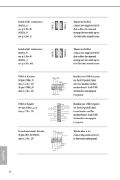
... This header is one header on this motherboard. USB 2.0 Headers (9-pin USB6_7) (see p.1, No. 15) (9-pin USB8_9) (see p.1, No. 16) USB_PWR PP+ GND DUMMY 1 GND P+ PUSB_PWR Besides four USB 2.0 ports on the I /O panel, there is for internal storage devices with up to 6.0 Gb/s data transfer rate. English 24 Serial ATA2 Connectors (SATA_4: see p.1, No. 8) (SATA_5: see p.1, No. 7) SATA_5 SATA_4 These two SATA2 connectors support SATA data cables for internal storage devices with...
... This header is one header on this motherboard. USB 2.0 Headers (9-pin USB6_7) (see p.1, No. 15) (9-pin USB8_9) (see p.1, No. 16) USB_PWR PP+ GND DUMMY 1 GND P+ PUSB_PWR Besides four USB 2.0 ports on the I /O panel, there is for internal storage devices with up to 6.0 Gb/s data transfer rate. English 24 Serial ATA2 Connectors (SATA_4: see p.1, No. 8) (SATA_5: see p.1, No. 7) SATA_5 SATA_4 These two SATA2 connectors support SATA data cables for internal storage devices with...
Quick Installation Guide
Page 27
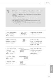
... connect the chassis speaker to this header with a cable. Connect Audio_R (RIN) to OUT2_R and Audio_L (LIN) to MIC2_L. D. Chassis Speaker Header (4-pin SPEAKER1) (see p.1, No. 4) English 25 H81M 1. Connect Mic_IN (MIC) to OUT2_L. You don't need to this header. SPDIF Out Connector (2-pin SPDIF_OUT1) (see p.1, No. 24) 1 GND SPDIFOUT Please connect the SPDIF_OUT connector of a HDMI VGA card to connect them for the HD audio panel only. If you use an AC'97 audio panel, please install...
... connect the chassis speaker to this header with a cable. Connect Audio_R (RIN) to OUT2_R and Audio_L (LIN) to MIC2_L. D. Chassis Speaker Header (4-pin SPEAKER1) (see p.1, No. 4) English 25 H81M 1. Connect Mic_IN (MIC) to OUT2_L. You don't need to this header. SPDIF Out Connector (2-pin SPDIF_OUT1) (see p.1, No. 24) 1 GND SPDIFOUT Please connect the SPDIF_OUT connector of a HDMI VGA card to connect them for the HD audio panel only. If you use an AC'97 audio panel, please install...
Quick Installation Guide
Page 28
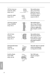
ATX 12V Power Connector (8-pin ATX12V1) (see p.1, No. 6) 12 24 1 13 This motherboard provides a 24-pin ATX power connector. English 26 If you plan to connect a 3-Pin CPU fan, please connect it along Pin 1 and Pin 13. vides an 8-pin ATX 12V power connector. To use a 8 4 4-pin ATX power supply, please plug it to Pin 1-3. This COM1 header supports a serial port module. ATX Power Connector (24-pin ATXPWR1) (see p.1, No. 1) 5 1 This motherboard pro- To use a 20-pin ATX power supply, please plug it along Pin 1 and Pin 5. CPU Fan Connectors (4-pin CPU_FAN1) (...
ATX 12V Power Connector (8-pin ATX12V1) (see p.1, No. 6) 12 24 1 13 This motherboard provides a 24-pin ATX power connector. English 26 If you plan to connect a 3-Pin CPU fan, please connect it along Pin 1 and Pin 13. vides an 8-pin ATX 12V power connector. To use a 8 4 4-pin ATX power supply, please plug it to Pin 1-3. This COM1 header supports a serial port module. ATX Power Connector (24-pin ATXPWR1) (see p.1, No. 1) 5 1 This motherboard pro- To use a 20-pin ATX power supply, please plug it along Pin 1 and Pin 5. CPU Fan Connectors (4-pin CPU_FAN1) (...
Quick Installation Guide
Page 29
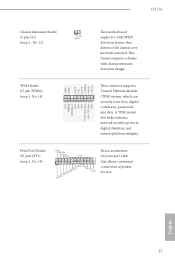
H81M Chassis Intrusion Header (2-pin CI1) (see p.1, No. 22) 1 GND Signal This motherboard supports CASE OPEN detection feature that allows convenient connection of printer devices. TPM Header (17-pin TPMS1) (see p.1, No. 19) AFD# ERROR# PINIT# SLIN# GND 1 SPD7 SPD6 ACK# SPD5 BUSY SPD4 PE SPD3 SLCT SPD2 SPD1 SPD0 STB# This is an interface for print port cable that detects if the chassis cove has...
H81M Chassis Intrusion Header (2-pin CI1) (see p.1, No. 22) 1 GND Signal This motherboard supports CASE OPEN detection feature that allows convenient connection of printer devices. TPM Header (17-pin TPMS1) (see p.1, No. 19) AFD# ERROR# PINIT# SLIN# GND 1 SPD7 SPD6 ACK# SPD5 BUSY SPD4 PE SPD3 SLCT SPD2 SPD1 SPD0 STB# This is an interface for print port cable that detects if the chassis cove has...


