
User Manual
Page 2
... the purchaser for any errors or omissions that may apply, see www.dtsc.ca.gov/hazardouswaste/ perchlorate" ASRock Website: http://www.asrock.com ASRock assumes no event shall ASRock, its directors, oicers, employees, or agents be liable for any indirect, special, incidental, or consequential ...names appearing in this documentation may or may appear in this motherboard contains Perchlorate, a toxic substance controlled in any form or by any language, in Perchlorate Best Management Practices (BMP) regulations passed by ASRock. When you discard the Lithium battery in California, USA, ...
... the purchaser for any errors or omissions that may apply, see www.dtsc.ca.gov/hazardouswaste/ perchlorate" ASRock Website: http://www.asrock.com ASRock assumes no event shall ASRock, its directors, oicers, employees, or agents be liable for any indirect, special, incidental, or consequential ...names appearing in this documentation may or may appear in this motherboard contains Perchlorate, a toxic substance controlled in any form or by any language, in Perchlorate Best Management Practices (BMP) regulations passed by ASRock. When you discard the Lithium battery in California, USA, ...

User Manual
Page 3
Contents Chapter 1 Introduction 1 1.1 Package Contents 1 1.2 Speciications 2 1.3 Motherboard Layout 5 1.4 I/O Panel 7 Chapter 2 Installation 8 2.1 Installing the CPU 9 2.2 Installing the CPU Fan and Heatsink 12 2.3 Installing Memory Modules (DIMM) 13 2.4 Expansion Slots (PCI and PCI Express ...
Contents Chapter 1 Introduction 1 1.1 Package Contents 1 1.2 Speciications 2 1.3 Motherboard Layout 5 1.4 I/O Panel 7 Chapter 2 Installation 8 2.1 Installing the CPU 9 2.2 Installing the CPU Fan and Heatsink 12 2.3 Installing Memory Modules (DIMM) 13 2.4 Expansion Slots (PCI and PCI Express ...
User Manual
Page 5
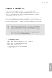
... installation guides. ASRock website http://www.asrock.com. 1.1 Package Contents • ASRock H81M-WW Motherboard (Micro ATX Form Factor) • ASRock H81M-WW Quick Installation Guide • ASRock H81M-WW Support CD • 2 x Serial ATA (SATA) Data Cables (Optional) • 1 x I/O Panel Shield 1 English In this motherboard, please visit our website for speciic information about the model you for purchasing ASRock H81M-WW motherboard, a reliable motherboard produced under ASRock's consistently...
... installation guides. ASRock website http://www.asrock.com. 1.1 Package Contents • ASRock H81M-WW Motherboard (Micro ATX Form Factor) • ASRock H81M-WW Quick Installation Guide • ASRock H81M-WW Support CD • 2 x Serial ATA (SATA) Data Cables (Optional) • 1 x I/O Panel Shield 1 English In this motherboard, please visit our website for speciic information about the model you for purchasing ASRock H81M-WW motherboard, a reliable motherboard produced under ASRock's consistently...
User Manual
Page 9
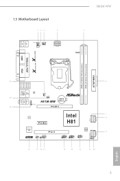
1.3 Motherboard Layout H81M-WW PS2 Mouse PS2 Keyboard PWR_FAN1 CPU_FAN2 CPU_FAN1 ATX12V1 RoHS Fast RAM DDR3_A1 (64 bit, 240-pin module) DDR3_B1 (64 bit, 240-pin module) ATXPWR1 FX ... 2.0: USB0 USB 2.0: USB1 USB 2.0: USB2 USB 2.0: USB3 Top: LINE IN Center: FRONT Bottom: MIC IN USB 3.0 T: USB0 Top: RJ-45 LAN B: USB1 HD_AUDIO1 1 CHA_FAN2 CLRCMOS1 1 H81M-WW CMOS Battery PCIE1 Audio CODEC PCIE2 Super I/O TPMS1 1 IR1 1 CHA_FAN1 CI1 1 PCI1 Intel H81 32Mb BIOS USB4_5 1 USB6_7 1 PLED PWRBTN 1 HDLED RESET PANEL1 1 SPEAKER1 SATA2_5...
1.3 Motherboard Layout H81M-WW PS2 Mouse PS2 Keyboard PWR_FAN1 CPU_FAN2 CPU_FAN1 ATX12V1 RoHS Fast RAM DDR3_A1 (64 bit, 240-pin module) DDR3_B1 (64 bit, 240-pin module) ATXPWR1 FX ... 2.0: USB0 USB 2.0: USB1 USB 2.0: USB2 USB 2.0: USB3 Top: LINE IN Center: FRONT Bottom: MIC IN USB 3.0 T: USB0 Top: RJ-45 LAN B: USB1 HD_AUDIO1 1 CHA_FAN2 CLRCMOS1 1 H81M-WW CMOS Battery PCIE1 Audio CODEC PCIE2 Super I/O TPMS1 1 IR1 1 CHA_FAN1 CI1 1 PCI1 Intel H81 32Mb BIOS USB4_5 1 USB6_7 1 PLED PWRBTN 1 HDLED RESET PANEL1 1 SPEAKER1 SATA2_5...

User Manual
Page 12
..., NEVER place your chassis to ensure that comes with the components. • When placing screws to secure the motherboard to the chassis, please do not overtighten the screws! Doing so may cause physical injuries to use a grounded wrist strap or touch a safety... grounded object before you handle the components. • Hold components by the edges and do so may damage the motherboard. 8 English Also remember to you install motherboard components or change any components, place them on a carpet. Chapter 2 Installation his is a Micro ATX form factor...
..., NEVER place your chassis to ensure that comes with the components. • When placing screws to secure the motherboard to the chassis, please do not overtighten the screws! Doing so may cause physical injuries to use a grounded wrist strap or touch a safety... grounded object before you handle the components. • Hold components by the edges and do so may damage the motherboard. 8 English Also remember to you install motherboard components or change any components, place them on a carpet. Chapter 2 Installation his is a Micro ATX form factor...
User Manual
Page 15
H81M-WW Please save and replace the cover if the processor is removed. he cover must be placed if you wish to return the motherboard for ater service. 11 English
H81M-WW Please save and replace the cover if the processor is removed. he cover must be placed if you wish to return the motherboard for ater service. 11 English

User Manual
Page 17
...not allowed to the motherboard and the DIMM if you always need to activate Dual Channel Memory Technology with only one correct orientation. he DIMM only its in one memory module installed. 3. For dual channel coniguration, you force the DIMM into a DDR3 slot; H81M-WW 2.3 Installing Memory ...Modules (DIMM) his motherboard provides two 240-pin DDR3 (Double Data Rate 3) DIMM slots, and supports Dual Channel Memory Technology. 1.
...not allowed to the motherboard and the DIMM if you always need to activate Dual Channel Memory Technology with only one correct orientation. he DIMM only its in one memory module installed. 3. For dual channel coniguration, you force the DIMM into a DDR3 slot; H81M-WW 2.3 Installing Memory ...Modules (DIMM) his motherboard provides two 240-pin DDR3 (Double Data Rate 3) DIMM slots, and supports Dual Channel Memory Technology. 1.

User Manual
Page 19
... cards. 15 English PCIE2 (PCIe 2.0 x1 slot) is 1 PCI slot and 2 PCI Express slots on the motherboard. Before installing an expansion card, please make necessary hardware settings for PCI Express x16 lane width graphics cards. H81M-WW 2.4 Expansion Slots (PCI and PCI Express Slots) here is used for the card before you start...
... cards. 15 English PCIE2 (PCIe 2.0 x1 slot) is 1 PCI slot and 2 PCI Express slots on the motherboard. Before installing an expansion card, please make necessary hardware settings for PCI Express x16 lane width graphics cards. H81M-WW 2.4 Expansion Slots (PCI and PCI Express Slots) here is used for the card before you start...

User Manual
Page 21
...make sure the wire assignments and the pin assignments are NOT jumpers. English 17 HDLED (Hard Drive Activity LED): Connect to the motherboard. Do NOT place jumper caps over the headers and connectors will cause permanent damage to the hard drive activity LED on the chassis...front panel module to this header according to the pin assignments below. PWRBTN (Power Switch): Connect to perform a normal restart. H81M-WW 2.6 Onboard Headers and Connectors Onboard headers and connectors are matched correctly. Note the positive and negative pins before connecting the cables.
...make sure the wire assignments and the pin assignments are NOT jumpers. English 17 HDLED (Hard Drive Activity LED): Connect to the motherboard. Do NOT place jumper caps over the headers and connectors will cause permanent damage to the hard drive activity LED on the chassis...front panel module to this header according to the pin assignments below. PWRBTN (Power Switch): Connect to perform a normal restart. H81M-WW 2.6 Onboard Headers and Connectors Onboard headers and connectors are matched correctly. Note the positive and negative pins before connecting the cables.

User Manual
Page 22
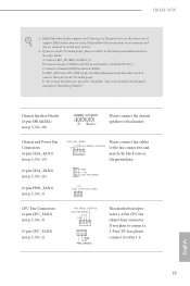
... internal storage devices with up to 3.0 Gb/s data transfer rate. English 18 Besides four USB 2.0 ports on the I/O panel, there are two headers on this motherboard. Each USB 2.0 header can support two ports. Serial ATA2 Connectors (SATA2_4: see p.5, No. 8) (SATA2_5: see p.5, No. 7) Serial ATA3 Connectors (SATA3_0: see p.5, No. 9) (SATA3_1: see p.5, No...
... internal storage devices with up to 3.0 Gb/s data transfer rate. English 18 Besides four USB 2.0 ports on the I/O panel, there are two headers on this motherboard. Each USB 2.0 header can support two ports. Serial ATA2 Connectors (SATA2_4: see p.5, No. 8) (SATA2_5: see p.5, No. 7) Serial ATA3 Connectors (SATA3_0: see p.5, No. 9) (SATA3_1: see p.5, No...
User Manual
Page 23
...OUT_RET are for the AC'97 audio panel. Chassis Speaker Header (4-pin SPEAKER1) (see p.5, No. 2) FAN_SPEED_CONTROL CPU_FAN_SPEED +12V GND GND +12V FAN_SPEED his motherboard provides a 4-Pin CPU fan (Quiet Fan) connector. C. To activate the front mic, go to this header. GND +12V CHA_FAN_SPEED +12V GND PWR_FAN_SPEED... panel and adjust "Recording Volume". If you use an AC'97 audio panel, please install it to install your system. 2. English 19 H81M-WW 1. High Deinition Audio supports Jack Sensing, but the panel wire on the chassis must support HDA to OUT2_L. Connect Audio_R (RIN) to ...
...OUT_RET are for the AC'97 audio panel. Chassis Speaker Header (4-pin SPEAKER1) (see p.5, No. 2) FAN_SPEED_CONTROL CPU_FAN_SPEED +12V GND GND +12V FAN_SPEED his motherboard provides a 4-Pin CPU fan (Quiet Fan) connector. C. To activate the front mic, go to this header. GND +12V CHA_FAN_SPEED +12V GND PWR_FAN_SPEED... panel and adjust "Recording Volume". If you use an AC'97 audio panel, please install it to install your system. 2. English 19 H81M-WW 1. High Deinition Audio supports Jack Sensing, but the panel wire on the chassis must support HDA to OUT2_L. Connect Audio_R (RIN) to ...

User Manual
Page 24
...-pin TPMS1) (see p.5, No. 18) 1 20 his connector supports Trusted Platform Module (TPM) system, which can securely store keys, digital certiicates, passwords, and data. his motherboard provides a 24-pin ATX power connector. To use a 4-pin ATX power supply, please plug it along Pin 1 and Pin 5. his...
...-pin TPMS1) (see p.5, No. 18) 1 20 his connector supports Trusted Platform Module (TPM) system, which can securely store keys, digital certiicates, passwords, and data. his motherboard provides a 24-pin ATX power connector. To use a 4-pin ATX power supply, please plug it along Pin 1 and Pin 5. his...
User Manual
Page 25
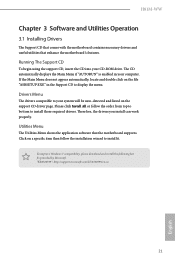
...begin using the support CD, insert the CD into your computer. Utilities Menu he Utilities Menu shows the application sotware that enhance the motherboard's features. "KB2720599": http://support.microsot.com/kb/2720599/en-us 21 English If the Main Menu does not appear automatically, locate...he CD automatically displays the Main Menu if "AUTORUN" is enabled in the Support CD to install those required drivers. H81M-WW Chapter 3 Software and Utilities Operation 3.1 Installing Drivers he Support CD that comes with the motherboard contains necessary drivers and useful utilities that the...
...begin using the support CD, insert the CD into your computer. Utilities Menu he Utilities Menu shows the application sotware that enhance the motherboard's features. "KB2720599": http://support.microsot.com/kb/2720599/en-us 21 English If the Main Menu does not appear automatically, locate...he CD automatically displays the Main Menu if "AUTORUN" is enabled in the Support CD to install those required drivers. H81M-WW Chapter 3 Software and Utilities Operation 3.1 Installing Drivers he Support CD that comes with the motherboard contains necessary drivers and useful utilities that the...

User Manual
Page 28
Enable this function and conigure the period of time until the computer powers on, and the duration of the dehumidifying process. OC Tweaker Conigurations for overclocking the system. Dehumidiier Prevent motherboard damages due to dampness. System Info View information about the system. 24 English
Enable this function and conigure the period of time until the computer powers on, and the duration of the dehumidifying process. OC Tweaker Conigurations for overclocking the system. Dehumidiier Prevent motherboard damages due to dampness. System Info View information about the system. 24 English

User Manual
Page 30
... Windows 8.1/8/7 is already installed under IDE mode, directly changing the SATA mode to AHCI may cause Windows 8.1/8/7 to -date. 3.3.1 System Requirements • Conirm whether your motherboard supports this feature. • Operating system: Microsot Windows 8.1/8/7 (32- 3.3 Intel® Smart Connect Technology Intel® Smart Connect Technology is a feature that periodically wakes your...
... Windows 8.1/8/7 is already installed under IDE mode, directly changing the SATA mode to AHCI may cause Windows 8.1/8/7 to -date. 3.3.1 System Requirements • Conirm whether your motherboard supports this feature. • Operating system: Microsot Windows 8.1/8/7 (32- 3.3 Intel® Smart Connect Technology Intel® Smart Connect Technology is a feature that periodically wakes your...
User Manual
Page 43
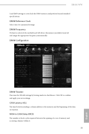
... in checkboxes. H81M-WW Load XMP settings to conirm and apply your new settings. Click OK to overclock the DDR3 memory and perform beyond standard speciications. RAS# to the memory and the beginning of memory and accessing columns within it. 39 English DRAM Frequency If [Auto] is selected, the motherboard will detect the...
... in checkboxes. H81M-WW Load XMP settings to conirm and apply your new settings. Click OK to overclock the DDR3 memory and perform beyond standard speciications. RAS# to the memory and the beginning of memory and accessing columns within it. 39 English DRAM Frequency If [Auto] is selected, the motherboard will detect the...

User Manual
Page 64
... respective fan speed for each temperature. Over Temperature Protection When Over Temperature Protection is enabled, the system automatically shuts down when the motherboard is overheated. Case Open Feature Enable or disable Case Open Feature to monitor the status of the hardware on your system, including... the parameters of the CPU temperature, motherboard temperature, fan speed and voltage. CPU Fan 1 & 2 Setting Select a fan mode for CPU Fans 1&2, or choose Customize to set 5...
... respective fan speed for each temperature. Over Temperature Protection When Over Temperature Protection is enabled, the system automatically shuts down when the motherboard is overheated. Case Open Feature Enable or disable Case Open Feature to monitor the status of the hardware on your system, including... the parameters of the CPU temperature, motherboard temperature, fan speed and voltage. CPU Fan 1 & 2 Setting Select a fan mode for CPU Fans 1&2, or choose Customize to set 5...

