
User Manual
Page 3
... 2 1.3 Motherboard Layout 5 1.4 I/O Panel 7 Chapter 2 Installation 8 2.1 Installing the CPU 9 2.2 Installing the CPU Fan and Heatsink 12 2.3 Installing Memory Modules (DIMM) 13 2.4 Expansion Slots (PCI and PCI Express Slots) 15 2.5 Jumpers Setup 16 2.6 Onboard Headers and Connectors 17 Chapter 3 Software and Utilities Operation 21 3.1 Installing Drivers 21 3.2 A-Tuning 22 3.3 Intel® Smart Connect Technology 26 3.4 Start8 31 Chapter 4 UEFI SETUP UTILITY 34 4.1 Introduction 34 4.1.1 UEFI Menu Bar 34 4.1.2 Navigation Keys 35 4.2 Main Screen 36
... 2 1.3 Motherboard Layout 5 1.4 I/O Panel 7 Chapter 2 Installation 8 2.1 Installing the CPU 9 2.2 Installing the CPU Fan and Heatsink 12 2.3 Installing Memory Modules (DIMM) 13 2.4 Expansion Slots (PCI and PCI Express Slots) 15 2.5 Jumpers Setup 16 2.6 Onboard Headers and Connectors 17 Chapter 3 Software and Utilities Operation 21 3.1 Installing Drivers 21 3.2 A-Tuning 22 3.3 Intel® Smart Connect Technology 26 3.4 Start8 31 Chapter 4 UEFI SETUP UTILITY 34 4.1 Introduction 34 4.1.1 UEFI Menu Bar 34 4.1.2 Navigation Keys 35 4.2 Main Screen 36
User Manual
Page 5
... latest VGA cards and CPU support list on ASRock's website without notice. If you require technical support related to quality and endurance. Chapter 4 contains the coniguration guide of the sotware and utilities. ASRock website http://www.asrock.com. 1.1 Package Contents • ASRock H81M-WW Motherboard (Micro ATX Form Factor) • ASRock H81M-WW Quick Installation Guide • ASRock H81M-WW Support CD • 2 x Serial ATA (SATA) Data Cables (Optional) • 1 x I/O Panel Shield 1 English Chapter 3 contains the operation guide of the BIOS setup. In case...
... latest VGA cards and CPU support list on ASRock's website without notice. If you require technical support related to quality and endurance. Chapter 4 contains the coniguration guide of the sotware and utilities. ASRock website http://www.asrock.com. 1.1 Package Contents • ASRock H81M-WW Motherboard (Micro ATX Form Factor) • ASRock H81M-WW Quick Installation Guide • ASRock H81M-WW Support CD • 2 x Serial ATA (SATA) Data Cables (Optional) • 1 x I/O Panel Shield 1 English Chapter 3 contains the operation guide of the BIOS setup. In case...
User Manual
Page 7
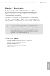
... x USB 3.0 Ports • 1 x RJ-45 LAN Port with LED (ACT/LINK LED and SPEED LED) • HD Audio Jack: Line in / Front Speaker / Microphone • 2 x SATA3 6.0 Gb/s connectors, support NCQ, AHCI and "Hot Plug" functions • 2 x SATA2 3.0 Gb/s connectors, support NCQ, AHCI and "Hot Plug" functions • 1 x IR header • 1 x Chassis Intrusion header • 1 x TPM header • 2 x CPU Fan connectors (1 x 4-pin, 1 x 3-pin) • 2 x Chassis Fan connectors (1 x 4-pin, 1 x 3-pin) • 1 x Power Fan connector (3-pin) • 1 x 24 pin ATX power connector • 1 x 8 pin 12V...
... x USB 3.0 Ports • 1 x RJ-45 LAN Port with LED (ACT/LINK LED and SPEED LED) • HD Audio Jack: Line in / Front Speaker / Microphone • 2 x SATA3 6.0 Gb/s connectors, support NCQ, AHCI and "Hot Plug" functions • 2 x SATA2 3.0 Gb/s connectors, support NCQ, AHCI and "Hot Plug" functions • 1 x IR header • 1 x Chassis Intrusion header • 1 x TPM header • 2 x CPU Fan connectors (1 x 4-pin, 1 x 3-pin) • 2 x Chassis Fan connectors (1 x 4-pin, 1 x 3-pin) • 1 x Power Fan connector (3-pin) • 1 x 24 pin ATX power connector • 1 x 8 pin 12V...

User Manual
Page 8
... power supply is a certain risk involved with Multilingual GUI support • ACPI 1.1 Compliance Wake Up Events • SMBIOS 2.3.1 Support • CPU, DRAM, PCH 1.05V, PCH 1.5V Voltage Multi-adjust- Adjust by overclocking. ment • CPU/Chassis Temperature Sensing • CPU/Chassis/Power Fan Tachometer • CPU/Chassis Quiet Fan (Allow Chassis Fan Speed Auto- BIOS Feature Hardware Monitor OS Certiications • 32Mb AMI UEFI Legal BIOS with overclocking, including adjusting the setting in the BIOS, applying Untied Overclocking Technology, or using thirdparty overclocking...
... power supply is a certain risk involved with Multilingual GUI support • ACPI 1.1 Compliance Wake Up Events • SMBIOS 2.3.1 Support • CPU, DRAM, PCH 1.05V, PCH 1.5V Voltage Multi-adjust- Adjust by overclocking. ment • CPU/Chassis Temperature Sensing • CPU/Chassis/Power Fan Tachometer • CPU/Chassis Quiet Fan (Allow Chassis Fan Speed Auto- BIOS Feature Hardware Monitor OS Certiications • 32Mb AMI UEFI Legal BIOS with overclocking, including adjusting the setting in the BIOS, applying Untied Overclocking Technology, or using thirdparty overclocking...

User Manual
Page 10
... 2 CPU Fan Connector (CPU_FAN2) 3 CPU Fan Connector (CPU_FAN1) 4 ATX 12V Power Connector (ATX12V1) 5 2 x 240-pin DDR3 DIMM Slots (DDR3_A1, DDR3_B1) 6 ATX Power Connector (ATXPWR1) 7 SATA2 Connector (SATA2_5) 8 SATA2 Connector (SATA2_4) 9 SATA3 Connector (SATA3_0) 10 Chassis Speaker Header (SPEAKER1) 11 SATA3 Connector (SATA3_1) 12 System Panel Header (PANEL1) 13 USB 2.0 Header (USB6_7) 14 USB 2.0 Header (USB4_5) 15 Chassis Fan Connector (CHA_FAN1) 16 Chassis Intrusion Header (CI1) 17 Infrared Module Header (IR1) 18 TPM Header (TPMS1) 19 Front Panel Audio Header (HD_AUDIO1) 20 Clear CMOS Jumper...
... 2 CPU Fan Connector (CPU_FAN2) 3 CPU Fan Connector (CPU_FAN1) 4 ATX 12V Power Connector (ATX12V1) 5 2 x 240-pin DDR3 DIMM Slots (DDR3_A1, DDR3_B1) 6 ATX Power Connector (ATXPWR1) 7 SATA2 Connector (SATA2_5) 8 SATA2 Connector (SATA2_4) 9 SATA3 Connector (SATA3_0) 10 Chassis Speaker Header (SPEAKER1) 11 SATA3 Connector (SATA3_1) 12 System Panel Header (PANEL1) 13 USB 2.0 Header (USB6_7) 14 USB 2.0 Header (USB4_5) 15 Chassis Fan Connector (CHA_FAN1) 16 Chassis Intrusion Header (CI1) 17 Infrared Module Header (IR1) 18 TPM Header (TPMS1) 19 Front Panel Audio Header (HD_AUDIO1) 20 Clear CMOS Jumper...

User Manual
Page 12
...motherboard its into it. Failure to unplug the power cord before you install motherboard components or change any components, place them on a carpet. Doing so may cause physical injuries to you uninstall any motherboard settings. • Make sure to do so may damage the motherboard...electricity to the motherboard's components, NEVER place your chassis to use a grounded wrist strap or touch a safety grounded object before installing or removing the motherboard. Chapter 2 Installation his is a Micro ATX form factor motherboard. Before you install the motherboard, study the ...
...motherboard its into it. Failure to unplug the power cord before you install motherboard components or change any components, place them on a carpet. Doing so may cause physical injuries to you uninstall any motherboard settings. • Make sure to do so may damage the motherboard...electricity to the motherboard's components, NEVER place your chassis to use a grounded wrist strap or touch a safety grounded object before installing or removing the motherboard. Chapter 2 Installation his is a Micro ATX form factor motherboard. Before you install the motherboard, study the ...

User Manual
Page 19
... install expansion cards that have 32-bit PCI interface. Please read the documentation of the expansion card and make sure that the power supply is switched of or the power cord is used for the card before you start the installation. Before installing an expansion card, please make necessary hardware settings for PCI Express x16 lane width graphics cards. PCI slot: he PCI1 slot is unplugged. H81M-WW 2.4 Expansion Slots (PCI and PCI Express Slots) here is 1 PCI slot and 2 PCI Express slots on the motherboard...
... install expansion cards that have 32-bit PCI interface. Please read the documentation of the expansion card and make sure that the power supply is switched of or the power cord is used for the card before you start the installation. Before installing an expansion card, please make necessary hardware settings for PCI Express x16 lane width graphics cards. PCI slot: he PCI1 slot is unplugged. H81M-WW 2.4 Expansion Slots (PCI and PCI Express Slots) here is 1 PCI slot and 2 PCI Express slots on the motherboard...

User Manual
Page 20
... "Short". Ater waiting for 15 seconds, use a jumper cap to clear the record of the computer and unplug the power cord from the power supply. Please be noted that the password, date, time, and user default proile will be detected. If you need to default setup, please turn of previous chassis intrusion status. To clear and reset the system parameters to clear the CMOS when you just inish updating...
... "Short". Ater waiting for 15 seconds, use a jumper cap to clear the record of the computer and unplug the power cord from the power supply. Please be noted that the password, date, time, and user default proile will be detected. If you need to default setup, please turn of previous chassis intrusion status. To clear and reset the system parameters to clear the CMOS when you just inish updating...

User Manual
Page 21
... motherboard. he LED is reading or writing data. A front panel module mainly consists of your chassis front panel module to this header according to the power switch on the chassis front panel. H81M-WW 2.6 Onboard Headers and Connectors Onboard headers and connectors are matched correctly. PWRBTN (Power Switch): Connect to the pin assignments below. Placing jumper caps over these headers and connectors. Note the positive and negative pins before connecting the cables. HDLED (Hard Drive Activity LED): Connect to this header, make sure the wire...
... motherboard. he LED is reading or writing data. A front panel module mainly consists of your chassis front panel module to this header according to the power switch on the chassis front panel. H81M-WW 2.6 Onboard Headers and Connectors Onboard headers and connectors are matched correctly. PWRBTN (Power Switch): Connect to the pin assignments below. Placing jumper caps over these headers and connectors. Note the positive and negative pins before connecting the cables. HDLED (Hard Drive Activity LED): Connect to this header, make sure the wire...
User Manual
Page 23
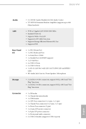
... connect the chassis speaker to MIC2_L. Connect Mic_IN (MIC) to this header. To activate the front mic, go to the ground pin. Chassis and Power Fan Connectors (4-pin CHA_FAN1) (see p.5, No. 15) (3-pin CHA_FAN2) (see p.5, No. 21) (3-pin PWR_FAN1) (see p.5, No. 2) FAN_SPEED_CONTROL CPU_FAN_SPEED +12V GND GND +12V FAN_SPEED his motherboard provides a 4-Pin CPU fan (Quiet Fan) connector. High Deinition Audio supports Jack Sensing, but the panel wire on the chassis must support HDA to function correctly. H81M-WW...
... connect the chassis speaker to MIC2_L. Connect Mic_IN (MIC) to this header. To activate the front mic, go to the ground pin. Chassis and Power Fan Connectors (4-pin CHA_FAN1) (see p.5, No. 15) (3-pin CHA_FAN2) (see p.5, No. 21) (3-pin PWR_FAN1) (see p.5, No. 2) FAN_SPEED_CONTROL CPU_FAN_SPEED +12V GND GND +12V FAN_SPEED his motherboard provides a 4-Pin CPU fan (Quiet Fan) connector. High Deinition Audio supports Jack Sensing, but the panel wire on the chassis must support HDA to function correctly. H81M-WW...
User Manual
Page 25
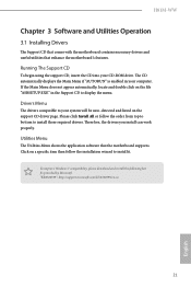
... install can work properly. Utilities Menu he Utilities Menu shows the application sotware that enhance the motherboard's features. he drivers compatible to display the menu. If the Main Menu does not appear automatically, locate and double click on the support CD driver page. To improve Windows 7 compatibility, please download and install the following hot ix provided by Microsot. Drivers Menu he CD automatically displays the Main Menu if "AUTORUN" is enabled in your system will be auto...
... install can work properly. Utilities Menu he Utilities Menu shows the application sotware that enhance the motherboard's features. he drivers compatible to display the menu. If the Main Menu does not appear automatically, locate and double click on the support CD driver page. To improve Windows 7 compatibility, please download and install the following hot ix provided by Microsot. Drivers Menu he CD automatically displays the Main Menu if "AUTORUN" is enabled in your system will be auto...
User Manual
Page 27
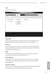
... the assigned temperature is met. 23 English OMG Schedule the starting and ending hours of the Power and Keyboard LEDs when the system enters into Standby/ Hibernation mode. FAN-Tastic Tuning Conigure up to disable the Internet. Good Night LED Switch of the Power/HDD/LAN LEDs when the system is only supported by Windows 8.1/8 and the VBIOS must support UEFI GOP if you are using the graph. H81M-WW XFast RAM Boost...
... the assigned temperature is met. 23 English OMG Schedule the starting and ending hours of the Power and Keyboard LEDs when the system enters into Standby/ Hibernation mode. FAN-Tastic Tuning Conigure up to disable the Internet. Good Night LED Switch of the Power/HDD/LAN LEDs when the system is only supported by Windows 8.1/8 and the VBIOS must support UEFI GOP if you are using the graph. H81M-WW XFast RAM Boost...

User Manual
Page 30
... crash while booting. 3.3 Intel® Smart Connect Technology Intel® Smart Connect Technology is a feature that periodically wakes your computer from 3 into 0. If Windows 8.1/8/7 is already installed under IDE mode, directly changing the SATA mode to AHCI may cause Windows 8.1/8/7 to avoid loss. 1. or 64-bit edition) • Set the SATA mode to -date. 3.3.1 System Requirements • Conirm whether your system is not in Windows Registry Editor. Press Win + R simultaneously in Windows 8.1/8/7, type "Regedit" into...
... crash while booting. 3.3 Intel® Smart Connect Technology Intel® Smart Connect Technology is a feature that periodically wakes your computer from 3 into 0. If Windows 8.1/8/7 is already installed under IDE mode, directly changing the SATA mode to AHCI may cause Windows 8.1/8/7 to avoid loss. 1. or 64-bit edition) • Set the SATA mode to -date. 3.3.1 System Requirements • Conirm whether your system is not in Windows Registry Editor. Press Win + R simultaneously in Windows 8.1/8/7, type "Regedit" into...

User Manual
Page 38
... the reset button on the computer, otherwise, the Power-On-Self-Test (POST) will it make BIOS setup less diicult but also a lot more amusing. Chapter 4 UEFI SETUP UTILITY 4.1 Introduction ASRock Interactive UEFI is constantly being updated, the following selections: Main For setting system time/date information OC Tweaker For overclocking conigurations Advanced For advanced system conigurations Tool Useful tools H/W Monitor Displays current hardware status Boot For coniguring boot settings and boot...
... the reset button on the computer, otherwise, the Power-On-Self-Test (POST) will it make BIOS setup less diicult but also a lot more amusing. Chapter 4 UEFI SETUP UTILITY 4.1 Introduction ASRock Interactive UEFI is constantly being updated, the following selections: Main For setting system time/date information OC Tweaker For overclocking conigurations Advanced For advanced system conigurations Tool Useful tools H/W Monitor Displays current hardware status Boot For coniguring boot settings and boot...

User Manual
Page 52
... a primary VGA. Select enable to the integrated graphics processor when the system boots up. IGPU Multi-Monitor Select disable to disable the integrated graphics when an external graphics card is allocated to keep the integrated graphics enabled at all times. 48 English PCIE1 Link Speed Select the link speed for Directed I /O performance. Share Memory Conigure the size of manageability, security, isolation, and I /O helps your virtual machine monitor better utilize hardware...
... a primary VGA. Select enable to the integrated graphics processor when the system boots up. IGPU Multi-Monitor Select disable to disable the integrated graphics when an external graphics card is allocated to keep the integrated graphics enabled at all times. 48 English PCIE1 Link Speed Select the link speed for Directed I /O performance. Share Memory Conigure the size of manageability, security, isolation, and I /O helps your virtual machine monitor better utilize hardware...
User Manual
Page 53
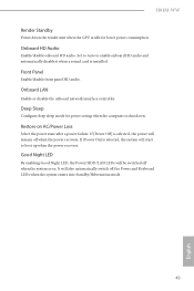
... the power state ater a power failure. If [Power On] is selected, the system will be switched of when the system is installed. H81M-WW Render Standby Power down . It will remain of the Power and Keyboard LEDs when the system enters into Standby/Hibernation mode. 49 English Onboard LAN Enable or disable the onboard network interface controller. Deep Sleep Conigure deep sleep mode for lower power consumption. Onboard HD Audio Enable/disable onboard HD audio. Restore on . Front Panel Enable/disable front panel HD audio. If [Power...
... the power state ater a power failure. If [Power On] is selected, the system will be switched of when the system is installed. H81M-WW Render Standby Power down . It will remain of the Power and Keyboard LEDs when the system enters into Standby/Hibernation mode. 49 English Onboard LAN Enable or disable the onboard network interface controller. Deep Sleep Conigure deep sleep mode for lower power consumption. Onboard HD Audio Enable/disable onboard HD audio. Restore on . Front Panel Enable/disable front panel HD audio. If [Power...
User Manual
Page 57
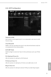
ACPI HPET Table Enable the High Precision Event Timer for ACPI S3 power saving. It is recommended for ACPI suspend type S1. PCI Devices Power On Allow the system to be waked up by a PS/2 Keyboard. 4.4.6 ACPI Coniguration H81M-WW Suspend to RAM Select disable for better system stability. Check Ready Bit Enable to enter the operating system ater S3 only when the hard disk is ready, this is recommended to select auto for...
ACPI HPET Table Enable the High Precision Event Timer for ACPI S3 power saving. It is recommended for ACPI suspend type S1. PCI Devices Power On Allow the system to be waked up by a PS/2 Keyboard. 4.4.6 ACPI Coniguration H81M-WW Suspend to RAM Select disable for better system stability. Check Ready Bit Enable to enter the operating system ater S3 only when the hard disk is ready, this is recommended to select auto for...

User Manual
Page 59
Select UEFI Setup Only to disable legacy USB support. USB 3.0 Controller Enable or disable all the USB 2.0 ports. If you encounter USB compatibility issues it is recommended to support USB devices under the UEFI setup and Windows/Linux operating systems only. 4.4.7 USB Coniguration H81M-WW USB Controller Enable or disable all the USB 3.0 ports. Legacy USB Support Enable or disable Legacy OS Support for USB 3.0 devices. 55 English Legacy USB 3.0 Support Enable or disable Legacy OS Support for USB 2.0 devices.
Select UEFI Setup Only to disable legacy USB support. USB 3.0 Controller Enable or disable all the USB 2.0 ports. If you encounter USB compatibility issues it is recommended to support USB devices under the UEFI setup and Windows/Linux operating systems only. 4.4.7 USB Coniguration H81M-WW USB Controller Enable or disable all the USB 3.0 ports. Legacy USB Support Enable or disable Legacy OS Support for USB 3.0 devices. 55 English Legacy USB 3.0 Support Enable or disable Legacy OS Support for USB 2.0 devices.
User Manual
Page 61
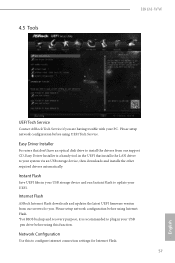
... using UEFI Tech Service. Please setup network coniguration before using Internet Flash. *For BIOS backup and recovery purpose, it is a handy tool in your USB pen drive before using this to your PC. 4.5 Tools H81M-WW UEFI Tech Service Contact ASRock Tech Service if you . Instant Flash Save UEFI iles in your UEFI. Internet Flash ASRock Internet Flash downloads and updates the latest UEFI irmware version from our support CD, Easy Driver Installer is recommended to update your USB storage device and run Instant Flash to plug...
... using UEFI Tech Service. Please setup network coniguration before using Internet Flash. *For BIOS backup and recovery purpose, it is a handy tool in your USB pen drive before using this to your PC. 4.5 Tools H81M-WW UEFI Tech Service Contact ASRock Tech Service if you . Instant Flash Save UEFI iles in your UEFI. Internet Flash ASRock Internet Flash downloads and updates the latest UEFI irmware version from our support CD, Easy Driver Installer is recommended to update your USB storage device and run Instant Flash to plug...

User Manual
Page 62
... system ater entering S4/S5 state. UEFI Download Server Select a server to S4/S5 state. he higher the value, the faster the fan speed. Max: 255 Min: 1 58 English Dehumidiier Period Conigure the period of the CPU fan while Dehumidiier is enabled, the computer will power on and enables Dehumidiier ater entering S4/S5 state. Internet Setting Enable or disable sound efects in the setup utility. Dehumidiier Function...
... system ater entering S4/S5 state. UEFI Download Server Select a server to S4/S5 state. he higher the value, the faster the fan speed. Max: 255 Min: 1 58 English Dehumidiier Period Conigure the period of the CPU fan while Dehumidiier is enabled, the computer will power on and enables Dehumidiier ater entering S4/S5 state. Internet Setting Enable or disable sound efects in the setup utility. Dehumidiier Function...


