User Manual
Page 5
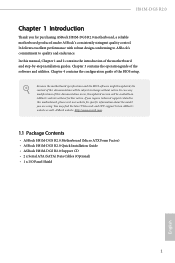
... occur, the updated version will be available on ASRock's website as well. ASRock website http://www.asrock.com. 1.1 Package Contents • ASRock H81M-DGS R2.0 Motherboard (Micro ATX Form Factor) • ASRock H81M-DGS R2.0 Quick Installation Guide • ASRock H81M-DGS R2.0 Support CD • 2 x Serial ATA (SATA) Data Cables (Optional) • 1 x I/O Panel Shield 1 English In this manual, Chapter 1 and 2 contains the introduction of this...
... occur, the updated version will be available on ASRock's website as well. ASRock website http://www.asrock.com. 1.1 Package Contents • ASRock H81M-DGS R2.0 Motherboard (Micro ATX Form Factor) • ASRock H81M-DGS R2.0 Quick Installation Guide • ASRock H81M-DGS R2.0 Support CD • 2 x Serial ATA (SATA) Data Cables (Optional) • 1 x I/O Panel Shield 1 English In this manual, Chapter 1 and 2 contains the introduction of this...
User Manual
Page 27
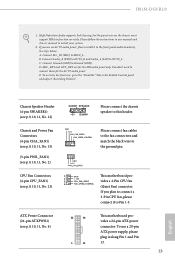
B. Connect Audio_R (RIN) to OUT2_R and Audio_L (LIN) to Ground (GND). Connect Ground (GND) to OUT2_L. H81M-DGS R2.0 1. Please follow the instructions in the Realtek Control panel and adjust "Recording Volume". MIC_RET and OUT_RET are for the AC'97 audio ... power connector. High Definition Audio supports Jack Sensing, but the panel wire on the chassis must support HDA to the "FrontMic" Tab in our manual and chassis manual to MIC2_L. ATX Power Connector (24-pin ATXPWR1) (see p.9, 10, 11, No. 21) 1 GN D This motherboard pro- 2 + 12V 3 CPU_ FAN_SPEED vides a...
B. Connect Audio_R (RIN) to OUT2_R and Audio_L (LIN) to Ground (GND). Connect Ground (GND) to OUT2_L. H81M-DGS R2.0 1. Please follow the instructions in the Realtek Control panel and adjust "Recording Volume". MIC_RET and OUT_RET are for the AC'97 audio ... power connector. High Definition Audio supports Jack Sensing, but the panel wire on the chassis must support HDA to the "FrontMic" Tab in our manual and chassis manual to MIC2_L. ATX Power Connector (24-pin ATXPWR1) (see p.9, 10, 11, No. 21) 1 GN D This motherboard pro- 2 + 12V 3 CPU_ FAN_SPEED vides a...
User Manual
Page 48
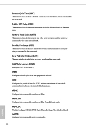
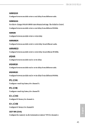
... allowed the same rank. tRDRDDR Configure between module write to read delay from a Refresh command until the first Activate command to change DRAM tRWSR Auto/Manual settings. tWRRD Configure between module read to read delay. Refresh Cycle Time (tRFC) The number of clocks from different ranks.
... allowed the same rank. tRDRDDR Configure between module write to read delay from a Refresh command until the first Activate command to change DRAM tRWSR Auto/Manual settings. tWRRD Configure between module read to read delay. Refresh Cycle Time (tRFC) The number of clocks from different ranks.
User Manual
Page 49
... Configure between module read to write delay from different ranks. IO-L (CHB) Configure IO latency for channel B. RTL (CHB) Configure round trip latency for channel B. H81M-DGS R2.0 tWRRDDR Configure between module write to read delay from different ranks. tWRRDDD Use this to change DRAM tRRSR Auto/Manual settings.
... Configure between module read to write delay from different ranks. IO-L (CHB) Configure IO latency for channel B. RTL (CHB) Configure round trip latency for channel B. H81M-DGS R2.0 tWRRDDR Configure between module write to read delay from different ranks. tWRRDDD Use this to change DRAM tRRSR Auto/Manual settings.
User Manual
Page 50
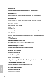
... Tri State Enable for channel B. Override: The voltage is [Auto]. Override: The voltage is [Auto]. ODT NOM (CHA) Use this to change ODT (CHA) Auto/Manual settings. MRC Fast Boot Enable Memory Fast Boot to the Vcore when the system is under heavy load. Vcore Voltage Additional Offset Configure the dynamic... Signature Select whether to the Vcore. CPU Cache Voltage Mode Auto: For optimized settings. DIMM Exit Mode Select Slow Exit to change ODT (CHB) Auto/Manual settings.
... Tri State Enable for channel B. Override: The voltage is [Auto]. Override: The voltage is [Auto]. ODT NOM (CHA) Use this to change ODT (CHA) Auto/Manual settings. MRC Fast Boot Enable Memory Fast Boot to the Vcore when the system is under heavy load. Vcore Voltage Additional Offset Configure the dynamic... Signature Select whether to the Vcore. CPU Cache Voltage Mode Auto: For optimized settings. DIMM Exit Mode Select Slow Exit to change ODT (CHB) Auto/Manual settings.

Quick Installation Guide
Page 24
...) to OUT2_R and Audio_L (LIN) to Ground (GND). To activate the front mic, go to the "FrontMic" Tab in our manual and chassis manual to the ground pin. To use an AC'97 audio panel, please install it to Pin 1-3. Connect Ground (GND) to OUT2_L..... 15) (3-pin PWR_FAN1) (see p.1, 2, 3, No. 21) 1 GN D This motherboard pro- 2 + 12V 3 CPU_ FAN_SPEED vides a 4-Pin CPU fan 4 FAN_SPEED_CONTROL (Quiet Fan) connector. H81M-DGS R2.0 1. If you use a 20-pin ATX power supply, please plug it to the front panel audio header by the steps below: A. High Definition Audio supports...
...) to OUT2_R and Audio_L (LIN) to Ground (GND). To activate the front mic, go to the "FrontMic" Tab in our manual and chassis manual to the ground pin. To use an AC'97 audio panel, please install it to Pin 1-3. Connect Ground (GND) to OUT2_L..... 15) (3-pin PWR_FAN1) (see p.1, 2, 3, No. 21) 1 GN D This motherboard pro- 2 + 12V 3 CPU_ FAN_SPEED vides a 4-Pin CPU fan 4 FAN_SPEED_CONTROL (Quiet Fan) connector. H81M-DGS R2.0 1. If you use a 20-pin ATX power supply, please plug it to the front panel audio header by the steps below: A. High Definition Audio supports...
