
User Manual
Page 6
...using. Chapter 4 contains the configuration guide of the software and utilities. ASRock website http://www.asrock.com. 1.1 Package Contents • ASRock H81 Pro BTC R2.0 Motherboard (ATX Form Factor) • ASRock H81 Pro BTC R2.0 Quick Installation Guide • ASRock H81 Pro BTC R2.0 Support CD • 2 x Serial ATA (SATA) Data Cables...available on ASRock's website as well. You may find the latest VGA cards and CPU support list on ASRock's website without notice. H81 Pro BTC R2.0 Chapter 1 Introduction Thank you require technical support related to this manual, Chapter ...
...using. Chapter 4 contains the configuration guide of the software and utilities. ASRock website http://www.asrock.com. 1.1 Package Contents • ASRock H81 Pro BTC R2.0 Motherboard (ATX Form Factor) • ASRock H81 Pro BTC R2.0 Quick Installation Guide • ASRock H81 Pro BTC R2.0 Support CD • 2 x Serial ATA (SATA) Data Cables...available on ASRock's website as well. You may find the latest VGA cards and CPU support list on ASRock's website without notice. H81 Pro BTC R2.0 Chapter 1 Introduction Thank you require technical support related to this manual, Chapter ...
User Manual
Page 24
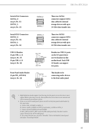
If you use an AC'97 audio panel, please install it to the "FrontMic" Tab in our manual and chassis manual to Ground (GND). You don't need to connect them for internal storage devices with up to function correctly. To activate the front ...(see p.6, No. 22) GND PRESENCE# MIC_RET OUT_RET 1 OUT2_L J_SENSE OUT2_R MIC2_R MIC2_L This header is for connecting audio devices to 6.0 Gb/s data transfer rate. D. H81 Pro BTC R2.0 Serial ATA2 Connectors (SATA2_0: see p.6, No. 11) (SATA2_1: see p.6, No. 13) SATA2_0 SATA2_1 These two SATA2 connectors support SATA data cables for the AC...
If you use an AC'97 audio panel, please install it to the "FrontMic" Tab in our manual and chassis manual to Ground (GND). You don't need to connect them for internal storage devices with up to function correctly. To activate the front ...(see p.6, No. 22) GND PRESENCE# MIC_RET OUT_RET 1 OUT2_L J_SENSE OUT2_R MIC2_R MIC2_L This header is for connecting audio devices to 6.0 Gb/s data transfer rate. D. H81 Pro BTC R2.0 Serial ATA2 Connectors (SATA2_0: see p.6, No. 11) (SATA2_1: see p.6, No. 13) SATA2_0 SATA2_1 These two SATA2 connectors support SATA data cables for the AC...

User Manual
Page 27
... graphics cards. A 1 2 B If your MB's TWO 4-pin power connectors. otherwise, the motherboard may be damaged. Then plug another PSU's 4-pin power connector ( 2 ) to the user manual that comes with your motherboard; Please MUST install TWO PSU's 4-pin power cables to your PSU only provides ONE, then please MUST install it to...
... graphics cards. A 1 2 B If your MB's TWO 4-pin power connectors. otherwise, the motherboard may be damaged. Then plug another PSU's 4-pin power connector ( 2 ) to the user manual that comes with your motherboard; Please MUST install TWO PSU's 4-pin power cables to your PSU only provides ONE, then please MUST install it to...

User Manual
Page 47
.... CAS Write Latency (tCWL) Configure CAS Write Latency. Refresh Cycle Time (tRFC) The number of clocks from different ranks. RAS to change DRAM tRWSR Auto/Manual settings.
.... CAS Write Latency (tCWL) Configure CAS Write Latency. Refresh Cycle Time (tRFC) The number of clocks from different ranks. RAS to change DRAM tRWSR Auto/Manual settings.

User Manual
Page 48
... write to write delay. tWRWRDD Configure between module write to write delay from different DIMMs. tRDWR Configure between module read to change DRAM tRRSR Auto/Manual settings. tWRRDDD Use this to write delay from different DIMMs. RTL (CHA) Configure round trip latency for channel A. ODT WR (CHA) Configure the ...for channel A. tWRWRDR Configure between module write to write delay from different ranks. The default is [Auto]. IO-L (CHA) Configure IO latency for channel B. H81 Pro BTC R2.0 tWRRDDR Configure between module write to read to write delay from different ranks.
... write to write delay. tWRWRDD Configure between module write to write delay from different DIMMs. tRDWR Configure between module read to change DRAM tRRSR Auto/Manual settings. tWRRDDD Use this to write delay from different DIMMs. RTL (CHA) Configure round trip latency for channel A. ODT WR (CHA) Configure the ...for channel A. tWRWRDR Configure between module write to write delay from different ranks. The default is [Auto]. IO-L (CHA) Configure IO latency for channel B. H81 Pro BTC R2.0 tWRRDDR Configure between module write to read to write delay from different ranks.
User Manual
Page 49
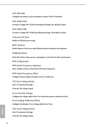
.... The default is fixed. 44 English FIVR Configuration FIVR Switch Frequency Signature Select whether to change ODT (CHB) Auto/Manual settings. Vcore Override Voltage Configure the voltage added to change ODT (CHA) Auto/Manual settings. Override: The voltage is [Auto]. The default is fixed. ODT NOM (CHB) Use this to boost or...
.... The default is fixed. 44 English FIVR Configuration FIVR Switch Frequency Signature Select whether to change ODT (CHB) Auto/Manual settings. Vcore Override Voltage Configure the voltage added to change ODT (CHA) Auto/Manual settings. Override: The voltage is [Auto]. The default is fixed. ODT NOM (CHB) Use this to boost or...
