User Manual
Page 10
... download files simultaneously. SmartView, a new function of previously visited websites, making web surfing faster than ever. ASRock XFast USB can easily enjoy the marvelous charging experience than ever. The performance may depend on the motherboard functions properly and unplug ...PC system. 13. ASRock motherboards are currently transferring. 11. 7. ASRock XFast RAM fully utilizes the memory space that cannot be noticed that it reduces the frequency of charging your computer and up to adopt three different CPU cooler types, Socket LGA 775, LGA 1155 and LGA 1156. ...
... download files simultaneously. SmartView, a new function of previously visited websites, making web surfing faster than ever. ASRock XFast USB can easily enjoy the marvelous charging experience than ever. The performance may depend on the motherboard functions properly and unplug ...PC system. 13. ASRock motherboards are currently transferring. 11. 7. ASRock XFast RAM fully utilizes the memory space that cannot be noticed that it reduces the frequency of charging your computer and up to adopt three different CPU cooler types, Socket LGA 775, LGA 1155 and LGA 1156. ...

User Manual
Page 12
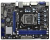
... USB8_9 1 SATA2_3 SATA2_1 SPEAKER1 1 CHA_FAN1 8 COM1 USB6_7 PLED PWRBTN 1 1 1 HDLED RESET PANEL1 SATA2_2 SATA2_0 19 18 17 16 15 14 13 12 11 10 9 1 1155-Pin CPU Socket 2 ATX 12V Power Connector (ATX12V1) 3 CPU Fan Connector (CPU_FAN1) 4 ATX Power Connector (ATXPWR1) 5 2 x 240-pin DDR3 DIMM Slots (Dual Channel: DDR3_A1, DDR3_B1, Blue) 6 Intel...
... USB8_9 1 SATA2_3 SATA2_1 SPEAKER1 1 CHA_FAN1 8 COM1 USB6_7 PLED PWRBTN 1 1 1 HDLED RESET PANEL1 SATA2_2 SATA2_0 19 18 17 16 15 14 13 12 11 10 9 1 1155-Pin CPU Socket 2 ATX 12V Power Connector (ATX12V1) 3 CPU Fan Connector (CPU_FAN1) 4 ATX Power Connector (ATXPWR1) 5 2 x 240-pin DDR3 DIMM Slots (Dual Channel: DDR3_A1, DDR3_B1, Blue) 6 Intel...
User Manual
Page 15
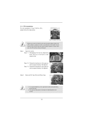
... hook to fully open position at approximately 100 degrees. Open the socket: Step 1-1. It is found. Step 1-2. Step 1-3. Step 2. Remove PnP Cap (Pick and Place Cap). 1. 2.3 CPU Installation For the installation of Intel 1155-Pin CPU, please follow the steps below. Rotate the load plate...lever to handle and avoid kicking off the PnP cap. 2. Load Plate Load Lever Contact Array Socket Body 1155-Pin Socket Overview Before you insert the 1155-Pin CPU into the socket if above situation is recommended to use the cap tab to fully open position at approximately 135 degrees...
... hook to fully open position at approximately 100 degrees. Open the socket: Step 1-1. It is found. Step 1-2. Step 1-3. Step 2. Remove PnP Cap (Pick and Place Cap). 1. 2.3 CPU Installation For the installation of Intel 1155-Pin CPU, please follow the steps below. Rotate the load plate...lever to handle and avoid kicking off the PnP cap. 2. Load Plate Load Lever Contact Array Socket Body 1155-Pin Socket Overview Before you insert the 1155-Pin CPU into the socket if above situation is recommended to use the cap tab to fully open position at approximately 135 degrees...
User Manual
Page 16
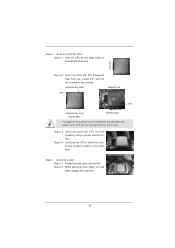
...vertical motion. Locate Pin1 and the two orientation key notches. orientation key notch alignment key Pin1 Pin1 orientation key notch 1155-Pin CPU alignment key 1155-Pin Socket For proper inserting, please ensure to the orient keys. Rotate the load plate onto the IHS. Verify that the CPU... is marked with black line. Step 4. Close the socket: Step 4-1. Step 3-3. black line Step 3-2. While pressing down lightly on load plate...
...vertical motion. Locate Pin1 and the two orientation key notches. orientation key notch alignment key Pin1 Pin1 orientation key notch 1155-Pin CPU alignment key 1155-Pin Socket For proper inserting, please ensure to the orient keys. Rotate the load plate onto the IHS. Verify that the CPU... is marked with black line. Step 4. Close the socket: Step 4-1. Step 3-3. black line Step 3-2. While pressing down lightly on load plate...
User Manual
Page 17
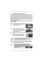
... this motherboard supports Combo Cooler Option (C.C.O.), which provides the flexible option to adopt three different CPU cooler types, Socket LGA 775, LGA 1155 and LGA 1156. Step 4. Ensure fan cables are oriented on side closest to the CPU fan connector on fastener caps with ...contact with each other components. 2.4 Installation of CPU Fan and Heatsink This motherboard is an example to illustrate the installation of the heatsink for Socket LGA 1155/1156 CPU fan. 17 Before you installed the heatsink, you press down on the motherboard (CPU_ FAN1, see page 12, No. 3). Ensure...
... this motherboard supports Combo Cooler Option (C.C.O.), which provides the flexible option to adopt three different CPU cooler types, Socket LGA 775, LGA 1155 and LGA 1156. Step 4. Ensure fan cables are oriented on side closest to the CPU fan connector on fastener caps with ...contact with each other components. 2.4 Installation of CPU Fan and Heatsink This motherboard is an example to illustrate the installation of the heatsink for Socket LGA 1155/1156 CPU fan. 17 Before you installed the heatsink, you press down on the motherboard (CPU_ FAN1, see page 12, No. 3). Ensure...

Quick Installation Guide
Page 2
...SATA2_1 SPEAKER1 1 CHA_FAN1 8 COM1 USB6_7 PLED PWRBTN 1 1 1 HDLED RESET PANEL1 SATA2_2 SATA2_0 19 18 17 16 15 14 13 12 11 10 9 1 1155-Pin CPU Socket 2 ATX 12V Power Connector (ATX12V1) 3 CPU Fan Connector (CPU_FAN1) 4 ATX Power Connector (ATXPWR1) 5 2 x 240-pin DDR3 DIMM Slots (Dual ... x1 Slot (PCIE2, White) 21 Clear CMOS Jumper (CLRCMOS1) 22 PCI Express 3.0 x16 Slot (PCIE1, Blue) 23 Power Fan Connector (PWR_FAN1) 2 ASRock H71M-DGS Motherboard English D G S PWR_FAN1 LAN PHY 5 22 PCIE1 Designed in ) DDR3_B1 (64 bit, 240-pin module) DDR3_A1 (64 bit, 240-pin module...
...SATA2_1 SPEAKER1 1 CHA_FAN1 8 COM1 USB6_7 PLED PWRBTN 1 1 1 HDLED RESET PANEL1 SATA2_2 SATA2_0 19 18 17 16 15 14 13 12 11 10 9 1 1155-Pin CPU Socket 2 ATX 12V Power Connector (ATX12V1) 3 CPU Fan Connector (CPU_FAN1) 4 ATX Power Connector (ATXPWR1) 5 2 x 240-pin DDR3 DIMM Slots (Dual ... x1 Slot (PCIE2, White) 21 Clear CMOS Jumper (CLRCMOS1) 22 PCI Express 3.0 x16 Slot (PCIE1, Blue) 23 Power Fan Connector (PWR_FAN1) 2 ASRock H71M-DGS Motherboard English D G S PWR_FAN1 LAN PHY 5 22 PCIE1 Designed in ) DDR3_B1 (64 bit, 240-pin module) DDR3_A1 (64 bit, 240-pin module...

Quick Installation Guide
Page 9
... the latency in order to adopt three different CPU cooler types, Socket LGA 775, LGA 1155 and LGA 1156. ASRock APP Charger. With APP Charger driver installed, you install the PC system. 13. Another advantage of ASRock XFast RAM is that helps you desire a faster, less restricted...the power cord, then plug it also boosts the speed of the device. 10. Before you can be used . 9 ASRock H71M-DGS Motherboard English 7. ASRock website: http://www.asrock.com/Feature/AppCharger/index.asp 8. Traffic Shaping: You can boost USB storage device performance. Please be noticed that ...
... the latency in order to adopt three different CPU cooler types, Socket LGA 775, LGA 1155 and LGA 1156. ASRock APP Charger. With APP Charger driver installed, you install the PC system. 13. Another advantage of ASRock XFast RAM is that helps you desire a faster, less restricted...the power cord, then plug it also boosts the speed of the device. 10. Before you can be used . 9 ASRock H71M-DGS Motherboard English 7. ASRock website: http://www.asrock.com/Feature/AppCharger/index.asp 8. Traffic Shaping: You can boost USB storage device performance. Please be noticed that ...

Quick Installation Guide
Page 11
... the motherboard. 2.1 CPU Installation For the installation of the following precautions before you insert the 1155-Pin CPU into the socket, please check if the CPU surface is unclean or if there is found. English 11 ASRock H71M-DGS Motherboard Doing so may cause severe damage to the chassis, please do not touch the ICs...
... the motherboard. 2.1 CPU Installation For the installation of the following precautions before you insert the 1155-Pin CPU into the socket, please check if the CPU surface is unclean or if there is found. English 11 ASRock H71M-DGS Motherboard Doing so may cause severe damage to the chassis, please do not touch the ICs...
Quick Installation Guide
Page 12
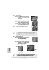
... recommended to use the cap tab to match the two orientation key notches of the CPU with the two alignment keys of the socket. 12 ASRock H71M-DGS Motherboard Insert the 1155-Pin CPU: Step 3-1. Step 1. black line English 1. Step 3. Hold the CPU by depressing down and out on the hook to fully open position...
... recommended to use the cap tab to match the two orientation key notches of the CPU with the two alignment keys of the socket. 12 ASRock H71M-DGS Motherboard Insert the 1155-Pin CPU: Step 3-1. Step 1. black line English 1. Step 3. Hold the CPU by depressing down and out on the hook to fully open position...
Quick Installation Guide
Page 13
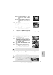
... CPU. Step 5. Step 1. Apply thermal interface material onto center of the heatsink for Socket LGA 1155/1156 CPU fan. 13 ASRock H71M-DGS Motherboard English Place the heatsink onto the socket. Carefully place the CPU into the socket by using a purely vertical motion. Rotate the fastener clockwise, then press down the fasteners without rotating them clockwise, the...
... CPU. Step 5. Step 1. Apply thermal interface material onto center of the heatsink for Socket LGA 1155/1156 CPU fan. 13 ASRock H71M-DGS Motherboard English Place the heatsink onto the socket. Carefully place the CPU into the socket by using a purely vertical motion. Rotate the fastener clockwise, then press down the fasteners without rotating them clockwise, the...