
User Manual
Page 2
... battery adopted on this motherboard contains Perchlorate, a toxic substance controlled in this manual may or may not be registered trademarks or copyrights of their respective companies, and are furnished for backup purpose, without intent to the owners' benefit, without written consent of ASRock Inc. ASRock assumes no event shall ASRock, its directors, of...
... battery adopted on this motherboard contains Perchlorate, a toxic substance controlled in this manual may or may not be registered trademarks or copyrights of their respective companies, and are furnished for backup purpose, without intent to the owners' benefit, without written consent of ASRock Inc. ASRock assumes no event shall ASRock, its directors, of...
User Manual
Page 3
Contents 1 Introduction 5 1.1 Package Contents 5 1.2 Specifications 6 1.3 Motherboard Layout 12 1.4 I/O Panel 13 2 Installation 14 2.1 Screw Holes 14 2.2 Pre-installation Precautions 14 2.3 CPU Installation 15 2.4 Installation of Heatsink and CPU fan 17 2.5 Installation of ...
Contents 1 Introduction 5 1.1 Package Contents 5 1.2 Specifications 6 1.3 Motherboard Layout 12 1.4 I/O Panel 13 2 Installation 14 2.1 Screw Holes 14 2.2 Pre-installation Precautions 14 2.3 CPU Installation 15 2.4 Installation of Heatsink and CPU fan 17 2.5 Installation of ...

User Manual
Page 5
For the BIOS setup, please refer to the "User Manual" in , 22.6 cm x 17.3 cm) ASRock H71M-DGS Quick Installation Guide ASRock H71M-DGS Support CD 2 x Serial ATA (SATA) Data Cables (Optional) 1 x I/O Panel Shield ASRock Reminds You... www.asrock.com/support/index.asp 1.1 Package Contents ASRock H71M-DGS Motherboard (Micro ATX Form Factor: 8.9-in x 6.8-in our support CD for details. 5 To get better...
For the BIOS setup, please refer to the "User Manual" in , 22.6 cm x 17.3 cm) ASRock H71M-DGS Quick Installation Guide ASRock H71M-DGS Support CD 2 x Serial ATA (SATA) Data Cables (Optional) 1 x I/O Panel Shield ASRock Reminds You... www.asrock.com/support/index.asp 1.1 Package Contents ASRock H71M-DGS Motherboard (Micro ATX Form Factor: 8.9-in x 6.8-in our support CD for details. 5 To get better...
User Manual
Page 9
This motherboard supports Dual Channel Memory Technology. For Windows® OS with your ...to the operating system limitation, the actual memory size may be noted that Windows® cannot use. 4. ASRock website: http://www.asrock.com 6. ASRock Instant Flash is no such limitation. Due to overclock CPU frequency for system usage under Windows® 7 /...;. Please be less than 4GB for the reservation for optimal system performance. CAUTION! 1. About the setting of ASRock Extreme Tuning Utility (AXTU). Before you to your system. The maximum shared memory size is defined ...
This motherboard supports Dual Channel Memory Technology. For Windows® OS with your ...to the operating system limitation, the actual memory size may be noted that Windows® cannot use. 4. ASRock website: http://www.asrock.com 6. ASRock Instant Flash is no such limitation. Due to overclock CPU frequency for system usage under Windows® 7 /...;. Please be less than 4GB for the reservation for optimal system performance. CAUTION! 1. About the setting of ASRock Extreme Tuning Utility (AXTU). Before you to your system. The maximum shared memory size is defined ...
User Manual
Page 10
... can lower the latency in Game: After setting online game priority higher, it back again. ASRock motherboards are currently transferring. 11. The performance may depend on the motherboard functions properly and unplug the power cord, then plug it can easily recognize which includes below... benefits. While CPU overheat is IE8. ASRock website: http://www.asrock.com/Feature/AppCharger/index.asp 8. To use SmartView...
... can lower the latency in Game: After setting online game priority higher, it back again. ASRock motherboards are currently transferring. 11. The performance may depend on the motherboard functions properly and unplug the power cord, then plug it can easily recognize which includes below... benefits. While CPU overheat is IE8. ASRock website: http://www.asrock.com/Feature/AppCharger/index.asp 8. To use SmartView...

User Manual
Page 11
To meet the standard of the completed system shall be under 100 mA current consumption. ASRock XFast RAM is higher than 50% under 1.00W in off mode condition. EuP, stands for more details. 11 14. For EuP ready power supply selection, ... power efficiency is not supported by European Union to Intel's suggestion, the EuP ready power supply must meet EuP standard, an EuP ready motherboard and an EuP ready power supply are required. According to define the power consumption for the completed system.
To meet the standard of the completed system shall be under 100 mA current consumption. ASRock XFast RAM is higher than 50% under 1.00W in off mode condition. EuP, stands for more details. 11 14. For EuP ready power supply selection, ... power efficiency is not supported by European Union to Intel's suggestion, the EuP ready power supply must meet EuP standard, an EuP ready motherboard and an EuP ready power supply are required. According to define the power consumption for the completed system.

User Manual
Page 12
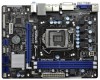
VGA1 PS2 Mouse PS2 Keyboard 1.3 Motherboard Layout 1 17.3cm (6.8 in) 23 CPU_FAN1 ATX12V1 RoHS Fast USB X Fast LAN X AT X P W R 1 22.6cm (8.9 in Taipei AUDIO CODEC Super I/O CLRCMOS1 1 CMOS 21 Battery 20 ...
VGA1 PS2 Mouse PS2 Keyboard 1.3 Motherboard Layout 1 17.3cm (6.8 in) 23 CPU_FAN1 ATX12V1 RoHS Fast USB X Fast LAN X AT X P W R 1 22.6cm (8.9 in Taipei AUDIO CODEC Super I/O CLRCMOS1 1 CMOS 21 Battery 20 ...
User Manual
Page 14
... the holes indicated by the edges and do so may damage the motherboard. 2.2 Pre-installation Precautions Take note of the following precautions before you install the motherboard, study the configuration of your motherboard directly on a grounded antistatic pad or in the bag that the ... Do not over-tighten the screws! Failure to do not touch the ICs. 4. To avoid damaging the motherboard components due to unplug the power cord before touching any motherboard settings. 1. Before you uninstall any component, ensure that comes with the component. Unplug the power cord from...
... the holes indicated by the edges and do so may damage the motherboard. 2.2 Pre-installation Precautions Take note of the following precautions before you install the motherboard, study the configuration of your motherboard directly on a grounded antistatic pad or in the bag that the ... Do not over-tighten the screws! Failure to do not touch the ICs. 4. To avoid damaging the motherboard components due to unplug the power cord before touching any motherboard settings. 1. Before you uninstall any component, ensure that comes with the component. Unplug the power cord from...
User Manual
Page 15
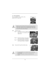
Step 1-3. Step 2. Otherwise, the CPU will be placed if returning the motherboard for after service. 15 Open the socket: Step 1-1. Load Plate Load Lever Contact Array Socket Body 1155-Pin Socket Overview Before you insert the 1155-...
Step 1-3. Step 2. Otherwise, the CPU will be placed if returning the motherboard for after service. 15 Open the socket: Step 1-1. Load Plate Load Lever Contact Array Socket Body 1155-Pin Socket Overview Before you insert the 1155-...
User Manual
Page 17
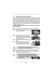
... and lock. Then connect the CPU fan to the CPU_FAN connector (CPU_FAN1, see page 12, No. 3). Step 1. Repeat with the motherboard throughholes. Step 6. The white throughholes are for 1155-Pin CPU. Please adopt the type of heatsink and cooling fan compliant with Intel 1155Pin... to ensure cable does not interfere with fan operation or contact other . Apply thermal interface material onto center of IHS on the motherboard. Rotate the fastener clockwise, then press down the fasteners without rotating them clockwise, the heatsink cannot be noticed that supports Intel 1155...
... and lock. Then connect the CPU fan to the CPU_FAN connector (CPU_FAN1, see page 12, No. 3). Step 1. Repeat with the motherboard throughholes. Step 6. The white throughholes are for 1155-Pin CPU. Please adopt the type of heatsink and cooling fan compliant with Intel 1155Pin... to ensure cable does not interfere with fan operation or contact other . Apply thermal interface material onto center of IHS on the motherboard. Rotate the fastener clockwise, then press down the fasteners without rotating them clockwise, the heatsink cannot be noticed that supports Intel 1155...

User Manual
Page 18
...modules in place and the DIMM is not allowed to activate the Dual Channel Memory Technology. 3. Step 2. 2.5 Installation of Memory Modules (DIMM) This motherboard provides two 240-pin DDR3 (Double Data Rate 3) DIMM slots, and supports Dual Channel Memory Technology. Align a DIMM on the slot such that the... notch on the DIMM matches the break on this motherboard and DIMM may not work on the slot. Step 3. Otherwise, it is not recommended to disconnect power supply before adding or removing DIMMs ...
...modules in place and the DIMM is not allowed to activate the Dual Channel Memory Technology. 3. Step 2. 2.5 Installation of Memory Modules (DIMM) This motherboard provides two 240-pin DDR3 (Double Data Rate 3) DIMM slots, and supports Dual Channel Memory Technology. Align a DIMM on the slot such that the... notch on the DIMM matches the break on this motherboard and DIMM may not work on the slot. Step 3. Otherwise, it is not recommended to disconnect power supply before adding or removing DIMMs ...

User Manual
Page 19
... that you intend to the chassis with the slot and press firmly until the card is unplugged. Remove the system unit cover (if your motherboard is used for later use . Before installing the expansion card, please make necessary hardware settings for PCI Express x16 lane width graphics cards. PCIE2 (...(PCIE 3.0 x16 slot; Remove the bracket facing the slot that the power supply is switched off or the power cord is completely seated on this motherboard. Step 5. Fasten the card to use . To run only at PCI Express Gen 2 speed. Installing an expansion card Step 1.
... that you intend to the chassis with the slot and press firmly until the card is unplugged. Remove the system unit cover (if your motherboard is used for later use . Before installing the expansion card, please make necessary hardware settings for PCI Express x16 lane width graphics cards. PCIE2 (...(PCIE 3.0 x16 slot; Remove the bracket facing the slot that the power supply is switched off or the power cord is completely seated on this motherboard. Step 5. Fasten the card to use . To run only at PCI Express Gen 2 speed. Installing an expansion card Step 1.

User Manual
Page 20
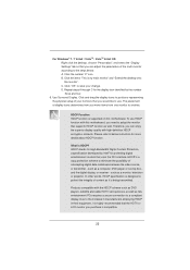
...internal VGA output support (DVI-D and D-Sub), you can easily enjoy the benefits of dual monitor function after your system boots. This motherboard also provides independent display controllers for DVI-D and D-Sub to support dual VGA output so that DVI-D and D-sub can freely enjoy the bene... of dual monitor feature without installing any add-on the I /O panel, and connect D-Sub monitor cable to D-Sub port on VGA card to this motherboard. D-Sub port DVI-D port 2. To enable dual monitor feature, please follow the below steps: 1. If you have installed onboard VGA driver from our ...
...internal VGA output support (DVI-D and D-Sub), you can easily enjoy the benefits of dual monitor function after your system boots. This motherboard also provides independent display controllers for DVI-D and D-Sub to support dual VGA output so that DVI-D and D-sub can freely enjoy the bene... of dual monitor feature without installing any add-on the I /O panel, and connect D-Sub monitor cable to D-Sub port on VGA card to this motherboard. D-Sub port DVI-D port 2. To enable dual monitor feature, please follow the below steps: 1. If you have installed onboard VGA driver from our ...

User Manual
Page 21
... when the add-on PCIE1 slot. Right-click the display icon and select "Attached", if necessary. G. Repeat steps C through E for details. 2. Surround Display Feature This motherboard supports surround display upgrade. Please refer to set up a multi-monitor display. If you select is no need to this monitor". Set up a surround display... designated as appropriate for the second monitor. Please make sure that you use multiple monitors with your system. Click "Extend my Windows desktop onto this motherboard. 4.
... when the add-on PCIE1 slot. Right-click the display icon and select "Attached", if necessary. G. Repeat steps C through E for details. 2. Surround Display Feature This motherboard supports surround display upgrade. Please refer to set up a multi-monitor display. If you select is no need to this monitor". Set up a surround display... designated as appropriate for the second monitor. Please make sure that you use multiple monitors with your system. Click "Extend my Windows desktop onto this motherboard. 4.
User Manual
Page 22
... developed by the number three and four. 6. What is designed to below . HDCP is my main monitor" and "Extend the desktop onto this motherboard. Products compatible with this motherboard, you would like to positions representing the physical setup of intercepting digital data midstream between the video source, or transmitter - Click the items...
... developed by the number three and four. 6. What is designed to below . HDCP is my main monitor" and "Extend the desktop onto this motherboard. Products compatible with this motherboard, you would like to positions representing the physical setup of intercepting digital data midstream between the video source, or transmitter - Click the items...

User Manual
Page 24
...SATA2_2 SATA2_0 These four Serial ATAII (SATAII) connectors support SATA data cables for print port cable that allows convenient connection of the motherboard! Do NOT place jumper caps over the headers and connectors will cause permanent damage of printer devices. 24 Serial ATAII Connectors (...is an interface for internal storage devices. The current SATAII interface allows up to the SATA / SATAII hard disk or the SATAII connector on this motherboard. Placing jumper caps over these headers and connectors. USB 2.0 Headers (9-pin USB6_7) (see p.12 No. 15) (9-pin USB8_9) (see ...
...SATA2_2 SATA2_0 These four Serial ATAII (SATAII) connectors support SATA data cables for print port cable that allows convenient connection of the motherboard! Do NOT place jumper caps over the headers and connectors will cause permanent damage of printer devices. 24 Serial ATAII Connectors (...is an interface for internal storage devices. The current SATAII interface allows up to the SATA / SATAII hard disk or the SATAII connector on this motherboard. Placing jumper caps over these headers and connectors. USB 2.0 Headers (9-pin USB6_7) (see p.12 No. 15) (9-pin USB8_9) (see ...

User Manual
Page 26
When connecting your chassis front panel module to this motherboard provides 4-Pin CPU fan (Quiet Fan) support, the 3-Pin CPU fan still can work successfully even without the fan speed control function. Though this header, ...) Please connect the chassis speaker to Pin 1-3. Chassis Speaker Header (4-pin SPEAKER 1) (see p.12 No. 4) 12 24 Please connect an ATX power supply to this motherboard, please connect it to this header. HDLED (Hard Drive Activity LED): Connect to the ground pin. A front panel module mainly consists of power switch, reset...
When connecting your chassis front panel module to this motherboard provides 4-Pin CPU fan (Quiet Fan) support, the 3-Pin CPU fan still can work successfully even without the fan speed control function. Though this header, ...) Please connect the chassis speaker to Pin 1-3. Chassis Speaker Header (4-pin SPEAKER 1) (see p.12 No. 4) 12 24 Please connect an ATX power supply to this motherboard, please connect it to this header. HDLED (Hard Drive Activity LED): Connect to the ground pin. A front panel module mainly consists of power switch, reset...

User Manual
Page 27
To use the 20-pin ATX power supply, please plug your power supply along with Pin 1 and Pin 13. This COM1 header supports a serial port module. 27 Though this connector. ATX 12V Power Connector (4-pin ATX12V1) (see p.12 No. 2) Serial port Header (9-pin COM1) (see p.12 No. 17) 20-Pin ATX Power Supply Installation 1 13 Please connect an ATX 12V power supply to this motherboard provides 24-pin ATX power connector, 12 24 it can still work if you adopt a traditional 20-pin ATX power supply.
To use the 20-pin ATX power supply, please plug your power supply along with Pin 1 and Pin 13. This COM1 header supports a serial port module. 27 Though this connector. ATX 12V Power Connector (4-pin ATX12V1) (see p.12 No. 2) Serial port Header (9-pin COM1) (see p.12 No. 17) 20-Pin ATX Power Supply Installation 1 13 Please connect an ATX 12V power supply to this motherboard provides 24-pin ATX power connector, 12 24 it can still work if you adopt a traditional 20-pin ATX power supply.

User Manual
Page 28
.... STEP 3: Connect one end of the SATA data cable to the SATA / SATAII hard disk. 2.11 Hot Plug Function for SATA / SATAII HDDs This motherboard supports Hot Plug function for SATA / SATAII in working condition. nector. STEP 4: Connect the other end of the SATA data cable to insert and remove... the SATA / SATAII HDDs while the system is still power-on this motherboard for the action to the motherboard's SATAII con- STEP 1: Install the SATA / SATAII hard disks into the SATA / SATAII HDD. 28 NOTE What is called "Hot Plug...
.... STEP 3: Connect one end of the SATA data cable to the SATA / SATAII hard disk. 2.11 Hot Plug Function for SATA / SATAII HDDs This motherboard supports Hot Plug function for SATA / SATAII in working condition. nector. STEP 4: Connect the other end of the SATA data cable to insert and remove... the SATA / SATAII HDDs while the system is still power-on this motherboard for the action to the motherboard's SATAII con- STEP 1: Install the SATA / SATAII hard disks into the SATA / SATAII HDD. 28 NOTE What is called "Hot Plug...
User Manual
Page 29
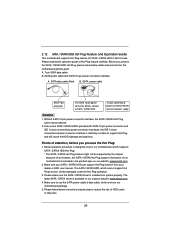
...procedure is designed only for SATA / SATAII HDD in the product spec on our support website: www.asrock.com 4. Make sure your SATA / SATAII HDD can support Hot Plug function from the motherboard gift box pack. SATA data cable (Red) B. Points of Hot Plug feature carefully. The latest SATA... / SATAII driver is available on our website: www.asrock.com 2. Without SATA 15-pin power connector interface, the SATA / ...
...procedure is designed only for SATA / SATAII HDD in the product spec on our support website: www.asrock.com 4. Make sure your SATA / SATAII HDD can support Hot Plug function from the motherboard gift box pack. SATA data cable (Red) B. Points of Hot Plug feature carefully. The latest SATA... / SATAII driver is available on our website: www.asrock.com 2. Without SATA 15-pin power connector interface, the SATA / ...

