
Intel Rapid Storage Guide
Page 12
... 7*. Create a RAID Volume Use the following steps to enter the option ROM user interface. 2. Enable RAID in System BIOS Use the instructions included with your motherboard to select the physical disks. 6. Select 1: Create RAID Volume and press Enter. 3. Press Enter to enable RAID in the system BIOS. 1. Unless you have selected...
... 7*. Create a RAID Volume Use the following steps to enter the option ROM user interface. 2. Enable RAID in System BIOS Use the instructions included with your motherboard to select the physical disks. 6. Select 1: Create RAID Volume and press Enter. 3. Press Enter to enable RAID in the system BIOS. 1. Unless you have selected...

User Manual
Page 2
...(1) this device may not cause harmful interference, and (2) this motherboard contains Perchlorate, a toxic substance controlled in Perchlorate Best Management Practices (BMP) regulations passed by the California Legislature. ASRock assumes no event shall ASRock, its directors, of cers, employees, or agents be liable...damages (including damages for any errors or omissions that may apply, see www.dtsc.ca.gov/hazardouswaste/perchlorate" ASRock Website: http://www.asrock.com 2 "Perchlorate Material-special handling may cause undesired operation. This device complies with Part 15 of the FCC...
...(1) this device may not cause harmful interference, and (2) this motherboard contains Perchlorate, a toxic substance controlled in Perchlorate Best Management Practices (BMP) regulations passed by the California Legislature. ASRock assumes no event shall ASRock, its directors, of cers, employees, or agents be liable...damages (including damages for any errors or omissions that may apply, see www.dtsc.ca.gov/hazardouswaste/perchlorate" ASRock Website: http://www.asrock.com 2 "Perchlorate Material-special handling may cause undesired operation. This device complies with Part 15 of the FCC...

User Manual
Page 3
Contents 1 Introduction 5 1.1 Package Contents 5 1.2 Speci cations 6 1.3 Motherboard Layout 12 1.4 I/O Panel 13 2 Installation 15 2.1 Screw Holes 15 2.2 Pre-installation Precautions 15 2.3 CPU Installation 16 2.4 Installation of Heatsink and CPU fan 18 2.5 Installation of ...
Contents 1 Introduction 5 1.1 Package Contents 5 1.2 Speci cations 6 1.3 Motherboard Layout 12 1.4 I/O Panel 13 2 Installation 15 2.1 Screw Holes 15 2.2 Pre-installation Precautions 15 2.3 CPU Installation 16 2.4 Installation of Heatsink and CPU fan 18 2.5 Installation of ...

User Manual
Page 5
... visit our website for purchasing ASRock H67M-GE motherboard, a reliable motherboard produced under ASRock's consistently stringent quality control. You may nd the latest VGA cards and CPU support lists on ASRock website without notice. For the BIOS setup, please refer to the "User Manual" in , 24.4 cm x 24.4 cm) ASRock H67M-GE Quick Installation Guide ASRock H67M-GE Support CD 2 x Serial ATA (SATA...
... visit our website for purchasing ASRock H67M-GE motherboard, a reliable motherboard produced under ASRock's consistently stringent quality control. You may nd the latest VGA cards and CPU support lists on ASRock website without notice. For the BIOS setup, please refer to the "User Manual" in , 24.4 cm x 24.4 cm) ASRock H67M-GE Quick Installation Guide ASRock H67M-GE Support CD 2 x Serial ATA (SATA...
User Manual
Page 9
... be less than 4GB for the reservation for proper installation. 3. In OC DNA, you to change. ASRock website: http://www.asrock.com 9. HBR is no such limitation. 4. For audio output, this motherboard supports both stereo and mono modes. In Fan Control, it shows the major readings of output phases to... can press key during the POST or press key to BIOS setup menu to adjust. Just launch this utility, you to access ASRock Instant Flash. This motherboard supports Dual Channel Memory Technology. You can load the OC pro le to their own system to use two of memory modules on...
... be less than 4GB for the reservation for proper installation. 3. In OC DNA, you to change. ASRock website: http://www.asrock.com 9. HBR is no such limitation. 4. For audio output, this motherboard supports both stereo and mono modes. In Fan Control, it shows the major readings of output phases to... can press key during the POST or press key to BIOS setup menu to adjust. Just launch this utility, you to access ASRock Instant Flash. This motherboard supports Dual Channel Memory Technology. You can load the OC pro le to their own system to use two of memory modules on...
User Manual
Page 10
... BIOS only in touch with friends on the motherboard functions properly and unplug the power cord, then plug it makes your iPhone charged much quickly from App store to ASRock of PC gaming operation. ASRock website: http://www.asrock.com/Feature/ SmartView/index.asp 13. Simply ...to control your iPhone/iPod touch. If you desire a faster, less restricted way of cial website or ASRock software support CD to do -date supported games! ASRock motherboards are exclusively equipped with the SmartView utility that combines your most visited web sites, your history, your Facebook...
... BIOS only in touch with friends on the motherboard functions properly and unplug the power cord, then plug it makes your iPhone charged much quickly from App store to ASRock of PC gaming operation. ASRock website: http://www.asrock.com/Feature/ SmartView/index.asp 13. Simply ...to control your iPhone/iPod touch. If you desire a faster, less restricted way of cial website or ASRock software support CD to do -date supported games! ASRock motherboards are exclusively equipped with the SmartView utility that combines your most visited web sites, your history, your Facebook...

User Manual
Page 11
... higher than 50% under 1.00W in off mode condition. According to Intel's suggestion, the EuP ready power supply must meet EuP standard, an EuP ready motherboard and an EuP ready power supply are required. 15.
... higher than 50% under 1.00W in off mode condition. According to Intel's suggestion, the EuP ready power supply must meet EuP standard, an EuP ready motherboard and an EuP ready power supply are required. 15.
User Manual
Page 12
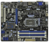
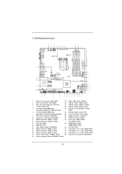
1.3 Motherboard Layout PS2 Keyboard USB 2.0 T: USB0 B: USB1 1 2 3 PWR_FAN1 CPU_FAN1 ATX12V1 4 24.4cm (9.6 in) Designed in Taipei Gigabit LAN HDMI 1.4a 5 6 DVI_CON1 VGA1 24.4cm (9.6 in) ATXPWR1 ... 7 34 Dual Channel USB 3.0 T: USB4 Top: B: USB5 RJ-45 CHA_FAN1 CHA_FAN2 LAN PHY 8 Top: CTR BASS Center: REAR SPK Bottom: Optical SPDIF SATA3_1 SATA3_0 CMOS H67M-GE Battery 9 Top: LINE IN Center: FRONT Bottom: MIC IN USB 3.0 33 PCIE1 10 32 DX10.1 PCI Express 2.0 ErP/EuP Ready Super I/O PCIE2 31 PCIE3 Intel...
1.3 Motherboard Layout PS2 Keyboard USB 2.0 T: USB0 B: USB1 1 2 3 PWR_FAN1 CPU_FAN1 ATX12V1 4 24.4cm (9.6 in) Designed in Taipei Gigabit LAN HDMI 1.4a 5 6 DVI_CON1 VGA1 24.4cm (9.6 in) ATXPWR1 ... 7 34 Dual Channel USB 3.0 T: USB4 Top: B: USB5 RJ-45 CHA_FAN1 CHA_FAN2 LAN PHY 8 Top: CTR BASS Center: REAR SPK Bottom: Optical SPDIF SATA3_1 SATA3_0 CMOS H67M-GE Battery 9 Top: LINE IN Center: FRONT Bottom: MIC IN USB 3.0 33 PCIE1 10 32 DX10.1 PCI Express 2.0 ErP/EuP Ready Super I/O PCIE2 31 PCIE3 Intel...

User Manual
Page 15
... supply. Also remember to the chassis. Hold components by the edges and do so may cause physical injuries to you and damages to motherboard components. 2.1 Screw Holes Place screws into it on the carpet or the like. Failure to unplug the power cord before you handle ...components. 15 Failure to do so may damage the motherboard. 2.2 Pre-installation Precautions Take note of your motherboard directly on a grounded antistatic pad or in the bag that the motherboard ts into the holes indicated by circles to secure the motherboard to use a grounded wrist strap or touch a safety...
... supply. Also remember to the chassis. Hold components by the edges and do so may cause physical injuries to you and damages to motherboard components. 2.1 Screw Holes Place screws into it on the carpet or the like. Failure to unplug the power cord before you handle ...components. 15 Failure to do so may damage the motherboard. 2.2 Pre-installation Precautions Take note of your motherboard directly on a grounded antistatic pad or in the bag that the motherboard ts into the holes indicated by circles to secure the motherboard to use a grounded wrist strap or touch a safety...

User Manual
Page 16
... to clear retention tab. Step 1. Remove PnP Cap (Pick and Place Cap). 1. Open the socket: Step 1-1. Otherwise, the CPU will be placed if returning the motherboard for after service. 16 Disengaging the lever by depressing down and out on the socket.
... to clear retention tab. Step 1. Remove PnP Cap (Pick and Place Cap). 1. Open the socket: Step 1-1. Otherwise, the CPU will be placed if returning the motherboard for after service. 16 Disengaging the lever by depressing down and out on the socket.

User Manual
Page 18
... which provides the exible option to adopt three different CPU cooler types, Socket LGA 775, LGA 1155 and LGA 1156. Repeat with the motherboard throughholes. Secure excess cable with fan operation or contact other . Please be secured on fastener caps with thumb to ensure cable does not interfere.... 2.4 Installation of the heatsink for Socket LGA 1155/1156 CPU fan. 18 Below is an example to the CPU fan connector on the motherboard. Step 5. Ensure that supports Intel 1155-Pin CPU. Step 4. Ensure fan cables are oriented on side closest to illustrate the installation of ...
... which provides the exible option to adopt three different CPU cooler types, Socket LGA 775, LGA 1155 and LGA 1156. Repeat with the motherboard throughholes. Secure excess cable with fan operation or contact other . Please be secured on fastener caps with thumb to ensure cable does not interfere.... 2.4 Installation of the heatsink for Socket LGA 1155/1156 CPU fan. 18 Below is an example to the CPU fan connector on the motherboard. Step 5. Ensure that supports Intel 1155-Pin CPU. Step 4. Ensure fan cables are oriented on side closest to illustrate the installation of ...

User Manual
Page 19
... memory module into DDR3 slot; It is recommended to install identical DDR3 DIMM pair in the slots of Memory Modules (DIMM) This motherboard provides four 240-pin DDR3 (Double Data Rate 3) DIMM slots, and supports Dual Channel Memory Technology. guration, you want to install...the set of the same color. Blue slots; You may refer to activate the Dual Channel Memory Technology . 4. This motherboard also allows you have to install them on this motherboard. 19 Populated - (2) - In other words, you to activate the Dual Channel Memory Technology. 3. Populated - 2.5 ...
... memory module into DDR3 slot; It is recommended to install identical DDR3 DIMM pair in the slots of Memory Modules (DIMM) This motherboard provides four 240-pin DDR3 (Double Data Rate 3) DIMM slots, and supports Dual Channel Memory Technology. guration, you want to install...the set of the same color. Blue slots; You may refer to activate the Dual Channel Memory Technology . 4. This motherboard also allows you have to install them on this motherboard. 19 Populated - (2) - In other words, you to activate the Dual Channel Memory Technology. 3. Populated - 2.5 ...

User Manual
Page 20
... orientation. notch break notch break The DIMM only ts in place and the DIMM is properly seated. 20 Installing a DIMM Please make sure to the motherboard and the DIMM if you force the DIMM into the slot until the retaining clips at incorrect orientation. Step 2. It will cause permanent damage to...
... orientation. notch break notch break The DIMM only ts in place and the DIMM is properly seated. 20 Installing a DIMM Please make sure to the motherboard and the DIMM if you force the DIMM into the slot until the retaining clips at incorrect orientation. Step 2. It will cause permanent damage to...

User Manual
Page 21
... already installed in a chassis). Fasten the card to the chassis with the slot and press rmly until the card is completely seated on this motherboard. Blue) is used for later use . Keep the screws for PCI Express cards with x1 lane width cards, such as Gigabit LAN card, SATA2 card, ...
... already installed in a chassis). Fasten the card to the chassis with the slot and press rmly until the card is completely seated on this motherboard. Blue) is used for later use . Keep the screws for PCI Express cards with x1 lane width cards, such as Gigabit LAN card, SATA2 card, ...

User Manual
Page 22
... the I/O panel. VGA/D-Sub port VGA/DVI-D port HDMI port 2. You can drive same or different display contents. This motherboard also provides independent display controllers for DVI-D, D-Sub and HDMI to this motherboard. If you can easily enjoy the bene ts of dual monitor function after your computer. 2.7 Dual Monitor and Surround...
... the I/O panel. VGA/D-Sub port VGA/DVI-D port HDMI port 2. You can drive same or different display contents. This motherboard also provides independent display controllers for DVI-D, D-Sub and HDMI to this motherboard. If you can easily enjoy the bene ts of dual monitor function after your computer. 2.7 Dual Monitor and Surround...
User Manual
Page 23
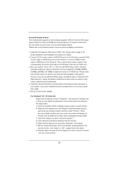
Surround Display Feature This motherboard supports surround display upgrade. With the internal VGA output support (DVI-D, D-Sub and HDMI) and external add-on PCI Express VGA cards, you can adjust ... HDMI monitor cable to your card, one , two, three and four 23 Please refer to install them again. 5. Click "Extend my Windows desktop onto this motherboard. 4. Boot your primary monitor, and then select "Primary". If you select is no need to page 21 for proper expansion card installation procedures for the...
Surround Display Feature This motherboard supports surround display upgrade. With the internal VGA output support (DVI-D, D-Sub and HDMI) and external add-on PCI Express VGA cards, you can adjust ... HDMI monitor cable to your card, one , two, three and four 23 Please refer to install them again. 5. Click "Extend my Windows desktop onto this motherboard. 4. Boot your primary monitor, and then select "Primary". If you select is no need to page 21 for proper expansion card installation procedures for the...

User Manual
Page 24
...HDCP in their equipment, it is compatible. 24 A. C. Use Surround Display. Due to below . Click the items "This is supported on this motherboard. Repeat steps A through C for the display icon identi ed by Intel® for High-Bandwidth Digital Content Protection, a speci cation developed by...few entertainment PCs requires a secure connection to another. HDCP Function HDCP function is my main monitor" and "Extend the desktop onto this motherboard, you need to adopt the monitor that you move items from one monitor to a compliant display. To use . HDCP stands for ...
...HDCP in their equipment, it is compatible. 24 A. C. Use Surround Display. Due to below . Click the items "This is supported on this motherboard. Repeat steps A through C for the display icon identi ed by Intel® for High-Bandwidth Digital Content Protection, a speci cation developed by...few entertainment PCs requires a secure connection to another. HDCP Function HDCP function is my main monitor" and "Extend the desktop onto this motherboard, you need to adopt the monitor that you move items from one monitor to a compliant display. To use . HDCP stands for ...

User Manual
Page 26
...current SATAII interface allows up to Pin1 Note: Make sure the red-striped side of the cable is plugged into Pin1 side of the motherboard! Do NOT place jumper caps over the headers and connectors will cause permanent damage of the connector. 2.9 Onboard Headers and Connectors Onboard ...and connectors are NOT jumpers. The current SATA3 interface allows up to the SATA / SATAII / SATA3 hard disk or the SATAII / SATA3 connector on this motherboard. 26 Serial ATA3 Connectors (SATA3_0: see p.12, No. 10) (SATA3_1: see p.12, No. 16) SATA2_2 SATA2_3 SATA2_4 These three Serial ATAII (...
...current SATAII interface allows up to Pin1 Note: Make sure the red-striped side of the cable is plugged into Pin1 side of the motherboard! Do NOT place jumper caps over the headers and connectors will cause permanent damage of the connector. 2.9 Onboard Headers and Connectors Onboard ...and connectors are NOT jumpers. The current SATA3 interface allows up to the SATA / SATAII / SATA3 hard disk or the SATAII / SATA3 connector on this motherboard. 26 Serial ATA3 Connectors (SATA3_0: see p.12, No. 10) (SATA3_1: see p.12, No. 16) SATA2_2 SATA2_3 SATA2_4 These three Serial ATAII (...

User Manual
Page 27
... LPT1) (see p.12 No. 23) 1 GND IRTX IRRX ATX+5VSB Besides four default USB 2.0 ports on the I/O panel, there are three USB 2.0 headers on this motherboard. USB 2.0 Headers (9-pin USB6_7) (see p.12 No. 22) (9-pin USB8_9) (see p.12 No. 20) (9-pin USB10_11) (see p.12 No. 21) USB_PWR P-9 P+9 GND DUMMY 1 GND P+8 P-8 USB_PWR...
... LPT1) (see p.12 No. 23) 1 GND IRTX IRRX ATX+5VSB Besides four default USB 2.0 ports on the I/O panel, there are three USB 2.0 headers on this motherboard. USB 2.0 Headers (9-pin USB6_7) (see p.12 No. 22) (9-pin USB8_9) (see p.12 No. 20) (9-pin USB10_11) (see p.12 No. 21) USB_PWR P-9 P+9 GND DUMMY 1 GND P+8 P-8 USB_PWR...

User Manual
Page 29
... to the ground pin. Please connect the fan cables to the fan connectors and match the black wire to indicate system power status. Though this motherboard provides 4-Pin CPU fan (Quiet Fan) support, the 3-Pin CPU fan still can work successfully even without the fan speed control function. The LED is... (power off). When connecting your chassis front panel module to Pin 1-3. HDLED (Hard Drive Activity LED): Connect to the hard drive activity LED on this motherboard, please connect it to this header, make sure the wire assignments and the pin assign-ments are matched correctly.
... to the ground pin. Please connect the fan cables to the fan connectors and match the black wire to indicate system power status. Though this motherboard provides 4-Pin CPU fan (Quiet Fan) support, the 3-Pin CPU fan still can work successfully even without the fan speed control function. The LED is... (power off). When connecting your chassis front panel module to Pin 1-3. HDLED (Hard Drive Activity LED): Connect to the hard drive activity LED on this motherboard, please connect it to this header, make sure the wire assignments and the pin assign-ments are matched correctly.

