
User Manual
Page 1
All rights reserved. 1 H67M-GE/HT User Manual Version 1.0 Published November 2010 Copyright©2010 ASRock INC.
All rights reserved. 1 H67M-GE/HT User Manual Version 1.0 Published November 2010 Copyright©2010 ASRock INC.

User Manual
Page 2
...: (1) this device may not cause harmful interference, and (2) this device must accept any interference received, including interference that may appear in this manual. With respect to the contents of this manual, ASRock does not provide warranty of any kind, either expressed or implied, including but not limited to change without written consent of...
...: (1) this device may not cause harmful interference, and (2) this device must accept any interference received, including interference that may appear in this manual. With respect to the contents of this manual, ASRock does not provide warranty of any kind, either expressed or implied, including but not limited to change without written consent of...

User Manual
Page 5
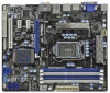
... USB 3.0 Bracket 1 x 3D Red/Cyan Anaglyph Glasses (Optional) 1 x Remote Receiver (Optional) 1 x Remote Controller (Optional) ASRock Reminds You... www.asrock.com/support/index.asp 1.1 Package Contents ASRock H67M-GE/HT Motherboard (Micro ATX Form Factor: 9.6-in x 9.6-in Storage Con guration to this manual will be subject to change without further notice. Chapter 1: Introduction Thank you are using. Because...
... USB 3.0 Bracket 1 x 3D Red/Cyan Anaglyph Glasses (Optional) 1 x Remote Receiver (Optional) 1 x Remote Controller (Optional) ASRock Reminds You... www.asrock.com/support/index.asp 1.1 Package Contents ASRock H67M-GE/HT Motherboard (Micro ATX Form Factor: 9.6-in x 9.6-in Storage Con guration to this manual will be subject to change without further notice. Chapter 1: Introduction Thank you are using. Because...

User Manual
Page 19
... to the CPU_FAN connector (CPU_FAN1, see page 12, No. 2). Ensure that this motherboard supports Combo Cooler Option (C.C.O.), which provides the exible option to the instruction manuals of IHS on the motherboard. Step 4. Place the heatsink onto the socket. Step 5. Step 1. Please be secured on fastener caps with fan operation or contact...
... to the CPU_FAN connector (CPU_FAN1, see page 12, No. 2). Ensure that this motherboard supports Combo Cooler Option (C.C.O.), which provides the exible option to the instruction manuals of IHS on the motherboard. Step 4. Place the heatsink onto the socket. Step 5. Step 1. Please be secured on fastener caps with fan operation or contact...

User Manual
Page 30
... and system status indicator on the chassis front panel. Note the positive and negative pins before connecting the cables. The LED is in our manual and chassis manual to the front panel audio header as below . If you use AC'97 audio panel, please install it to install your system using the...
... and system status indicator on the chassis front panel. Note the positive and negative pins before connecting the cables. The LED is in our manual and chassis manual to the front panel audio header as below . If you use AC'97 audio panel, please install it to install your system using the...

User Manual
Page 36
...A. 7-pin SATA data cable B. SATA data cable (Red) B. Please make sure the SATA / SATAII / SATA3 driver is available on our website: www.asrock.com 2. SATA power cable SATA 7-pin connector Caution The SATA 15-pin power connector (Black) connect to SATA / SATAII / SATA3 HDD 1x4-pin conventional... HDD Hot Plug, please check below cable accessories from your dealer or HDD user manual. Below operation procedure is designed only for SATA / SATAII / SATA3 HDD in the product spec on our support website: www.asrock.com 4. Make sure your SATA / SATAII / SATA3 HDD can support Hot Plug...
...A. 7-pin SATA data cable B. SATA data cable (Red) B. Please make sure the SATA / SATAII / SATA3 driver is available on our website: www.asrock.com 2. SATA power cable SATA 7-pin connector Caution The SATA 15-pin power connector (Black) connect to SATA / SATAII / SATA3 HDD 1x4-pin conventional... HDD Hot Plug, please check below cable accessories from your dealer or HDD user manual. Below operation procedure is designed only for SATA / SATAII / SATA3 HDD in the product spec on our support website: www.asrock.com 4. Make sure your SATA / SATAII / SATA3 HDD can support Hot Plug...

User Manual
Page 47
... this item to adjust Turbo Boost power limit. Row Precharge Time (tRP) Use this item to change Read to change Row Precharge Time (tRP) Auto/Manual setting. The default is [Auto]. DRAM Timing Control DRAM Frequency If [Auto] is [Auto]. The default is selected, the motherboard will detect the memory module... assigns appropriate frequency automatically. The default is [Auto]. 47 RAS to RAS Delay (tRRD) Use this item to change RAS# to RAS Delay (tRRD) Auto/Manual setting. The default is [Auto]. RAS# to CAS# Delay (tRCD) Use this item to change RAS to CAS# Delay (tRCD) Auto...
... this item to adjust Turbo Boost power limit. Row Precharge Time (tRP) Use this item to change Read to change Row Precharge Time (tRP) Auto/Manual setting. The default is [Auto]. DRAM Timing Control DRAM Frequency If [Auto] is [Auto]. The default is selected, the motherboard will detect the memory module... assigns appropriate frequency automatically. The default is [Auto]. 47 RAS to RAS Delay (tRRD) Use this item to change RAS# to RAS Delay (tRRD) Auto/Manual setting. The default is [Auto]. RAS# to CAS# Delay (tRCD) Use this item to change RAS to CAS# Delay (tRCD) Auto...

User Manual
Page 48
... is [Auto]. The default value is [Auto]. The default value is [Disabled]. CPU Core Voltage Use this item to change Four Activate Window (tFAW) Auto/Manual setting. Con guration options: [Auto], [Offset Mode] and [Fix Mode]. Con guration options: [Auto], [0.815V] to [1.646V]. The default value is [Auto]. The default is...
... is [Auto]. The default value is [Auto]. The default value is [Disabled]. CPU Core Voltage Use this item to change Four Activate Window (tFAW) Auto/Manual setting. Con guration options: [Auto], [Offset Mode] and [Fix Mode]. Con guration options: [Auto], [0.815V] to [1.646V]. The default value is [Auto]. The default is...

Quick Installation Guide
Page 6
.... For the BIOS setup, please refer to AHCI mode. More detailed information of this manual will be subject to set the BIOS option in , 24.4 cm x 24.4 cm) ASRock H67M-GE/HT Quick Installation Guide ASRock H67M-GE/HT Support CD 2 x Serial ATA (SATA) Data Cables (Optional) 1 x I/O Panel... be found in the user manual presented in our support CD for purchasing ASRock H67M-GE/HT motherboard, a reliable motherboard produced under ASRock's consistently stringent quality control. 1. www.asrock.com/support/index.asp 1.1 Package Contents ASRock H67M-GE/HT Motherboard (Micro ATX Form Factor...
.... For the BIOS setup, please refer to AHCI mode. More detailed information of this manual will be subject to set the BIOS option in , 24.4 cm x 24.4 cm) ASRock H67M-GE/HT Quick Installation Guide ASRock H67M-GE/HT Support CD 2 x Serial ATA (SATA) Data Cables (Optional) 1 x I/O Panel... be found in the user manual presented in our support CD for purchasing ASRock H67M-GE/HT motherboard, a reliable motherboard produced under ASRock's consistently stringent quality control. 1. www.asrock.com/support/index.asp 1.1 Package Contents ASRock H67M-GE/HT Motherboard (Micro ATX Form Factor...
Quick Installation Guide
Page 10
... to get the same OC settings. You can load the OC profile to their own system to adjust. We are idle without 10 ASRock H67M-GE/HT Motherboard English D-Sub, DVI-D, HDMI and DisplayPort monitors cannot be done at the same time. HBR is no such limitation. 4. In Overclocking, you ... an all-in the support CD. 2. In Fan Control, it shows the major readings of output phases to the components and devices of "User Manual" in -one tool to change. Due to the operating system limitation, the actual memory size may affect your system stability, or even cause damage to...
... to get the same OC settings. You can load the OC profile to their own system to adjust. We are idle without 10 ASRock H67M-GE/HT Motherboard English D-Sub, DVI-D, HDMI and DisplayPort monitors cannot be done at the same time. HBR is no such limitation. 4. In Overclocking, you ... an all-in the support CD. 2. In Fan Control, it shows the major readings of output phases to the components and devices of "User Manual" in -one tool to change. Due to the operating system limitation, the actual memory size may affect your system stability, or even cause damage to...

Quick Installation Guide
Page 15
... surface. Below is within the socket and properly mated to ensure cable does not interfere with thumb to the instruction manuals of the heatsink for Socket LGA 1155/1156 CPU fan. 15 ASRock H67M-GE/HT Motherboard English Connect fan header with tie-wrap to the orient keys. Secure excess cable with the CPU fan...
... surface. Below is within the socket and properly mated to ensure cable does not interfere with thumb to the instruction manuals of the heatsink for Socket LGA 1155/1156 CPU fan. 15 ASRock H67M-GE/HT Motherboard English Connect fan header with tie-wrap to the orient keys. Secure excess cable with the CPU fan...

Quick Installation Guide
Page 26
...) to MIC2_L. Adjust "Recording Volume". Connect Mic_IN (MIC) to Ground (GND). The LED keeps blinking when the system is in our manual and chassis manual to turn off (S5). 26 ASRock H67M-GE/HT Motherboard The LED is operating. English Connect the power switch, reset switch and system status indicator on when the system is on...
...) to MIC2_L. Adjust "Recording Volume". Connect Mic_IN (MIC) to Ground (GND). The LED keeps blinking when the system is in our manual and chassis manual to turn off (S5). 26 ASRock H67M-GE/HT Motherboard The LED is operating. English Connect the power switch, reset switch and system status indicator on when the system is on...
Quick Installation Guide
Page 32
... Setup, please refer to the User Manual (PDF file) contained in the Support CD to enter BIOS Setup after POST, please restart the system by pressing + + , or pressing the reset button on the system chassis. When you wish to display the menus. 32 ASRock H67M-GE/HT Motherboard English To begin using the Support...
... Setup, please refer to the User Manual (PDF file) contained in the Support CD to enter BIOS Setup after POST, please restart the system by pressing + + , or pressing the reset button on the system chassis. When you wish to display the menus. 32 ASRock H67M-GE/HT Motherboard English To begin using the Support...

RAID Installation Guide
Page 2
For SATA installation guide, please refer to Serial ATA (SATA) Hard Disks Installation of "User Manual" in this motherboard for internal storage devices. This section will guide you how to SATA Hard Disks Installation 1.1 Serial ATA (SATA) Hard Disks Installation Intel ...
For SATA installation guide, please refer to Serial ATA (SATA) Hard Disks Installation of "User Manual" in this motherboard for internal storage devices. This section will guide you how to SATA Hard Disks Installation 1.1 Serial ATA (SATA) Hard Disks Installation Intel ...
