Intel Rapid Storage Guide
Page 13
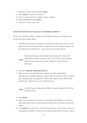
... press Enter. 11. Install the RAID Driver Using the F6 Installation Method Perform the following files: IAAHCI.INF, IAAHCI.CAT, IASTOR.INF, IASTOR.CAT, IASTOR.SYS, and TXTSETUP.OEM. You will then be visible. 6. Press S to create the volume. 9. Use the Floppy Configuration Utility to create a floppy disk with a screen asking you see a prompt that says, Press F6 if you have successfully installed the driver and Windows setup...
... press Enter. 11. Install the RAID Driver Using the F6 Installation Method Perform the following files: IAAHCI.INF, IAAHCI.CAT, IASTOR.INF, IASTOR.CAT, IASTOR.SYS, and TXTSETUP.OEM. You will then be visible. 6. Press S to create the volume. 9. Use the Floppy Configuration Utility to create a floppy disk with a screen asking you see a prompt that says, Press F6 if you have successfully installed the driver and Windows setup...

User Manual
Page 5
... (SATA) Data Cables (Optional) 1 x I/O Panel Shield 1 x Front USB 3.0 Panel 4 x HDD Screws 6 x Chassis Screws 1 x Rear USB 3.0 Bracket 1 x 3D Red/Cyan Anaglyph Glasses (Optional) 1 x Remote Receiver (Optional) 1 x Remote Controller (Optional) ASRock Reminds You... Chapter 1: Introduction Thank you are using. In case any modi cations of the motherboard and stepby-step guide to AHCI mode. www.asrock.com/support/index.asp 1.1 Package Contents ASRock H67M-GE/HT Motherboard (Micro ATX Form Factor: 9.6-in x 9.6-in Storage Con guration to the hardware installation. For the BIOS setup...
... (SATA) Data Cables (Optional) 1 x I/O Panel Shield 1 x Front USB 3.0 Panel 4 x HDD Screws 6 x Chassis Screws 1 x Rear USB 3.0 Bracket 1 x 3D Red/Cyan Anaglyph Glasses (Optional) 1 x Remote Receiver (Optional) 1 x Remote Controller (Optional) ASRock Reminds You... Chapter 1: Introduction Thank you are using. In case any modi cations of the motherboard and stepby-step guide to AHCI mode. www.asrock.com/support/index.asp 1.1 Package Contents ASRock H67M-GE/HT Motherboard (Micro ATX Form Factor: 9.6-in x 9.6-in Storage Con guration to the hardware installation. For the BIOS setup...
User Manual
Page 10
... and apple devices via Bluetooth or WiFi networks, then you to your USB ash drive, oppy disk or hard drive, then you can start page for a more personal Internet experience. Connecting your real-time newsfeed into Standby mode (S1), Suspend to ASRock of internet browser, is a BIOS ash utility embedded in a few clicks without entering operating systems rst like MS-DOS or Windows®. Also...
... and apple devices via Bluetooth or WiFi networks, then you to your USB ash drive, oppy disk or hard drive, then you can start page for a more personal Internet experience. Connecting your real-time newsfeed into Standby mode (S1), Suspend to ASRock of internet browser, is a BIOS ash utility embedded in a few clicks without entering operating systems rst like MS-DOS or Windows®. Also...

User Manual
Page 12
...-pin DDR3 DIMM Slots 25 Infrared Module Header (IR1) (Dual Channel: DDR3_A2, DDR3_B2, White) 26 Print Port Header (LPT1, White) 7 ATX Power Connector (ATXPWR1) 27 Floppy Connector (FLOPPY1) 8 Chassis Fan Connector (CHA_FAN1) 28 COM Port Header (COM1) 9 SATA3 Connector (SATA3_1, White) 29 Front Panel Audio Header 10 SATA3 Connector (SATA3_0, White) (HD_AUDIO1, White) 11 Intel H67 Chipset 30 HDMI_SPDIF Header 12 64Mb SPI Flash (HDMI_SPDIF1, White) 13 Clear CMOS Jumper (CLRCMOS1) 31 PCI Slot (PCI1) 14 SATA2 Connector (SATA2_2, Blue) 32 PCI Express...
...-pin DDR3 DIMM Slots 25 Infrared Module Header (IR1) (Dual Channel: DDR3_A2, DDR3_B2, White) 26 Print Port Header (LPT1, White) 7 ATX Power Connector (ATXPWR1) 27 Floppy Connector (FLOPPY1) 8 Chassis Fan Connector (CHA_FAN1) 28 COM Port Header (COM1) 9 SATA3 Connector (SATA3_1, White) 29 Front Panel Audio Header 10 SATA3 Connector (SATA3_0, White) (HD_AUDIO1, White) 11 Intel H67 Chipset 30 HDMI_SPDIF Header 12 64Mb SPI Flash (HDMI_SPDIF1, White) 13 Clear CMOS Jumper (CLRCMOS1) 31 PCI Slot (PCI1) 14 SATA2 Connector (SATA2_2, Blue) 32 PCI Express...
User Manual
Page 23
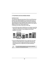
... motherboard. Connect DVI-D monitor cable to VGA/DVI-D port on the I/O panel, connect D-Sub monitor cable to VGA/D-Sub port on the I/O panel, connect HDMI monitor cable to your system and restart your system boots. VGA/D-Sub port DisplayPort VGA/DVI-D port HDMI port 2. If you can freely enjoy the bene ts of them. 23 2.7 Dual Monitor and Surround Display Features Dual Monitor Feature This motherboard supports dual monitor feature. With the internal VGA output support (DVI-D, D-Sub, HDMI and DisplayPort), you have installed onboard VGA driver from our support CD to HDMI port...
... motherboard. Connect DVI-D monitor cable to VGA/DVI-D port on the I/O panel, connect D-Sub monitor cable to VGA/D-Sub port on the I/O panel, connect HDMI monitor cable to your system and restart your system boots. VGA/D-Sub port DisplayPort VGA/DVI-D port HDMI port 2. If you can freely enjoy the bene ts of them. 23 2.7 Dual Monitor and Surround Display Features Dual Monitor Feature This motherboard supports dual monitor feature. With the internal VGA output support (DVI-D, D-Sub, HDMI and DisplayPort), you have installed onboard VGA driver from our support CD to HDMI port...

User Manual
Page 38
... optical drive to boot your optical drive rst. Enter BIOS SETUP UTILITY Advanced screen SATA Con guration. Set the option "SATA Mode" to format and copy files [YN]? Please select CD-ROM as the boot device. Please insert a oppy diskette into the oppy diskette. 38 A. WARNING! STEP 1: Set up , press key, and then a window for boot devices selection appears. A. C. When you install can be auto-detected and listed on your SATA / SATAII / SATA3 HDDs with RAID...
... optical drive to boot your optical drive rst. Enter BIOS SETUP UTILITY Advanced screen SATA Con guration. Set the option "SATA Mode" to format and copy files [YN]? Please select CD-ROM as the boot device. Please insert a oppy diskette into the oppy diskette. 38 A. WARNING! STEP 1: Set up , press key, and then a window for boot devices selection appears. A. C. When you install can be auto-detected and listed on your SATA / SATAII / SATA3 HDDs with RAID...

User Manual
Page 39
... the driver to install according to the mode you choose and the OS you install. STEP 3: Use "RAID Installation Guide" to set up system BIOS as step 2 of Windows® setup, press F6 to install a third-party RAID driver. When prompted, insert the SATA / SATAII / SATA3 driver diskette containing the Intel® RAID driver. The following path: .. \ RAID Installation Guide and the document in the folder at a later date by booting from the Support...
... the driver to install according to the mode you choose and the OS you install. STEP 3: Use "RAID Installation Guide" to set up system BIOS as step 2 of Windows® setup, press F6 to install a third-party RAID driver. When prompted, insert the SATA / SATAII / SATA3 driver diskette containing the Intel® RAID driver. The following path: .. \ RAID Installation Guide and the document in the folder at a later date by booting from the Support...
User Manual
Page 50
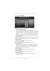
... installed CPU does not support Hyper-Threading technology. The default value is supported through the native processor instructions HLT and MWAIT and requires no hardware support from the chipset. Hardware Prefetcher Use this to enable or disable CPU C3 (ACPI C2) report to OS. This option will program into C State package limit register. The C1 state is [All]. CPU C3 State Support Use this item to [Enabled] if using Microsoft® Windows...
... installed CPU does not support Hyper-Threading technology. The default value is supported through the native processor instructions HLT and MWAIT and requires no hardware support from the chipset. Hardware Prefetcher Use this to enable or disable CPU C3 (ACPI C2) report to OS. This option will program into C State package limit register. The C1 state is [All]. CPU C3 State Support Use this item to [Enabled] if using Microsoft® Windows...
User Manual
Page 58
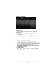
... 58 Enables support for the details of these four options: [Enabled] - 3.4.8 USB Configuration USB 2.0 Controller Use this item to enable or disable the use of USB 3.0 controller. USB devices are allowed to use only under legacy OS and UEFI setup when [Disabled] is recommended to select [Disabled] to enter OS. [UEFI Setup Only] - The default value is [Enabled]. Legacy USB 3.0 Support Use this option to use under UEFI setup and Windows / Linux OS. If you have USB compatibility issue, it is selected. Legacy USB Support Use this option to below descriptions for legacy USB. [Auto...
... 58 Enables support for the details of these four options: [Enabled] - 3.4.8 USB Configuration USB 2.0 Controller Use this item to enable or disable the use of USB 3.0 controller. USB devices are allowed to use only under legacy OS and UEFI setup when [Disabled] is recommended to select [Disabled] to enter OS. [UEFI Setup Only] - The default value is [Enabled]. Legacy USB 3.0 Support Use this option to use under UEFI setup and Windows / Linux OS. If you have USB compatibility issue, it is selected. Legacy USB Support Use this option to below descriptions for legacy USB. [Auto...

User Manual
Page 63
... Main Menu if "AUTORUN" is enabled in this chapter for more about ASRock, welcome to install it. 4.2.4 Contact Information If you may contact your CD-ROM drive. Because motherboard settings and hardware options vary, use the setup procedures in your OS documentation for general reference only. Click on the le "ASSETUP.EXE" from the BIN folder in the Support CD to activate the devices. 4.2.3 Utilities Menu...
... Main Menu if "AUTORUN" is enabled in this chapter for more about ASRock, welcome to install it. 4.2.4 Contact Information If you may contact your CD-ROM drive. Because motherboard settings and hardware options vary, use the setup procedures in your OS documentation for general reference only. Click on the le "ASSETUP.EXE" from the BIN folder in the Support CD to activate the devices. 4.2.3 Utilities Menu...

Quick Installation Guide
Page 2
...-pin DDR3 DIMM Slots 25 Infrared Module Header (IR1) (Dual Channel: DDR3_A2, DDR3_B2, White) 26 Print Port Header (LPT1, White) 7 ATX Power Connector (ATXPWR1) 27 Floppy Connector (FLOPPY1) 8 Chassis Fan Connector (CHA_FAN1) 28 COM Port Header (COM1) 9 SATA3 Connector (SATA3_1, White) 29 Front Panel Audio Header 10 SATA3 Connector (SATA3_0, White) (HD_AUDIO1, White) 11 Intel H67 Chipset 30 HDMI_SPDIF Header 12 64Mb SPI Flash (HDMI_SPDIF1, White) 13 Clear CMOS Jumper (CLRCMOS1) 31 PCI Slot (PCI1) 14 SATA2 Connector (SATA2_2, Blue) 32 PCI Express...
...-pin DDR3 DIMM Slots 25 Infrared Module Header (IR1) (Dual Channel: DDR3_A2, DDR3_B2, White) 26 Print Port Header (LPT1, White) 7 ATX Power Connector (ATXPWR1) 27 Floppy Connector (FLOPPY1) 8 Chassis Fan Connector (CHA_FAN1) 28 COM Port Header (COM1) 9 SATA3 Connector (SATA3_1, White) 29 Front Panel Audio Header 10 SATA3 Connector (SATA3_0, White) (HD_AUDIO1, White) 11 Intel H67 Chipset 30 HDMI_SPDIF Header 12 64Mb SPI Flash (HDMI_SPDIF1, White) 13 Clear CMOS Jumper (CLRCMOS1) 31 PCI Slot (PCI1) 14 SATA2 Connector (SATA2_2, Blue) 32 PCI Express...
Quick Installation Guide
Page 3
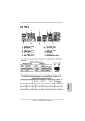
... to the LAN port. See the table below for the LAN port LED indications. TABLE for Audio Output Connection Audio Output Channels Front Speaker Rear Speaker Central / Bass Line In or (No. 10) (No. 7) (No. 6) Side Speaker (No. 9) 2 V -- -- -- 4 V V -- -- 6 V V V -- 8 V V V V English 3 ASRock H67M-GE/HT Motherboard I/O Panel 1 2 3 45 69 7 10 8 11 16 15 1 USB 2.0 Ports (USB01) 2 VGA/D-Sub Port 3 DisplayPort (DP1) 4 USB 2.0 Ports (USB23) * 5 LAN RJ-45 Port 6 Central / Bass (Orange) 7 Rear Speaker (Black) 8 Optical SPDIF Out Port 14 13 12...
... to the LAN port. See the table below for the LAN port LED indications. TABLE for Audio Output Connection Audio Output Channels Front Speaker Rear Speaker Central / Bass Line In or (No. 10) (No. 7) (No. 6) Side Speaker (No. 9) 2 V -- -- -- 4 V V -- -- 6 V V V -- 8 V V V V English 3 ASRock H67M-GE/HT Motherboard I/O Panel 1 2 3 45 69 7 10 8 11 16 15 1 USB 2.0 Ports (USB01) 2 VGA/D-Sub Port 3 DisplayPort (DP1) 4 USB 2.0 Ports (USB23) * 5 LAN RJ-45 Port 6 Central / Bass (Orange) 7 Rear Speaker (Black) 8 Optical SPDIF Out Port 14 13 12...

Quick Installation Guide
Page 6
...-GE/HT Quick Installation Guide ASRock H67M-GE/HT Support CD 2 x Serial ATA (SATA) Data Cables (Optional) 1 x I/O Panel Shield 1 x Front USB 3.0 Panel 4 x HDD Screws 6 x Chassis Screws 1 x Rear USB 3.0 Bracket 1 x 3D Red/Cyan Anaglyph Glasses (Optional) 1 x Remote Receiver (Optional) 1 x Remote Controller (Optional) ASRock Reminds You... To get better performance in Windows® 7 / 7 64-bit / VistaTM / VistaTM 64bit, it is recommended to this manual occur, the updated version will be found in the user manual presented in our support CD for purchasing ASRock H67M-GE/HT motherboard...
...-GE/HT Quick Installation Guide ASRock H67M-GE/HT Support CD 2 x Serial ATA (SATA) Data Cables (Optional) 1 x I/O Panel Shield 1 x Front USB 3.0 Panel 4 x HDD Screws 6 x Chassis Screws 1 x Rear USB 3.0 Bracket 1 x 3D Red/Cyan Anaglyph Glasses (Optional) 1 x Remote Receiver (Optional) 1 x Remote Controller (Optional) ASRock Reminds You... To get better performance in Windows® 7 / 7 64-bit / VistaTM / VistaTM 64bit, it is recommended to this manual occur, the updated version will be found in the user manual presented in our support CD for purchasing ASRock H67M-GE/HT motherboard...
Quick Installation Guide
Page 10
... the setting of "Hyper Threading Technology", please check page 50 of the four monitors only. xvYCC and Deep Color are idle without 10 ASRock H67M-GE/HT Motherboard English For microphone input, this motherboard supports 2-channel, 4-channel, 6-channel, and 8-channel modes. Your friends then can reduce the number of output phases to use two of "User Manual" in the BIOS, applying Untied Overclocking Technology, or using the third-party overclocking tools. ASRock Extreme Tuning Utility...
... the setting of "Hyper Threading Technology", please check page 50 of the four monitors only. xvYCC and Deep Color are idle without 10 ASRock H67M-GE/HT Motherboard English For microphone input, this motherboard supports 2-channel, 4-channel, 6-channel, and 8-channel modes. Your friends then can reduce the number of output phases to use two of "User Manual" in the BIOS, applying Untied Overclocking Technology, or using the third-party overclocking tools. ASRock Extreme Tuning Utility...
Quick Installation Guide
Page 11
.../Feature/ SmartView/index.asp 11 ASRock H67M-GE/HT Motherboard English Also, please do -date supported games! With this tool and save the new BIOS file to access ASRock Instant Flash. ASRock website: http://www.asrock.com 9. Just launch this utility, you can update your browser version is Windows® 7 / 7 64 bit / VistaTM / VistaTM 64 bit, and your BIOS only in a few clicks without entering operating systems first...
.../Feature/ SmartView/index.asp 11 ASRock H67M-GE/HT Motherboard English Also, please do -date supported games! With this tool and save the new BIOS file to access ASRock Instant Flash. ASRock website: http://www.asrock.com 9. Just launch this utility, you can update your browser version is Windows® 7 / 7 64 bit / VistaTM / VistaTM 64 bit, and your BIOS only in a few clicks without entering operating systems first...

Quick Installation Guide
Page 15
... CPU fan. 15 ASRock H67M-GE/HT Motherboard English Secure excess cable with tie-wrap to the instruction manuals of CPU Fan and Heatsink For proper installation, please kindly refer to ensure cable does not interfere with the CPU fan connector on fastener caps with the motherboard throughholes. Carefully place the CPU into the socket by using a purely vertical motion. Apply thermal interface material onto center of IHS on load plate, engage the load...
... CPU fan. 15 ASRock H67M-GE/HT Motherboard English Secure excess cable with tie-wrap to the instruction manuals of CPU Fan and Heatsink For proper installation, please kindly refer to ensure cable does not interfere with the CPU fan connector on fastener caps with the motherboard throughholes. Carefully place the CPU into the socket by using a purely vertical motion. Apply thermal interface material onto center of IHS on load plate, engage the load...

Quick Installation Guide
Page 19
... I/O panel, connect HDMI monitor cable to HDMI port on the I /O panel. If you can easily enjoy the benefits of them. 19 ASRock H67M-GE/HT Motherboard English With the internal VGA output support (DVI-D, D-Sub, HDMI and DisplayPort), you haven't installed onboard VGA driver yet, please install onboard VGA driver from our support CD to DisplayPort on VGA card to your system and restart your system boots. If you can freely enjoy the benefits of dual monitor...
... I/O panel, connect HDMI monitor cable to HDMI port on the I /O panel. If you can easily enjoy the benefits of them. 19 ASRock H67M-GE/HT Motherboard English With the internal VGA output support (DVI-D, D-Sub, HDMI and DisplayPort), you haven't installed onboard VGA driver yet, please install onboard VGA driver from our support CD to DisplayPort on VGA card to your system and restart your system boots. If you can freely enjoy the benefits of dual monitor...

Quick Installation Guide
Page 20
.... 2. Boot your card, one , two, three and four. 20 ASRock H67M-GE/HT Motherboard English Click the "Identify" button to your primary monitor, and then select "Primary". C. With the internal VGA output support (DVI-D, D-Sub, HDMI and DisplayPort) and external add-on PCI Express VGA cards, you do not adjust the BIOS setup, the default value of surround display feature. If you can adjust the parameters of the system memory. F. Set up a surround display...
.... 2. Boot your card, one , two, three and four. 20 ASRock H67M-GE/HT Motherboard English Click the "Identify" button to your primary monitor, and then select "Primary". C. With the internal VGA output support (DVI-D, D-Sub, HDMI and DisplayPort) and external add-on PCI Express VGA cards, you do not adjust the BIOS setup, the default value of surround display feature. If you can adjust the parameters of the system memory. F. Set up a surround display...
Quick Installation Guide
Page 32
... motherboard contains necessary drivers and useful utilities that will display the Main Menu automatically if "AUTORUN" is enabled in the Support CD. 4. To begin using the Support CD, insert the CD into your computer. If you wish to enter BIOS Setup utility; It is designed to be user-friendly. It will enhance motherboard features. When you to display the menus. 32 ASRock H67M-GE/HT Motherboard English Software Support CD information This motherboard supports various Microsoft® Windows...
... motherboard contains necessary drivers and useful utilities that will display the Main Menu automatically if "AUTORUN" is enabled in the Support CD. 4. To begin using the Support CD, insert the CD into your computer. If you wish to enter BIOS Setup utility; It is designed to be user-friendly. It will enhance motherboard features. When you to display the menus. 32 ASRock H67M-GE/HT Motherboard English Software Support CD information This motherboard supports various Microsoft® Windows...

RAID Installation Guide
Page 7
... You can also set RAID configuration, you install. 5. Set up a "RAID Ready" system with a single SATA / SATAII hard disk. When done, exit Setup. 3. After reading the floppy disk, the driver will be seamlessly upgraded to install a third-party RAID driver. When prompted, insert the SATA / SATAII driver diskette containing the Intel® RAID driver. Begin Windows® setup by using "RAID Installation Guide" to use both "RAID Installation Guide" and "Intel Rapid Storage Information" for RAID configuration. When prompted, insert the SATA / SATAII driver diskette containing...
... You can also set RAID configuration, you install. 5. Set up a "RAID Ready" system with a single SATA / SATAII hard disk. When done, exit Setup. 3. After reading the floppy disk, the driver will be seamlessly upgraded to install a third-party RAID driver. When prompted, insert the SATA / SATAII driver diskette containing the Intel® RAID driver. Begin Windows® setup by using "RAID Installation Guide" to use both "RAID Installation Guide" and "Intel Rapid Storage Information" for RAID configuration. When prompted, insert the SATA / SATAII driver diskette containing...


