
User Manual
Page 11
... supply manufacturer for the completed system. According to de ne the power consumption for more details. 11 According to adopt three different CPU cooler types, Socket LGA 775, LGA 1155 and LGA 1156.
... supply manufacturer for the completed system. According to de ne the power consumption for more details. 11 According to adopt three different CPU cooler types, Socket LGA 775, LGA 1155 and LGA 1156.

User Manual
Page 12
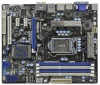
... T: USB4 Top: B: USB5 RJ-45 CHA_FAN1 CHA_FAN2 LAN PHY 8 Top: CTR BASS Center: REAR SPK Bottom: Optical SPDIF SATA3_1 SATA3_0 CMOS H67M-GE/HT Battery 9 Top: LINE IN Center: FRONT Bottom: MIC IN USB 3.0 34 PCIE1 10 33 DX10.1 PCI Express 2.0 ErP/EuP Ready Super ...PLED1) 2 CPU Fan Connector (CPU_FAN1) 21 USB 2.0 Header (USB8_9, Blue) 3 ATX 12V Power Connector (ATX12V1) 22 USB 2.0 Header (USB10_11, Blue) 4 1155-Pin CPU Socket 23 USB 2.0 Header (USB6_7, Blue) 5 2 x 240-pin DDR3 DIMM Slots 24 Consumer Infrared Module Header (Dual Channel: DDR3_A1, DDR3_B1, Blue) (CIR1) 6...
... T: USB4 Top: B: USB5 RJ-45 CHA_FAN1 CHA_FAN2 LAN PHY 8 Top: CTR BASS Center: REAR SPK Bottom: Optical SPDIF SATA3_1 SATA3_0 CMOS H67M-GE/HT Battery 9 Top: LINE IN Center: FRONT Bottom: MIC IN USB 3.0 34 PCIE1 10 33 DX10.1 PCI Express 2.0 ErP/EuP Ready Super ...PLED1) 2 CPU Fan Connector (CPU_FAN1) 21 USB 2.0 Header (USB8_9, Blue) 3 ATX 12V Power Connector (ATX12V1) 22 USB 2.0 Header (USB10_11, Blue) 4 1155-Pin CPU Socket 23 USB 2.0 Header (USB6_7, Blue) 5 2 x 240-pin DDR3 DIMM Slots 24 Consumer Infrared Module Header (Dual Channel: DDR3_A1, DDR3_B1, Blue) (CIR1) 6...

User Manual
Page 17
...Place Cap). 1. Rotate the load plate to clear retention tab. Load Plate Load Lever Contact Array Socket Body 1155-Pin Socket Overview Before you insert the 1155-Pin CPU into the socket if above situation is recommended to use the cap tab to fully open position at approximately 135 ...degrees. Step 1. Disengaging the lever by depressing down and out on the socket. 2.3 CPU Installation For the installation of Intel 1155-Pin CPU, please follow the steps below. Rotate the load lever to handle and avoid kicking off the PnP...
...Place Cap). 1. Rotate the load plate to clear retention tab. Load Plate Load Lever Contact Array Socket Body 1155-Pin Socket Overview Before you insert the 1155-Pin CPU into the socket if above situation is recommended to use the cap tab to fully open position at approximately 135 ...degrees. Step 1. Disengaging the lever by depressing down and out on the socket. 2.3 CPU Installation For the installation of Intel 1155-Pin CPU, please follow the steps below. Rotate the load lever to handle and avoid kicking off the PnP...

User Manual
Page 18
... the IHS. Step 3-3. Step 4-2. Insert the 1155-Pin CPU: Step 3-1. Hold the CPU by using a purely vertical motion. black line Step 3-2. Locate Pin1 and the two orientation key notches. orientation key notch alignment key Pin1 Pin1 orientation key notch 1155-Pin CPU alignment key 1155-Pin Socket For proper inserting, please ensure to the...
... the IHS. Step 3-3. Step 4-2. Insert the 1155-Pin CPU: Step 3-1. Hold the CPU by using a purely vertical motion. black line Step 3-2. Locate Pin1 and the two orientation key notches. orientation key notch alignment key Pin1 Pin1 orientation key notch 1155-Pin CPU alignment key 1155-Pin Socket For proper inserting, please ensure to the...

User Manual
Page 19
... Repeat with the motherboard throughholes. Ensure fan cables are oriented on side closest to the instruction manuals of the heatsink for Socket LGA 1155/1156 CPU fan. 19 Align fasteners with remaining fasteners. Connect fan header with each other components. The white throughholes are ...Places) If you need to spray thermal interface material between the CPU and the heatsink to ensure cable does not interfere with 1155-Pin socket that this motherboard supports Combo Cooler Option (C.C.O.), which provides the exible option to install and lock. Step 6. Secure excess ...
... Repeat with the motherboard throughholes. Ensure fan cables are oriented on side closest to the instruction manuals of the heatsink for Socket LGA 1155/1156 CPU fan. 19 Align fasteners with remaining fasteners. Connect fan header with each other components. The white throughholes are ...Places) If you need to spray thermal interface material between the CPU and the heatsink to ensure cable does not interfere with 1155-Pin socket that this motherboard supports Combo Cooler Option (C.C.O.), which provides the exible option to install and lock. Step 6. Secure excess ...

Quick Installation Guide
Page 2
... RJ-45 CHA_FAN1 CHA_FAN2 LAN PHY 8 Top: CTR BASS Center: REAR SPK Bottom: Optical SPDIF SATA3_1 SATA3_0 CMOS H67M-GE/HT Battery 9 Top: LINE IN Center: FRONT Bottom: MIC IN USB 3.0 34 PCIE1 10 33 DX10.1 PCI Express... (CPU_FAN1) 21 USB 2.0 Header (USB8_9, Blue) 3 ATX 12V Power Connector (ATX12V1) 22 USB 2.0 Header (USB10_11, Blue) 4 1155-Pin CPU Socket 23 USB 2.0 Header (USB6_7, Blue) 5 2 x 240-pin DDR3 DIMM Slots 24 Consumer Infrared Module Header (Dual Channel: DDR3_A1, ... (SPEAKER 1, White) 19 USB 3.0 Header (USB_12_13, Light Blue) 2 ASRock H67M-GE/HT Motherboard English
... RJ-45 CHA_FAN1 CHA_FAN2 LAN PHY 8 Top: CTR BASS Center: REAR SPK Bottom: Optical SPDIF SATA3_1 SATA3_0 CMOS H67M-GE/HT Battery 9 Top: LINE IN Center: FRONT Bottom: MIC IN USB 3.0 34 PCIE1 10 33 DX10.1 PCI Express... (CPU_FAN1) 21 USB 2.0 Header (USB8_9, Blue) 3 ATX 12V Power Connector (ATX12V1) 22 USB 2.0 Header (USB10_11, Blue) 4 1155-Pin CPU Socket 23 USB 2.0 Header (USB6_7, Blue) 5 2 x 240-pin DDR3 DIMM Slots 24 Consumer Infrared Module Header (Dual Channel: DDR3_A1, ... (SPEAKER 1, White) 19 USB 3.0 Header (USB_12_13, Light Blue) 2 ASRock H67M-GE/HT Motherboard English

Quick Installation Guide
Page 12
... the completed system shall be used. 15. According to adopt three different CPU cooler types, Socket LGA 775, LGA 1155 and LGA 1156. Before you install the PC system. 14. EuP, stands for more details. 12 ASRock H67M-GE/HT Motherboard English Please be noticed that not all the 775 and 1156 CPU Fan can be...
... the completed system shall be used. 15. According to adopt three different CPU cooler types, Socket LGA 775, LGA 1155 and LGA 1156. Before you install the PC system. 14. EuP, stands for more details. 12 ASRock H67M-GE/HT Motherboard English Please be noticed that not all the 775 and 1156 CPU Fan can be...

Quick Installation Guide
Page 13
... CPU, please follow the steps below. Unplug the power cord from the wall socket before you insert the 1155-Pin CPU into the socket, please check if the CPU surface is unclean or if there is found. To...the CPU into the screw holes to do not touch the ICs. 4. Load Plate Contact Array Load Lever Socket Body 1155-Pin Socket Overview Before you install motherboard components or change any component, place it on a grounded antstatic pad or in ... settings. 1. Otherwise, the CPU will be seriously damaged. Whenever you handle components. 3. English 13 ASRock H67M-GE/HT Motherboard
... CPU, please follow the steps below. Unplug the power cord from the wall socket before you insert the 1155-Pin CPU into the socket, please check if the CPU surface is unclean or if there is found. To...the CPU into the screw holes to do not touch the ICs. 4. Load Plate Contact Array Load Lever Socket Body 1155-Pin Socket Overview Before you install motherboard components or change any component, place it on a grounded antstatic pad or in ... settings. 1. Otherwise, the CPU will be seriously damaged. Whenever you handle components. 3. English 13 ASRock H67M-GE/HT Motherboard

Quick Installation Guide
Page 14
Insert the 1155-Pin CPU: Step 3-1. Step 3-2. Step 1-2. Rotate the load plate to fully open position at approximately 100 degrees. Rotate the load lever to match the two orientation key notches of the socket. 14 ASRock H67M-GE/HT Motherboard Hold the CPU by depressing down and out ...on the hook to handle and avoid kicking off the PnP cap. 2. orientation key notch alignment key Pin1 Pin1 orientation key notch 1155-Pin CPU alignment key 1155-Pin Socket For proper inserting...
Insert the 1155-Pin CPU: Step 3-1. Step 3-2. Step 1-2. Rotate the load plate to fully open position at approximately 100 degrees. Rotate the load lever to match the two orientation key notches of the socket. 14 ASRock H67M-GE/HT Motherboard Hold the CPU by depressing down and out ...on the hook to handle and avoid kicking off the PnP cap. 2. orientation key notch alignment key Pin1 Pin1 orientation key notch 1155-Pin CPU alignment key 1155-Pin Socket For proper inserting...

Quick Installation Guide
Page 15
... without rotating them clockwise, the heatsink cannot be noticed that the CPU is an example to the instruction manuals of the heatsink for Socket LGA 1155/1156 CPU fan. 15 ASRock H67M-GE/HT Motherboard English Fan cables on side closest to MB header Fastener slots pointing straight out Press Down (4 Places) If you press down...
... without rotating them clockwise, the heatsink cannot be noticed that the CPU is an example to the instruction manuals of the heatsink for Socket LGA 1155/1156 CPU fan. 15 ASRock H67M-GE/HT Motherboard English Fan cables on side closest to MB header Fastener slots pointing straight out Press Down (4 Places) If you press down...

Quick Installation Guide
Page 186
EuP 2 1 2 3 IC 4 5 2.1 CPU 설치 Intel 1155 핀 CPU 장착판 Load Plate Load Lever Contact Array Socket Body 1155 1155 핀 CPU CPU CPU CPU 한 국 어 186 ASRock H67M-GE/HT Motherboard
EuP 2 1 2 3 IC 4 5 2.1 CPU 설치 Intel 1155 핀 CPU 장착판 Load Plate Load Lever Contact Array Socket Body 1155 1155 핀 CPU CPU CPU CPU 한 국 어 186 ASRock H67M-GE/HT Motherboard

Quick Installation Guide
Page 210
1. 2. 3. IC 4. 2.1 CPU Intel 1155-LAND CPU Load Plate Load Lever Contact Array Socket Body 1155 1155-LAND CPU CPU CPU CPU 1 1-1 日本語 210 ASRock H67M-GE/HT Motherboard
1. 2. 3. IC 4. 2.1 CPU Intel 1155-LAND CPU Load Plate Load Lever Contact Array Socket Body 1155 1155-LAND CPU CPU CPU CPU 1 1-1 日本語 210 ASRock H67M-GE/HT Motherboard

Quick Installation Guide
Page 212
4 4-1 HIS 4-2 4-3 2.2 CPU CPU 以下は、1155-LAND CPU 1 HIS Apply Thermal Interface Material 2 CPU_FAN1、2 No. 2 CPU 3 4 Fan cables on side closest to MB header Fastener slots pointing straight out Press Down (4 Places) 5 CPU 6 C.C.O Socket LGA 775、LGA 1155 と LGA 1156 の 3 CPU Socket LGA 1155/1156 CPU 日本語 212 ASRock H67M-GE/HT Motherboard
4 4-1 HIS 4-2 4-3 2.2 CPU CPU 以下は、1155-LAND CPU 1 HIS Apply Thermal Interface Material 2 CPU_FAN1、2 No. 2 CPU 3 4 Fan cables on side closest to MB header Fastener slots pointing straight out Press Down (4 Places) 5 CPU 6 C.C.O Socket LGA 775、LGA 1155 と LGA 1156 の 3 CPU Socket LGA 1155/1156 CPU 日本語 212 ASRock H67M-GE/HT Motherboard

Quick Installation Guide
Page 232
2 安全防范 1 2 3 4 5 2.1 CPU 安裝 要安裝 Intel 1155 針 CPU Load Plate Contact Array Load Lever Socket Body 1155 在您將 1155 針 CPU CPU CPU CPU 步驟 1. 1-1 簡體中文 232 ASRock H67M-GE/HT Motherboard
2 安全防范 1 2 3 4 5 2.1 CPU 安裝 要安裝 Intel 1155 針 CPU Load Plate Contact Array Load Lever Socket Body 1155 在您將 1155 針 CPU CPU CPU CPU 步驟 1. 1-1 簡體中文 232 ASRock H67M-GE/HT Motherboard

Quick Installation Guide
Page 255
2 安全防範 1 2 3 4 5 2.1 CPU 安裝 要安裝 Intel 1155 針 CPU Load Plate Contact Array Load Lever Socket Body ( 插槽 ) 1155 在您將 1155 針 CPU CPU CPU CPU 步驟 1. 1-1 繁體中文 255 ASRock H67M-GE/HT Motherboard
2 安全防範 1 2 3 4 5 2.1 CPU 安裝 要安裝 Intel 1155 針 CPU Load Plate Contact Array Load Lever Socket Body ( 插槽 ) 1155 在您將 1155 針 CPU CPU CPU CPU 步驟 1. 1-1 繁體中文 255 ASRock H67M-GE/HT Motherboard