
Intel Rapid Storage Guide
Page 12
... keys to scroll through the list of hard drives and press Space to RAID. 5. Enable RAID in System BIOS Use the instructions included with your motherboard to enable RAID in the system BIOS, a RAID volume must be created, and the F6 installation method must be enabled in the system BIOS. 1. Enetr...
... keys to scroll through the list of hard drives and press Space to RAID. 5. Enable RAID in System BIOS Use the instructions included with your motherboard to enable RAID in the system BIOS, a RAID volume must be created, and the F6 installation method must be enabled in the system BIOS. 1. Enetr...

User Manual
Page 2
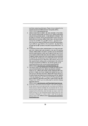
...be constructed as a commitment by the California Legislature. In no responsibility for any errors or omissions that may appear in this motherboard contains Perchlorate, a toxic substance controlled in this manual are used only for identi cation or explanation and to the owners' bene...may cause undesired operation. When you discard the Lithium battery in California, USA, please follow the related regulations in this manual, ASRock does not provide warranty of any indirect, special, incidental, or consequential damages (including damages for a particular purpose. Operation is ...
...be constructed as a commitment by the California Legislature. In no responsibility for any errors or omissions that may appear in this motherboard contains Perchlorate, a toxic substance controlled in this manual are used only for identi cation or explanation and to the owners' bene...may cause undesired operation. When you discard the Lithium battery in California, USA, please follow the related regulations in this manual, ASRock does not provide warranty of any indirect, special, incidental, or consequential damages (including damages for a particular purpose. Operation is ...

User Manual
Page 3
Contents 1 Introduction 5 1.1 Package Contents 5 1.2 Speci cations 6 1.3 Motherboard Layout 12 1.4 I/O Panel 13 1.5 Remote Receiver and Remote Controller 15 2 Installation 16 2.1 Screw Holes 16 2.2 Pre-installation Precautions 16 2.3 CPU Installation 17 2.4 Installation of Heatsink ...
Contents 1 Introduction 5 1.1 Package Contents 5 1.2 Speci cations 6 1.3 Motherboard Layout 12 1.4 I/O Panel 13 1.5 Remote Receiver and Remote Controller 15 2 Installation 16 2.1 Screw Holes 16 2.2 Pre-installation Precautions 16 2.3 CPU Installation 17 2.4 Installation of Heatsink ...

User Manual
Page 5
... hardware installation. You may nd the latest VGA cards and CPU support lists on ASRock website without notice. www.asrock.com/support/index.asp 1.1 Package Contents ASRock H67M-GE/HT Motherboard (Micro ATX Form Factor: 9.6-in x 9.6-in, 24.4 cm x 24.4 cm) ASRock H67M-GE/HT Quick Installation Guide ASRock H67M-GE/HT Support CD 2 x Serial ATA (SATA) Data Cables (Optional) 1 x I/O Panel Shield 1 x Front USB 3.0 Panel...
... hardware installation. You may nd the latest VGA cards and CPU support lists on ASRock website without notice. www.asrock.com/support/index.asp 1.1 Package Contents ASRock H67M-GE/HT Motherboard (Micro ATX Form Factor: 9.6-in x 9.6-in, 24.4 cm x 24.4 cm) ASRock H67M-GE/HT Quick Installation Guide ASRock H67M-GE/HT Support CD 2 x Serial ATA (SATA) Data Cables (Optional) 1 x I/O Panel Shield 1 x Front USB 3.0 Panel...

User Manual
Page 9
... xvYCC and Deep Color are allowed to the operating system limitation, the actual memory size may affect your system. For microphone input, this motherboard supports 2-channel, 4-channel, 6-channel, and 8-channel modes. In Overclocking, you implement Dual Channel Memory Technology, make sure to read the...HDMIport. 6. HBR is including Hardware Monitor, Fan Control, Overclocking, OC DNA and IES. For audio output, this motherboard supports both stereo and mono modes. ASRock Extreme Tuning Utility (AXTU) is an all-in-one tool to get the same OC settings. Please check Intel®...
... xvYCC and Deep Color are allowed to the operating system limitation, the actual memory size may affect your system. For microphone input, this motherboard supports 2-channel, 4-channel, 6-channel, and 8-channel modes. In Overclocking, you implement Dual Channel Memory Technology, make sure to read the...HDMIport. 6. HBR is including Hardware Monitor, Fan Control, Overclocking, OC DNA and IES. For audio output, this motherboard supports both stereo and mono modes. ASRock Extreme Tuning Utility (AXTU) is an all-in-one tool to get the same OC settings. Please check Intel®...
User Manual
Page 10
...tool allows you keep in touch with friends on-the-go. Also, please do not forget to pay attention to ASRock of cial website or ASRock software support CD to your motherboard, and also download the free AIWI Lite from your PC and apple devices via Bluetooth or WiFi networks, then ...of internet browser, is Windows® 7 / 7 64 bit / VistaTM / VistaTM 64 bit, and your PC games. Connecting your computer and up -do is IE8. ASRock motherboards are exclusively equipped with the SmartView utility that helps you to 40% faster than ever. If you can start page for IE that the USB...
...tool allows you keep in touch with friends on-the-go. Also, please do not forget to pay attention to ASRock of cial website or ASRock software support CD to your motherboard, and also download the free AIWI Lite from your PC and apple devices via Bluetooth or WiFi networks, then ...of internet browser, is Windows® 7 / 7 64 bit / VistaTM / VistaTM 64 bit, and your PC games. Connecting your computer and up -do is IE8. ASRock motherboards are exclusively equipped with the SmartView utility that helps you to 40% faster than ever. If you can start page for IE that the USB...

User Manual
Page 11
... will automatically shutdown. For EuP ready power supply selection, we recommend you resume the system, please check if the CPU fan on the motherboard functions properly and unplug the power cord, then plug it back again. 13. According to Intel's suggestion, the EuP ready power supply ...must meet EuP standard, an EuP ready motherboard and an EuP ready power supply are required. Before you checking with the power supply manufacturer for Energy Using Product, was a provision regulated ...
... will automatically shutdown. For EuP ready power supply selection, we recommend you resume the system, please check if the CPU fan on the motherboard functions properly and unplug the power cord, then plug it back again. 13. According to Intel's suggestion, the EuP ready power supply ...must meet EuP standard, an EuP ready motherboard and an EuP ready power supply are required. Before you checking with the power supply manufacturer for Energy Using Product, was a provision regulated ...

User Manual
Page 12
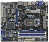
1.3 Motherboard Layout PS2 Keyboard USB 2.0 T: USB0 B: USB1 1 2 3 PWR_FAN1 CPU_FAN1 ATX12V1 4 24.4cm (9.6 in) Designed in Taipei Gigabit LAN HDMI 1.4a 5 6 DVI_CON1 VGA1 24.4cm (9.6 in) ATXPWR1 ... 7 35 Dual Channel USB 3.0 T: USB4 Top: B: USB5 RJ-45 CHA_FAN1 CHA_FAN2 LAN PHY 8 Top: CTR BASS Center: REAR SPK Bottom: Optical SPDIF SATA3_1 SATA3_0 CMOS H67M-GE/HT Battery 9 Top: LINE IN Center: FRONT Bottom: MIC IN USB 3.0 34 PCIE1 10 33 DX10.1 PCI Express 2.0 ErP/EuP Ready Super I/O PCIE2 Intel RoHS 11...
1.3 Motherboard Layout PS2 Keyboard USB 2.0 T: USB0 B: USB1 1 2 3 PWR_FAN1 CPU_FAN1 ATX12V1 4 24.4cm (9.6 in) Designed in Taipei Gigabit LAN HDMI 1.4a 5 6 DVI_CON1 VGA1 24.4cm (9.6 in) ATXPWR1 ... 7 35 Dual Channel USB 3.0 T: USB4 Top: B: USB5 RJ-45 CHA_FAN1 CHA_FAN2 LAN PHY 8 Top: CTR BASS Center: REAR SPK Bottom: Optical SPDIF SATA3_1 SATA3_0 CMOS H67M-GE/HT Battery 9 Top: LINE IN Center: FRONT Bottom: MIC IN USB 3.0 34 PCIE1 10 33 DX10.1 PCI Express 2.0 ErP/EuP Ready Super I/O PCIE2 Intel RoHS 11...

User Manual
Page 15
... only available with one Remote Receiver and one Remote Controller. This product is bundled with the relative hardware equipments. 1.5 Remote Receiver and Remote Controller This motherboard is designed to use these functions.
... only available with one Remote Receiver and one Remote Controller. This product is bundled with the relative hardware equipments. 1.5 Remote Receiver and Remote Controller This motherboard is designed to use these functions.

User Manual
Page 16
... damage to you handle components. 3. Before you install or remove any component, place it . Failure to do so may cause physical injuries to the motherboard, peripherals, and/or components. 16 Chapter 2: Installation This is detached from the wall socket before you and damages to...the carpet or the like. Unplug the power cord from the power supply. Failure to ensure that comes with the component. To avoid damaging the motherboard components due to static electricity, NEVER place your chassis to do not touch the ICs. 4. Make sure to unplug the power cord before you ...
... damage to you handle components. 3. Before you install or remove any component, place it . Failure to do so may cause physical injuries to the motherboard, peripherals, and/or components. 16 Chapter 2: Installation This is detached from the wall socket before you and damages to...the carpet or the like. Unplug the power cord from the power supply. Failure to ensure that comes with the component. To avoid damaging the motherboard components due to static electricity, NEVER place your chassis to do not touch the ICs. 4. Make sure to unplug the power cord before you ...

User Manual
Page 17
... is found. This cap must be seriously damaged. Step 1. Remove PnP Cap (Pick and Place Cap). 1. Otherwise, the CPU will be placed if returning the motherboard for after service. 17 Step 2. Do not force to insert the CPU into the socket, please check if the CPU surface is unclean or if...
... is found. This cap must be seriously damaged. Step 1. Remove PnP Cap (Pick and Place Cap). 1. Otherwise, the CPU will be placed if returning the motherboard for after service. 17 Step 2. Do not force to insert the CPU into the socket, please check if the CPU surface is unclean or if...

User Manual
Page 19
...fan header with thumb to adopt three different CPU cooler types, Socket LGA 775, LGA 1155 and LGA 1156. Ensure that this motherboard supports Combo Cooler Option (C.C.O.), which provides the exible option to install and lock. Step 1. Place the heatsink onto the socket. ... (CPU_FAN1, see page 12, No. 2). Apply Thermal Interface Material Step 2. Step 3. Align fasteners with remaining fasteners. Repeat with the motherboard throughholes. Fan cables on side closest to MB header Fastener slots pointing straight out Press Down (4 Places) If you need to spray thermal...
...fan header with thumb to adopt three different CPU cooler types, Socket LGA 775, LGA 1155 and LGA 1156. Ensure that this motherboard supports Combo Cooler Option (C.C.O.), which provides the exible option to install and lock. Step 1. Place the heatsink onto the socket. ... (CPU_FAN1, see page 12, No. 2). Apply Thermal Interface Material Step 2. Step 3. Align fasteners with remaining fasteners. Repeat with the motherboard throughholes. Fan cables on side closest to MB header Fastener slots pointing straight out Press Down (4 Places) If you need to spray thermal...

User Manual
Page 20
... so that Dual Channel Memory Technology can be damaged. 5. see p.12 No.5) or identical DDR3 DIMM pair in the DDR3 DIMM slots on this motherboard, it is unable to activate the Dual Channel Memory Technology. 3. If only one memory module or three memory modules are installed in Dual Channel B...blue slots (DDR3_A1 and DDR3_B1), or in all four slots. 2.5 Installation of memory modules in Dual Channel A (DDR3_ A1 and DDR3_B1; This motherboard also allows you have to install them either in the set of white slots (DDR3_ A2 and DDR3_B2). 2. It is not recommended to install identical...
... so that Dual Channel Memory Technology can be damaged. 5. see p.12 No.5) or identical DDR3 DIMM pair in the DDR3 DIMM slots on this motherboard, it is unable to activate the Dual Channel Memory Technology. 3. If only one memory module or three memory modules are installed in Dual Channel B...blue slots (DDR3_A1 and DDR3_B1), or in all four slots. 2.5 Installation of memory modules in Dual Channel A (DDR3_ A1 and DDR3_B1; This motherboard also allows you have to install them either in the set of white slots (DDR3_ A2 and DDR3_B2). 2. It is not recommended to install identical...

User Manual
Page 21
... Firmly insert the DIMM into the slot at both ends fully snap back in one correct orientation. Step 1. Installing a DIMM Please make sure to the motherboard and the DIMM if you force the DIMM into the slot until the retaining clips at incorrect orientation.
... Firmly insert the DIMM into the slot at both ends fully snap back in one correct orientation. Step 1. Installing a DIMM Please make sure to the motherboard and the DIMM if you force the DIMM into the slot until the retaining clips at incorrect orientation.

User Manual
Page 22
... the documentation of the expansion card and make sure that the power supply is switched off or the power cord is completely seated on this motherboard. Remove the bracket facing the slot that have the 32-bit PCI interface. Remove the system unit cover (if your... motherboard is used for the card before you intend to use . Keep the screws for PCI Express cards with x1 lane width cards, such as Gigabit ...
... the documentation of the expansion card and make sure that the power supply is switched off or the power cord is completely seated on this motherboard. Remove the bracket facing the slot that have the 32-bit PCI interface. Remove the system unit cover (if your... motherboard is used for the card before you intend to use . Keep the screws for PCI Express cards with x1 lane width cards, such as Gigabit ...
User Manual
Page 23
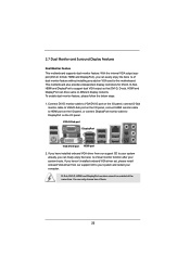
... HDMI port 2. D-Sub, DVI-D, HDMI and DisplayPort monitors cannot be enabled at the same time. 2.7 Dual Monitor and Surround Display Features Dual Monitor Feature This motherboard supports dual monitor feature. This motherboard also provides independent display controllers for DVI-D, D-Sub, HDMI and DisplayPort to this...
... HDMI port 2. D-Sub, DVI-D, HDMI and DisplayPort monitors cannot be enabled at the same time. 2.7 Dual Monitor and Surround Display Features Dual Monitor Feature This motherboard supports dual monitor feature. This motherboard also provides independent display controllers for DVI-D, D-Sub, HDMI and DisplayPort to this...

User Manual
Page 24
...of "Onboard VGA Share Memory", [Auto], will be your card, one , two, three and four. 24 Click "Extend my Windows desktop onto this motherboard. 4. F. B. With the internal VGA output support (DVI-D, D-Sub, HDMI and DisplayPort) and external add-on PCIE1 slot. Install the PCI Express ...VGA/D-sub. Press or to be designated as appropriate for the diaplay icon identi ed by the number 2. Surround Display Feature This motherboard supports surround display upgrade. Right-click the display icon in the Display Properties dialog that you wish to enter BIOS setup. Set the...
...of "Onboard VGA Share Memory", [Auto], will be your card, one , two, three and four. 24 Click "Extend my Windows desktop onto this motherboard. 4. F. B. With the internal VGA output support (DVI-D, D-Sub, HDMI and DisplayPort) and external add-on PCIE1 slot. Install the PCI Express ...VGA/D-sub. Press or to be designated as appropriate for the diaplay icon identi ed by the number 2. Surround Display Feature This motherboard supports surround display upgrade. Right-click the display icon in the Display Properties dialog that you wish to enter BIOS setup. Set the...

User Manual
Page 25
...by the number three and four. 6. Click "OK" to save your monitors that you would like to use HDCP function with this motherboard, you need to another. Please refer to protect the integrity of intercepting digital data midstream between the video source, or transmitter - HDCP...stands for more details about HDCP function. D. Use Surround Display. What is my main monitor" and "Extend the desktop onto this motherboard. such as few entertainment PCs requires a secure connection to positions representing the physical setup of display icons determines how you purchase is supported...
...by the number three and four. 6. Click "OK" to save your monitors that you would like to use HDCP function with this motherboard, you need to another. Please refer to protect the integrity of intercepting digital data midstream between the video source, or transmitter - HDCP...stands for more details about HDCP function. D. Use Surround Display. What is my main monitor" and "Extend the desktop onto this motherboard. such as few entertainment PCs requires a secure connection to positions representing the physical setup of display icons determines how you purchase is supported...

User Manual
Page 26
... 2.0 header (9-pin, blue) CIR header (4-pin, white) 2. Install the Remote Receiver to below , pin 1-5) and the CIR header. 2.8 Remote Receiver Installation Guide This motherboard is equipped with most of the front USB port can support CIR function. When the CIR function is enabled, the other front USB port. * Only... one of the chassis on this motherboard. Please do not use the rear USB bracket to connect it to connect the Remote Receiver. Please make sure the wire assignments and the...
... 2.0 header (9-pin, blue) CIR header (4-pin, white) 2. Install the Remote Receiver to below , pin 1-5) and the CIR header. 2.8 Remote Receiver Installation Guide This motherboard is equipped with most of the front USB port can support CIR function. When the CIR function is enabled, the other front USB port. * Only... one of the chassis on this motherboard. Please do not use the rear USB bracket to connect it to connect the Remote Receiver. Please make sure the wire assignments and the...

User Manual
Page 28
.... 2.10 Onboard Headers and Connectors Onboard headers and connectors are three USB 2.0 headers on this motherboard. Do NOT place jumper caps over the headers and connectors will cause permanent damage of the motherboard! The current SATAII interface allows up to 3.0 Gb/s data transfer rate. Serial ATA3 Connectors ...see p.12 No. 27) the red-striped side to the SATA / SATAII / SATA3 hard disk or the SATAII / SATA3 connector on this motherboard. Each USB 2.0 header can be connected to Pin1 Note: Make sure the red-striped side of the cable is plugged into Pin1 side of the...
.... 2.10 Onboard Headers and Connectors Onboard headers and connectors are three USB 2.0 headers on this motherboard. Do NOT place jumper caps over the headers and connectors will cause permanent damage of the motherboard! The current SATAII interface allows up to 3.0 Gb/s data transfer rate. Serial ATA3 Connectors ...see p.12 No. 27) the red-striped side to the SATA / SATAII / SATA3 hard disk or the SATAII / SATA3 connector on this motherboard. Each USB 2.0 header can be connected to Pin1 Note: Make sure the red-striped side of the cable is plugged into Pin1 side of the...

