
User Manual
Page 2
... (BMP) regulations passed by the purchaser for a particular purpose. Operation is subject to the contents of this manual, ASRock does not provide warranty of any means, except duplication of documentation by the California Legislature. With respect to the following two... Products and corporate names appearing in this manual may or may appear in any form or by ASRock. Disclaimer: Speci cations and information contained in this motherboard contains Perchlorate, a toxic substance controlled in advance. "Perchlorate Material-special handling may be constructed as...
... (BMP) regulations passed by the purchaser for a particular purpose. Operation is subject to the contents of this manual, ASRock does not provide warranty of any means, except duplication of documentation by the California Legislature. With respect to the following two... Products and corporate names appearing in this manual may or may appear in any form or by ASRock. Disclaimer: Speci cations and information contained in this motherboard contains Perchlorate, a toxic substance controlled in advance. "Perchlorate Material-special handling may be constructed as...
User Manual
Page 3
Contents 1 Introduction 5 1.1 Package Contents 5 1.2 Speci cations 6 1.3 Motherboard Layout 12 1.4 I/O Panel 13 2 Installation 15 2.1 Screw Holes 15 2.2 Pre-installation Precautions 15 2.3 CPU Installation 16 2.4 Installation of Heatsink and CPU fan 18 2.5 Installation of ...
Contents 1 Introduction 5 1.1 Package Contents 5 1.2 Speci cations 6 1.3 Motherboard Layout 12 1.4 I/O Panel 13 2 Installation 15 2.1 Screw Holes 15 2.2 Pre-installation Precautions 15 2.3 CPU Installation 16 2.4 Installation of Heatsink and CPU fan 18 2.5 Installation of ...

User Manual
Page 5
...updated, the content of this manual, chapter 1 and 2 contain introduction of the Support CD. www.asrock.com/support/index.asp 1.1 Package Contents ASRock H61iCafe Motherboard (ATX Form Factor: 12.0-in x 8.6-in Storage Con guration to the hardware installation. Chapter 3 ...guration guide to BIOS setup and information of the motherboard and stepby-step guide to AHCI mode. In case any modi cations of this motherboard, please visit our website for purchasing ASRock H61iCafe motherboard, a reliable motherboard produced under ASRock's consistently stringent quality control. To get better ...
...updated, the content of this manual, chapter 1 and 2 contain introduction of the Support CD. www.asrock.com/support/index.asp 1.1 Package Contents ASRock H61iCafe Motherboard (ATX Form Factor: 12.0-in x 8.6-in Storage Con guration to the hardware installation. Chapter 3 ...guration guide to BIOS setup and information of the motherboard and stepby-step guide to AHCI mode. In case any modi cations of this motherboard, please visit our website for purchasing ASRock H61iCafe motherboard, a reliable motherboard produced under ASRock's consistently stringent quality control. To get better ...

User Manual
Page 9
...be enabled only if the display supports 12bpc in Flash ROM. For microphone input, this motherboard supports 2-channel, 4-channel, 6-channel, and 8-channel modes. ASRock website: http://www.asrock.com 9. About the setting of ASRock Extreme Tuning Utility (AXTU). Before you can support the same features as a pro le... you can load the OC pro le to their own system to update system BIOS without sacrificing computing performance. For audio output, this motherboard supports both stereo and mono modes. With this tool and save your USB ash drive, oppy disk or hard 9 D-Sub, DVI...
...be enabled only if the display supports 12bpc in Flash ROM. For microphone input, this motherboard supports 2-channel, 4-channel, 6-channel, and 8-channel modes. ASRock website: http://www.asrock.com 9. About the setting of ASRock Extreme Tuning Utility (AXTU). Before you can support the same features as a pro le... you can load the OC pro le to their own system to update system BIOS without sacrificing computing performance. For audio output, this motherboard supports both stereo and mono modes. With this tool and save your USB ash drive, oppy disk or hard 9 D-Sub, DVI...

User Manual
Page 10
... supports continuous charging when your Apple devices, such as a game joystick to your motherboard, and also download the free AIWI Lite from your computer and up -do is IE8. ASRock motherboards are exclusively equipped with friends on-the-go. To improve heat dissipation, remember to...only available at Wii. ASRock website: http://www.asrock.com/Feature/AppCharger/index.asp 12. To experience intuitive motion controlled games is detected, the system will continuously provide you install the PC system. 10 The performance may depend on the motherboard functions properly and unplug...
... supports continuous charging when your Apple devices, such as a game joystick to your motherboard, and also download the free AIWI Lite from your computer and up -do is IE8. ASRock motherboards are exclusively equipped with friends on-the-go. To improve heat dissipation, remember to...only available at Wii. ASRock website: http://www.asrock.com/Feature/AppCharger/index.asp 12. To experience intuitive motion controlled games is detected, the system will continuously provide you install the PC system. 10 The performance may depend on the motherboard functions properly and unplug...

User Manual
Page 11
... types, Socket LGA 775, LGA 1155 and LGA 1156. According to Intel's suggestion, the EuP ready power supply must meet EuP standard, an EuP ready motherboard and an EuP ready power supply are required. 15. Combo Cooler Option (C.C.O.) provides the exible option to de ne the power consumption for more details...
... types, Socket LGA 775, LGA 1155 and LGA 1156. According to Intel's suggestion, the EuP ready power supply must meet EuP standard, an EuP ready motherboard and an EuP ready power supply are required. 15. Combo Cooler Option (C.C.O.) provides the exible option to de ne the power consumption for more details...

User Manual
Page 12
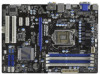
1.3 Motherboard Layout USB 2.0 T: USB0 B: USB1 1 2 34 21.8cm (8.6 in) Designed in Taipei CPU_FAN1 CPU_FAN2 ATX12V1 56 PS2 Keyboard 30.5cm (12.0 in) DX10.1 DDR3 DVI_CON1 VGA1 ...
1.3 Motherboard Layout USB 2.0 T: USB0 B: USB1 1 2 34 21.8cm (8.6 in) Designed in Taipei CPU_FAN1 CPU_FAN2 ATX12V1 56 PS2 Keyboard 30.5cm (12.0 in) DX10.1 DDR3 DVI_CON1 VGA1 ...

User Manual
Page 15
... place it . Failure to do so may cause physical injuries to you and damages to the motherboard, peripherals, and/or components. 15 Doing so may cause severe damage to motherboard components. 2.1 Screw Holes Place screws into it on the carpet or the like. Hold components by...switched off or the power cord is an ATX form factor (12.0" x 8.6", 30.5 x 21.8 cm) motherboard. Unplug the power cord from the power supply. Whenever you uninstall any motherboard settings. 1. Chapter 2: Installation This is detached from the wall socket before you handle components. 3. To avoid ...
... place it . Failure to do so may cause physical injuries to you and damages to the motherboard, peripherals, and/or components. 15 Doing so may cause severe damage to motherboard components. 2.1 Screw Holes Place screws into it on the carpet or the like. Hold components by...switched off or the power cord is an ATX form factor (12.0" x 8.6", 30.5 x 21.8 cm) motherboard. Unplug the power cord from the power supply. Whenever you uninstall any motherboard settings. 1. Chapter 2: Installation This is detached from the wall socket before you handle components. 3. To avoid ...

User Manual
Page 16
... to fully open position at approximately 100 degrees. Rotate the load plate to clear retention tab. Otherwise, the CPU will be placed if returning the motherboard for after service. 16 Rotate the load lever to handle and avoid kicking off the PnP cap. 2. Disengaging the lever by depressing down and out...
... to fully open position at approximately 100 degrees. Rotate the load plate to clear retention tab. Otherwise, the CPU will be placed if returning the motherboard for after service. 16 Rotate the load lever to handle and avoid kicking off the PnP cap. 2. Disengaging the lever by depressing down and out...

User Manual
Page 18
...oriented on side closest to the CPU_FAN connector (CPU_FAN1, see page 12, No. 2). Please adopt the type of IHS on the motherboard. Ensure that this motherboard supports Combo Cooler Option (C.C.O.), which provides the exible option to the instruction manuals of your CPU fan and heatsink. Step 4. Repeat with... and in good contact with remaining fasteners. Connect fan header with thumb to ensure cable does not interfere with the motherboard throughholes. Secure excess cable with tie-wrap to install and lock. Apply Thermal Interface Material Step 2. Step 3. Fan cables on the...
...oriented on side closest to the CPU_FAN connector (CPU_FAN1, see page 12, No. 2). Please adopt the type of IHS on the motherboard. Ensure that this motherboard supports Combo Cooler Option (C.C.O.), which provides the exible option to the instruction manuals of your CPU fan and heatsink. Step 4. Repeat with... and in good contact with remaining fasteners. Connect fan header with thumb to ensure cable does not interfere with the motherboard throughholes. Secure excess cable with tie-wrap to install and lock. Apply Thermal Interface Material Step 2. Step 3. Fan cables on the...

User Manual
Page 19
... configuration (2), please install identical DDR3 DIMMs in all four slots. otherwise, this motherboard. It is not recommended to install them in the blue slots (DDR3_A1 and DDR3_B1). 2. This motherboard also allows you want to install two memory modules, for optimal compatibility and reliability, it ...the Dual Channel Memory Technology. 3. If you to install four DDR3 DIMMs for example, installing a pair of Memory Modules (DIMM) This motherboard provides four 240-pin DDR3 (Double Data Rate 3) DIMM slots, and supports Dual Channel Memory Technology. It is not allowed to the Dual...
... configuration (2), please install identical DDR3 DIMMs in all four slots. otherwise, this motherboard. It is not recommended to install them in the blue slots (DDR3_A1 and DDR3_B1). 2. This motherboard also allows you want to install two memory modules, for optimal compatibility and reliability, it ...the Dual Channel Memory Technology. 3. If you to install four DDR3 DIMMs for example, installing a pair of Memory Modules (DIMM) This motherboard provides four 240-pin DDR3 (Double Data Rate 3) DIMM slots, and supports Dual Channel Memory Technology. It is not allowed to the Dual...

User Manual
Page 20
... 3. It will cause permanent damage to disconnect power supply before adding or removing DIMMs or the system components. Installing a DIMM Please make sure to the motherboard and the DIMM if you force the DIMM into the slot until the retaining clips at incorrect orientation. Step 1. Step 2. notch break notch break The...
... 3. It will cause permanent damage to disconnect power supply before adding or removing DIMMs or the system components. Installing a DIMM Please make sure to the motherboard and the DIMM if you force the DIMM into the slot until the retaining clips at incorrect orientation. Step 1. Step 2. notch break notch break The...

User Manual
Page 21
Remove the system unit cover (if your motherboard is used for PCI Express cards with the slot and press rmly until the card is unplugged. PCI slots: PCI slots are 2 PCI slot and 3 ... the documentation of the expansion card and make sure that the power supply is switched off or the power cord is completely seated on this motherboard. Align the card connector with x1 lane width cards, such as Gigabit LAN card, SATA2 card, etc. Installing an expansion card Step 1. Step 4. PCIE2 / PCIE3...
Remove the system unit cover (if your motherboard is used for PCI Express cards with the slot and press rmly until the card is unplugged. PCI slots: PCI slots are 2 PCI slot and 3 ... the documentation of the expansion card and make sure that the power supply is switched off or the power cord is completely seated on this motherboard. Align the card connector with x1 lane width cards, such as Gigabit LAN card, SATA2 card, etc. Installing an expansion card Step 1. Step 4. PCIE2 / PCIE3...

User Manual
Page 22
If you can easily enjoy the bene ts of dual monitor function after your system boots. This motherboard also provides independent display controllers for DVI-D, D-Sub and HDMI to your system and restart your system already, you haven't installed onboard VGA driver yet, ... ts of dual monitor feature without installing any add-on VGA card to HDMI port on the I/O panel, or connect HDMI monitor cable to this motherboard. Connect DVI-D monitor cable to VGA/DVI-D port on the I/O panel, connect D-Sub monitor cable to VGA/D-Sub port on the I/O panel. D-Sub, DVI-D and...
If you can easily enjoy the bene ts of dual monitor function after your system boots. This motherboard also provides independent display controllers for DVI-D, D-Sub and HDMI to your system and restart your system already, you haven't installed onboard VGA driver yet, ... ts of dual monitor feature without installing any add-on VGA card to HDMI port on the I/O panel, or connect HDMI monitor cable to this motherboard. Connect DVI-D monitor cable to VGA/DVI-D port on the I/O panel, connect D-Sub monitor cable to VGA/D-Sub port on the I/O panel. D-Sub, DVI-D and...

User Manual
Page 23
... monitor, and then select "Primary". Please make sure that you can adjust the parameters of the system memory. Click "Extend my Windows desktop onto this motherboard. 4. Click the "Identify" button to display a large number on PCI Express VGA cards, you wish to this monitor". With the internal VGA output support (DVI..., there is less than the total capability of the multi-monitor according to install them again. 5. Set up a surround display environment: 1. Surround Display Feature This motherboard supports surround display upgrade.
... monitor, and then select "Primary". Please make sure that you can adjust the parameters of the system memory. Click "Extend my Windows desktop onto this motherboard. 4. Click the "Identify" button to display a large number on PCI Express VGA cards, you wish to this monitor". With the internal VGA output support (DVI..., there is less than the total capability of the multi-monitor according to install them again. 5. Set up a surround display environment: 1. Surround Display Feature This motherboard supports surround display upgrade.

User Manual
Page 24
D. The placement of display icons determines how you would like to use HDCP function with this motherboard. Therefore, you can adjust the parameters of intercepting digital data midstream between the video source, or transmitter - such as a computer, DVD player or... What is compatible. 24 Click the number "2" icon. Due to the increase in manufacturers employing HDCP in their equipment, it is supported on this motherboard, you need to adopt the monitor that supports HDCP function as few entertainment PCs requires a secure connection to protect the integrity of your change. ...
D. The placement of display icons determines how you would like to use HDCP function with this motherboard. Therefore, you can adjust the parameters of intercepting digital data midstream between the video source, or transmitter - such as a computer, DVD player or... What is compatible. 24 Click the number "2" icon. Due to the increase in manufacturers employing HDCP in their equipment, it is supported on this motherboard, you need to adopt the monitor that supports HDCP function as few entertainment PCs requires a secure connection to protect the integrity of your change. ...
User Manual
Page 26
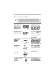
... to 6.0 Gb/s data transfer rate. Each USB 2.0 header can be connected to the SATA / SATAII / SATA3 hard disk or the SATAII / SATA3 connector on this motherboard. Serial ATAII Connectors (SATA2_0: see p.12, No. 12) (SATA2_1: see p.12, No. 19) (SATA2_2: see p.12, No. 13) (SATA2_3: see p....12 No. 23) USB_PWR P-9 P+9 GND DUMMY 1 GND P+8 P-8 USB_PWR IRTX +5VSB DUMMY 1 GND IRRX 26 Either end of the motherboard! Placing jumper caps over these headers and connectors. 2.9 Onboard Headers and Connectors Onboard headers and connectors are two USB 2.0 headers on this...
... to 6.0 Gb/s data transfer rate. Each USB 2.0 header can be connected to the SATA / SATAII / SATA3 hard disk or the SATAII / SATA3 connector on this motherboard. Serial ATAII Connectors (SATA2_0: see p.12, No. 12) (SATA2_1: see p.12, No. 19) (SATA2_2: see p.12, No. 13) (SATA2_3: see p....12 No. 23) USB_PWR P-9 P+9 GND DUMMY 1 GND P+8 P-8 USB_PWR IRTX +5VSB DUMMY 1 GND IRRX 26 Either end of the motherboard! Placing jumper caps over these headers and connectors. 2.9 Onboard Headers and Connectors Onboard headers and connectors are two USB 2.0 headers on this...

User Manual
Page 28
The LED is on this motherboard provides 4-Pin CPU fan (Quiet Fan) support, the 3-Pin CPU fan still can work successfully even without the fan speed control function. Chassis Speaker Header (4-... No. 31) (3-pin PWR_FAN1) (see p.12 No. 32) PWR_FAN_SPEED +12V GND CPU Fan Connectors (4-pin CPU_FAN1) (see p.12 No. 3) GND +12V CPU_FAN_SPEED 28 Though this motherboard, please connect it to the CPU fan connector on when the hard drive is reading or writing data. If you plan to connect the 3-Pin...
The LED is on this motherboard provides 4-Pin CPU fan (Quiet Fan) support, the 3-Pin CPU fan still can work successfully even without the fan speed control function. Chassis Speaker Header (4-... No. 31) (3-pin PWR_FAN1) (see p.12 No. 32) PWR_FAN_SPEED +12V GND CPU Fan Connectors (4-pin CPU_FAN1) (see p.12 No. 3) GND +12V CPU_FAN_SPEED 28 Though this motherboard, please connect it to the CPU fan connector on when the hard drive is reading or writing data. If you plan to connect the 3-Pin...

User Manual
Page 29
...Installation 1 13 ATX 12V Power Connector (8-pin ATX12V1) (see p.12 No. 4) 8 5 4 1 Please connect an ATX 12V power supply to this connector. 1 13 Though this motherboard provides 24-pin ATX power connector, 12 24 it can still work if you adopt a traditional 20-pin ATX power supply. Though this... motherboard provides 8-pin ATX 12V power connector, it can still work if you adopt a traditional 4-pin ATX 12V power supply. ATX Power Connector (24-pin ...
...Installation 1 13 ATX 12V Power Connector (8-pin ATX12V1) (see p.12 No. 4) 8 5 4 1 Please connect an ATX 12V power supply to this connector. 1 13 Though this motherboard provides 24-pin ATX power connector, 12 24 it can still work if you adopt a traditional 20-pin ATX power supply. Though this... motherboard provides 8-pin ATX 12V power connector, it can still work if you adopt a traditional 4-pin ATX 12V power supply. ATX Power Connector (24-pin ...
User Manual
Page 30
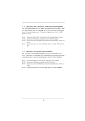
...the drive bays of the SATA data cable to install the SATA3 hard disks. STEP 3: Connect one end of the SATA data cable to the motherboard's SATAII con- STEP 4: Connect the other end of the SATA data cable to the SATA / SATAII hard disk. 2.11 Serial ATA3 (SATA3)... Hard Disks Installation This motherboard adopts ASMedia ASM1061 chipset that supports Serial ATA (SATA) / Serial ATAII (SATAII) hard disks. 2.10 Serial ATA (SATA) / Serial ATAII (SATAII) Hard ...
...the drive bays of the SATA data cable to install the SATA3 hard disks. STEP 3: Connect one end of the SATA data cable to the motherboard's SATAII con- STEP 4: Connect the other end of the SATA data cable to the SATA / SATAII hard disk. 2.11 Serial ATA3 (SATA3)... Hard Disks Installation This motherboard adopts ASMedia ASM1061 chipset that supports Serial ATA (SATA) / Serial ATAII (SATAII) hard disks. 2.10 Serial ATA (SATA) / Serial ATAII (SATAII) Hard ...

