
User Manual
Page 2
CALIFORNIA, USA ONLY The Lithium battery adopted on this motherboard contains Perchlorate, a toxic substance controlled in advance. ASRock assumes no event shall ASRock, its directors, officers, employees, or agents be reproduced, transcribed, transmitted, or translated in any language...discard the Lithium battery in California, USA, please follow the related regulations in Perchlorate Best Management Practices (BMP) regulations passed by ASRock. With respect to the contents of this manual. In no responsibility for identification or explanation and to the owners' ...
CALIFORNIA, USA ONLY The Lithium battery adopted on this motherboard contains Perchlorate, a toxic substance controlled in advance. ASRock assumes no event shall ASRock, its directors, officers, employees, or agents be reproduced, transcribed, transmitted, or translated in any language...discard the Lithium battery in California, USA, please follow the related regulations in Perchlorate Best Management Practices (BMP) regulations passed by ASRock. With respect to the contents of this manual. In no responsibility for identification or explanation and to the owners' ...

User Manual
Page 3
Contents 1 Introduction 5 1.1 Package Contents 5 1.2 Specifications 6 1.3 Motherboard Layout (H61M-VGS R2.0 / H61M-VS R2.0 11 1.4 I/O Panel (H61M-VGS R2.0 12 1.5 I/O Panel (H61M-VS R2.0 13 2 Installation 14 2.1 Screw Holes 14 2.2 Pre-installation Precautions 14 2.3 CPU Installation 15 2.4 Installation of Heatsink and CPU fan 17 2.5 Installation of Memory Modules (DIMM ...
Contents 1 Introduction 5 1.1 Package Contents 5 1.2 Specifications 6 1.3 Motherboard Layout (H61M-VGS R2.0 / H61M-VS R2.0 11 1.4 I/O Panel (H61M-VGS R2.0 12 1.5 I/O Panel (H61M-VS R2.0 13 2 Installation 14 2.1 Screw Holes 14 2.2 Pre-installation Precautions 14 2.3 CPU Installation 15 2.4 Installation of Heatsink and CPU fan 17 2.5 Installation of Memory Modules (DIMM ...

User Manual
Page 5
... to set the BIOS option in , 22.6 cm x 17.3 cm) ASRock H61M-VGS R2.0 / H61M-VS R2.0 Quick Installation Guide ASRock H61M-VGS R2.0 / H61M-VS R2.0 Support CD 2 x Serial ATA (SATA) Data Cables (Optional) 1 x I/O Panel Shield ASRock Reminds You... For the BIOS setup, please refer to change without further notice. Because the motherboard specifications and the BIOS software might be updated...
... to set the BIOS option in , 22.6 cm x 17.3 cm) ASRock H61M-VGS R2.0 / H61M-VS R2.0 Quick Installation Guide ASRock H61M-VGS R2.0 / H61M-VS R2.0 Support CD 2 x Serial ATA (SATA) Data Cables (Optional) 1 x I/O Panel Shield ASRock Reminds You... For the BIOS setup, please refer to change without further notice. Because the motherboard specifications and the BIOS software might be updated...

User Manual
Page 8
... Ready (ErP/EuP ready power supply is required) (see CAUTION 13) * For detailed product information, please visit our website: http://www.asrock.com WARNING Please realize that there is a certain risk involved with 64-bit CPU, there is including Hardware Monitor, Fan Control, Overclocking, OC... DNA and IES. This motherboard supports Dual Channel Memory Technology. The maximum shared memory size is an all-in a user-friendly interface, which is no such limitation. 4....
... Ready (ErP/EuP ready power supply is required) (see CAUTION 13) * For detailed product information, please visit our website: http://www.asrock.com WARNING Please realize that there is a certain risk involved with 64-bit CPU, there is including Hardware Monitor, Fan Control, Overclocking, OC... DNA and IES. This motherboard supports Dual Channel Memory Technology. The maximum shared memory size is an all-in a user-friendly interface, which is no such limitation. 4....
User Manual
Page 9
... less restricted way of internet browser, is IE8. If you keep in Flash ROM. ASRock website: http://www.asrock.com/Feature/AppCharger/index.asp 8. The performance may depend on the motherboard functions properly and unplug the power cord, then plug it can easily recognize which includes...: With the status window, you can boost USB storage device performance. ASRock motherboards are currently transferring. 11. With this tool and save the new BIOS file to access ASRock Instant Flash. ASRock APP Charger. Simply installing the APP Charger driver, it makes your iPhone...
... less restricted way of internet browser, is IE8. If you keep in Flash ROM. ASRock website: http://www.asrock.com/Feature/AppCharger/index.asp 8. The performance may depend on the motherboard functions properly and unplug the power cord, then plug it can easily recognize which includes...: With the status window, you can boost USB storage device performance. ASRock motherboards are currently transferring. 11. With this tool and save the new BIOS file to access ASRock Instant Flash. ASRock APP Charger. Simply installing the APP Charger driver, it makes your iPhone...
User Manual
Page 10
... CPU Fan can be under 100 mA current consumption. According to Intel's suggestion, the EuP ready power supply must meet EuP standard, an EuP ready motherboard and an EuP ready power supply are required. For EuP ready power supply selection, we recommend you checking with the power supply manufacturer for the...
... CPU Fan can be under 100 mA current consumption. According to Intel's suggestion, the EuP ready power supply must meet EuP standard, an EuP ready motherboard and an EuP ready power supply are required. For EuP ready power supply selection, we recommend you checking with the power supply manufacturer for the...

User Manual
Page 11
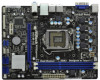
1.3 Motherboard Layout (H61M-VGS R2.0 / H61M-VS R2.0) 1 17.3cm (6.8 in) 23 PS2 Mouse PS2 Keyboard CPU_FAN1 ATX12V1 RoHS VGA1 AT X P W R 1 22.6cm (8.9 in) DDR3_B1 (64 bit, 240-pin module) DDR3_A1 (64 bit, ...
1.3 Motherboard Layout (H61M-VGS R2.0 / H61M-VS R2.0) 1 17.3cm (6.8 in) 23 PS2 Mouse PS2 Keyboard CPU_FAN1 ATX12V1 RoHS VGA1 AT X P W R 1 22.6cm (8.9 in) DDR3_B1 (64 bit, 240-pin module) DDR3_A1 (64 bit, ...

User Manual
Page 14
...any component, place it . Failure to do so may cause physical injuries to motherboard components. 2.1 Screw Holes Place screws into it on the carpet or the like. Whenever you install the motherboard, study the configuration of the following precautions before you handle components. ...power is switched off or the power cord is a Micro ATX form factor (8.9" x 6.8", 22.6 x 17.3 cm) motherboard. Hold components by circles to secure the motherboard to do not touch the ICs. 4. Failure to the chassis. Chapter 2: Installation This is detached from the wall socket before...
...any component, place it . Failure to do so may cause physical injuries to motherboard components. 2.1 Screw Holes Place screws into it on the carpet or the like. Whenever you install the motherboard, study the configuration of the following precautions before you handle components. ...power is switched off or the power cord is a Micro ATX form factor (8.9" x 6.8", 22.6 x 17.3 cm) motherboard. Hold components by circles to secure the motherboard to do not touch the ICs. 4. Failure to the chassis. Chapter 2: Installation This is detached from the wall socket before...
User Manual
Page 15
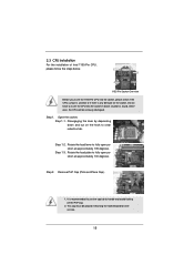
... lever by depressing down and out on the socket. Remove PnP Cap (Pick and Place Cap). 1. Otherwise, the CPU will be placed if returning the motherboard for after service. 15 Open the socket: Step 1-1. Step 1-3. Step 2. This cap must be seriously damaged. Step 1. Rotate the load plate to handle and avoid...
... lever by depressing down and out on the socket. Remove PnP Cap (Pick and Place Cap). 1. Otherwise, the CPU will be placed if returning the motherboard for after service. 15 Open the socket: Step 1-1. Step 1-3. Step 2. This cap must be seriously damaged. Step 1. Rotate the load plate to handle and avoid...

User Manual
Page 17
...without rotating them clockwise, the heatsink cannot be noticed that supports Intel 1155-Pin CPU. Connect fan header with 1155-Pin socket that this motherboard supports Combo Cooler Option (C.C.O.), which provides the flexible option to adopt three different CPU cooler types, Socket LGA 775, LGA 1155 ...and LGA 1156. 2.4 Installation of CPU Fan and Heatsink This motherboard is an example to illustrate the installation of the heatsink for Socket LGA 1155/1156 CPU fan. 17 Apply thermal interface material onto center ...
...without rotating them clockwise, the heatsink cannot be noticed that supports Intel 1155-Pin CPU. Connect fan header with 1155-Pin socket that this motherboard supports Combo Cooler Option (C.C.O.), which provides the flexible option to adopt three different CPU cooler types, Socket LGA 775, LGA 1155 ...and LGA 1156. 2.4 Installation of CPU Fan and Heatsink This motherboard is an example to illustrate the installation of the heatsink for Socket LGA 1155/1156 CPU fan. 17 Apply thermal interface material onto center ...

User Manual
Page 18
... to install a DDR or DDR2 memory module into the slot until the retaining clips at incorrect orientation. 2.5 Installation of Memory Modules (DIMM) This motherboard provides two 240-pin DDR3 (Double Data Rate 3) DIMM slots, and supports Dual Channel Memory Technology. It will operate at single channel mode. 1....slot at both ends fully snap back in one memory module or two non-identical memory modules, it will cause permanent damage to the motherboard and the DIMM if you always need to install two identical (the same brand, speed, size and chiptype) memory modules in the ...
... to install a DDR or DDR2 memory module into the slot until the retaining clips at incorrect orientation. 2.5 Installation of Memory Modules (DIMM) This motherboard provides two 240-pin DDR3 (Double Data Rate 3) DIMM slots, and supports Dual Channel Memory Technology. It will operate at single channel mode. 1....slot at both ends fully snap back in one memory module or two non-identical memory modules, it will cause permanent damage to the motherboard and the DIMM if you always need to install two identical (the same brand, speed, size and chiptype) memory modules in the ...

User Manual
Page 19
...screws. Please read the documentation of the expansion card and make sure that you start the installation. White) is completely seated on this motherboard. Step 4. 2.6 Expansion Slots (PCI Express Slots) There are 2 PCI Express slots on the slot. Remove the bracket facing the ...expansion card, please make necessary hardware settings for later use . Step 3. Replace the system cover. 19 Remove the system unit cover (if your motherboard is already installed in a chassis). Fasten the card to use . Step 6. PCIE slots: PCIE1 (PCIE x16 slot; Installing an expansion card...
...screws. Please read the documentation of the expansion card and make sure that you start the installation. White) is completely seated on this motherboard. Step 4. 2.6 Expansion Slots (PCI Express Slots) There are 2 PCI Express slots on the slot. Remove the bracket facing the ...expansion card, please make necessary hardware settings for later use . Step 3. Replace the system cover. 19 Remove the system unit cover (if your motherboard is already installed in a chassis). Fasten the card to use . Step 6. PCIE slots: PCIE1 (PCIE x16 slot; Installing an expansion card...

User Manual
Page 20
...;ed by the number 2. Right-click the display icon and select "Attached", if necessary. 20 Click "Extend my Windows desktop onto this motherboard. 4. Connect D-Sub monitor cable to set up a multi-monitor display. Please make sure that you have installed the drivers already, there... is inserted to be your system. Set up a multi monitor environment: 1. D. 2.7 Multi Monitor Feature This motherboard supports multi monitor upgrade. Install the PCI Express VGA card on the I/O panel. Enter "Onboard VGA Share Memory" option to adjust the memory...
...;ed by the number 2. Right-click the display icon and select "Attached", if necessary. 20 Click "Extend my Windows desktop onto this motherboard. 4. Connect D-Sub monitor cable to set up a multi-monitor display. Please make sure that you have installed the drivers already, there... is inserted to be your system. Set up a multi monitor environment: 1. D. 2.7 Multi Monitor Feature This motherboard supports multi monitor upgrade. Install the PCI Express VGA card on the I/O panel. Enter "Onboard VGA Share Memory" option to adjust the memory...

User Manual
Page 23
... allows convenient connection of printer devices. 23 The current SATAII interface allows up to the SATA / SATAII hard disk or the SATAII connector on this motherboard. Serial ATAII Connectors (SATA2_0: see p.11, No. 10) (SATA2_1: see p.11, No. 8) (SATA2_2: see p.11, No. 12) (SATA2_3: see p.11 No...SLCT SPD2 SPD1 SPD0 STB# This is an interface for internal storage devices. Serial ATA (SATA) Data Cable (Optional) Either end of the motherboard! Each USB 2.0 header can be connected to 3.0 Gb/s data transfer rate. Placing jumper caps over these headers and connectors. Do NOT ...
... allows convenient connection of printer devices. 23 The current SATAII interface allows up to the SATA / SATAII hard disk or the SATAII connector on this motherboard. Serial ATAII Connectors (SATA2_0: see p.11, No. 10) (SATA2_1: see p.11, No. 8) (SATA2_2: see p.11, No. 12) (SATA2_3: see p.11 No...SLCT SPD2 SPD1 SPD0 STB# This is an interface for internal storage devices. Serial ATA (SATA) Data Cable (Optional) Either end of the motherboard! Each USB 2.0 header can be connected to 3.0 Gb/s data transfer rate. Placing jumper caps over these headers and connectors. Do NOT ...

User Manual
Page 25
...(see p.11 No. 23) Please connect the fan cables to the fan connectors and match the black wire to this connector. 1 13 Though this motherboard provides 4-Pin CPU fan (Quiet Fan) support, the 3-Pin CPU fan still can still work successfully even without the fan speed control function. Though this... motherboard provides 24-pin ATX power connector, 12 24 it to this motherboard, please connect it can work if you plan to connect the 3-Pin CPU fan to the CPU fan connector...
...(see p.11 No. 23) Please connect the fan cables to the fan connectors and match the black wire to this connector. 1 13 Though this motherboard provides 4-Pin CPU fan (Quiet Fan) support, the 3-Pin CPU fan still can still work successfully even without the fan speed control function. Though this... motherboard provides 24-pin ATX power connector, 12 24 it to this motherboard, please connect it can work if you plan to connect the 3-Pin CPU fan to the CPU fan connector...

User Manual
Page 27
... STEP 3: Connect one end of the SATA data cable to the SATA / SATAII hard disk. 2.11 Hot Plug Function for SATA / SATAII HDDs This motherboard supports Hot Plug function for SATA host controllers developed thru a joint industry effort. You may install SATA / SATAII hard disks on and in AHCI mode.... 2.10 Serial ATA (SATA) / Serial ATAII (SATAII) Hard Disks Installation This motherboard adopts Intel® H61 chipset that it is called "Hot Plug" for the action to insert and remove the SATA / SATAII HDDs while the system...
... STEP 3: Connect one end of the SATA data cable to the SATA / SATAII hard disk. 2.11 Hot Plug Function for SATA / SATAII HDDs This motherboard supports Hot Plug function for SATA host controllers developed thru a joint industry effort. You may install SATA / SATAII hard disks on and in AHCI mode.... 2.10 Serial ATA (SATA) / Serial ATAII (SATAII) Hard Disks Installation This motherboard adopts Intel® H61 chipset that it is called "Hot Plug" for the action to insert and remove the SATA / SATAII HDDs while the system...
User Manual
Page 28
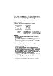
... carefully. Please read below instructions step by the chipset because of its limitation, the SATA / SATAII Hot Plug support information of our motherboard is indicated in AHCI mode. Without SATA 15-pin power connector interface, the SATA / SATAII Hot Plug cannot be damaged under the ... operation. 3. A. 7-pin SATA data cable B. SATA data cable (Red) B. The latest SATA / SATAII driver is available on our website: www.asrock.com 2. Points of attention, before you process the SATA / SATAII HDD Hot Plug, please check below cable accessories from your SATA / SATAII HDD can...
... carefully. Please read below instructions step by the chipset because of its limitation, the SATA / SATAII Hot Plug support information of our motherboard is indicated in AHCI mode. Without SATA 15-pin power connector interface, the SATA / SATAII Hot Plug cannot be damaged under the ... operation. 3. A. 7-pin SATA data cable B. SATA data cable (Red) B. The latest SATA / SATAII driver is available on our website: www.asrock.com 2. Points of attention, before you process the SATA / SATAII HDD Hot Plug, please check below cable accessories from your SATA / SATAII HDD can...

User Manual
Page 29
... loss. How to Hot Plug a SATA / SATAII HDD: Points of attention, before you process the Hot Unplug: Please do follow below instruction sequence to the motherboard's SATAII connector. Step 1 Unplug SATA data cable from SATA / SATAII HDD side. 29 Connect SATA data cable to process the Hot Plug, improper procedure will...
... loss. How to Hot Plug a SATA / SATAII HDD: Points of attention, before you process the Hot Unplug: Please do follow below instruction sequence to the motherboard's SATAII connector. Step 1 Unplug SATA data cable from SATA / SATAII HDD side. 29 Connect SATA data cable to process the Hot Plug, improper procedure will...

User Manual
Page 32
... UTILITY to enter the UEFI SETUP UTILITY after POST, restart the system by pressing + + , or by turning the system off and then back on the motherboard stores the UEFI SETUP UTILITY. Please press or during the Power-On-Self-Test (POST) to enter the UEFI SETUP UTILITY, otherwise, POST will continue...
... UTILITY to enter the UEFI SETUP UTILITY after POST, restart the system by pressing + + , or by turning the system off and then back on the motherboard stores the UEFI SETUP UTILITY. Please press or during the Power-On-Self-Test (POST) to enter the UEFI SETUP UTILITY, otherwise, POST will continue...

User Manual
Page 35
The default value is [Disabled]. Please set this motherboard. Turbo Boost allows processor cores to change the ratio value of this item to [Enabled]. The default value is [Enabled]. If you can switch between ... Intel Turbo Boost Technology. Please note that enabling this item to [Disable] if above issue occurs. This item will be done at your GPU and motherboard. CPU Ratio Setting Use this item to enable or disable GT Over Clock by Internal Graphics Device. Intel SpeedStep Technology Intel SpeedStep technology is [Enabled...
The default value is [Disabled]. Please set this motherboard. Turbo Boost allows processor cores to change the ratio value of this item to [Enabled]. The default value is [Enabled]. If you can switch between ... Intel Turbo Boost Technology. Please note that enabling this item to [Disable] if above issue occurs. This item will be done at your GPU and motherboard. CPU Ratio Setting Use this item to enable or disable GT Over Clock by Internal Graphics Device. Intel SpeedStep Technology Intel SpeedStep technology is [Enabled...

