User Manual
Page 6
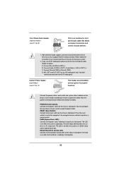
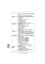
... LAN Cable Detection - PCIE x1 Gigabit LAN 10/100/1000 Mb/s - resolution up to -Use USB 2.0 Ports 6 1.2 Specifications Platform CPU Chipset Memory Expansion Slot Graphics Audio LAN Rear Panel I /O Panel - 1 x PS/2 Mouse Port - 1 x PS/2 Keyboard Port - 1 x Parallel Port (ECP/EPP Support) - 1 x Serial Port: COM1 - 1 x VGA Port - 4 x Ready-to 2048x1536 @ 75Hz - 5.1 CH HD...
... LAN Cable Detection - PCIE x1 Gigabit LAN 10/100/1000 Mb/s - resolution up to -Use USB 2.0 Ports 6 1.2 Specifications Platform CPU Chipset Memory Expansion Slot Graphics Audio LAN Rear Panel I /O Panel - 1 x PS/2 Mouse Port - 1 x PS/2 Keyboard Port - 1 x Parallel Port (ECP/EPP Support) - 1 x Serial Port: COM1 - 1 x VGA Port - 4 x Ready-to 2048x1536 @ 75Hz - 5.1 CH HD...
User Manual
Page 7
... Auto-Adjust by CPU Temperature) 7 CPU/Chassis/Power FAN connector - 24 pin ATX power connector - 8 pin 12V power connector - ASRock Extreme Tuning Utility (AXTU) (see CAUTION 9) - OEM and Trial; Boot Failure Guard (B.F.G.) - HD Audio Jack: Line in/Front Speaker/Microphone - 4 x SATA2 3.0 Gb/s connectors, support NCQ, AHCI and Hot Plug functions - 1 x IR header...
... Auto-Adjust by CPU Temperature) 7 CPU/Chassis/Power FAN connector - 24 pin ATX power connector - 8 pin 12V power connector - ASRock Extreme Tuning Utility (AXTU) (see CAUTION 9) - OEM and Trial; Boot Failure Guard (B.F.G.) - HD Audio Jack: Line in/Front Speaker/Microphone - 4 x SATA2 3.0 Gb/s connectors, support NCQ, AHCI and Hot Plug functions - 1 x IR header...

User Manual
Page 11
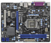
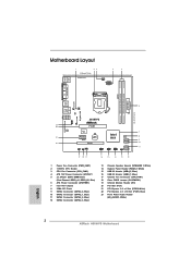
... USB 2.0 T: USB0 B: USB1 6 USB 2.0 T: USB2 Top: B: USB3 RJ-45 LAN PHY 1 HD_AUDIO1 Fast USB X Top: LINE IN Center: FRONT Bottom: MIC IN H61M-PS ErP/EuP Ready 23 22 AUDIO CODEC 21 20 PCIE1 Super I/O PCIE2 RoHS CMOS Battery PCI1 IR1 1 CHA_FAN1 CLRCMOS1 1 USB6_7 1 Intel H61 32Mb BIOS SATA2_0 USB4_5 1 PANEL1 PLED PWRBTN... Infrared Module Header (IR1) 20 PCI Slot (PCI1) 21 PCI Express 2.0 x1 Slot (PCIE2, White) 22 PCI Express 2.0 x16 Slot (PCIE1, Blue) 23 Front Panel Audio Header (HD_AUDIO1, White) 11
... USB 2.0 T: USB0 B: USB1 6 USB 2.0 T: USB2 Top: B: USB3 RJ-45 LAN PHY 1 HD_AUDIO1 Fast USB X Top: LINE IN Center: FRONT Bottom: MIC IN H61M-PS ErP/EuP Ready 23 22 AUDIO CODEC 21 20 PCIE1 Super I/O PCIE2 RoHS CMOS Battery PCI1 IR1 1 CHA_FAN1 CLRCMOS1 1 USB6_7 1 Intel H61 32Mb BIOS SATA2_0 USB4_5 1 PANEL1 PLED PWRBTN... Infrared Module Header (IR1) 20 PCI Slot (PCI1) 21 PCI Express 2.0 x1 Slot (PCIE2, White) 22 PCI Express 2.0 x16 Slot (PCIE1, Blue) 23 Front Panel Audio Header (HD_AUDIO1, White) 11
User Manual
Page 12
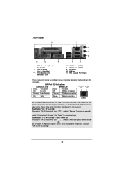
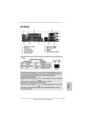
...your system. Then you will find "VIA HD Audio Deck" tool on the bottom. Click "Power" to save your change . 12 Please follow below for the LAN port LED indications. Please refer to the LAN port. 1.4 I/O Panel 1 2 3 4 5 6 11 10 9 1 PS/2 Mouse Port (Green) 2 Parallel Port * 3 LAN ...and click "OK" to save your change . For Windows® 7 / 7 64-bit / VistaTM / VistaTM 64-bit OS: Please click "VIA HD Audio Deck" icon , and click "Advanced Options" on the left side on your computer, you are two LED next to the table below instructions according to...
...your system. Then you will find "VIA HD Audio Deck" tool on the bottom. Click "Power" to save your change . 12 Please follow below for the LAN port LED indications. Please refer to the LAN port. 1.4 I/O Panel 1 2 3 4 5 6 11 10 9 1 PS/2 Mouse Port (Green) 2 Parallel Port * 3 LAN ...and click "OK" to save your change . For Windows® 7 / 7 64-bit / VistaTM / VistaTM 64-bit OS: Please click "VIA HD Audio Deck" icon , and click "Advanced Options" on the left side on your computer, you are two LED next to the table below instructions according to...
User Manual
Page 23
... drive is operating. The LED is on when the system is reading or writing data. 23 C. You don't need to connect them for HD audio panel only. PWRBTN (Power Switch): Connect to the hard drive activity LED on the chassis front panel. D. MIC_RET and OUT_RET are for AC'97... panel wire on the chassis front panel. Please follow the instruction in S3/S4 sleep state or powered off (S5). If you use AC'97 audio panel, please install it to function correctly. Connect Mic_IN (MIC) to perform a normal restart. B. Connect the power switch, reset switch and system status indicator...
... drive is operating. The LED is on when the system is reading or writing data. 23 C. You don't need to connect them for HD audio panel only. PWRBTN (Power Switch): Connect to the hard drive activity LED on the chassis front panel. D. MIC_RET and OUT_RET are for AC'97... panel wire on the chassis front panel. Please follow the instruction in S3/S4 sleep state or powered off (S5). If you use AC'97 audio panel, please install it to function correctly. Connect Mic_IN (MIC) to perform a normal restart. B. Connect the power switch, reset switch and system status indicator...

User Manual
Page 41
Onboard LAN This allows you to set this option to boot up when the power recovers. Onboard HD Audio Select [Auto], [Enabled] or [Disabled] for the onboard HD Audio Front Panel. ACPI HPET Table Use this option to turn off Power LED when the system is plugged. The keyboard LED will be turned... AC/power loss. If [Power On] is selected, the AC/power resumes and the system starts to [Enabled] if you select [Auto], the onboard HD Audio will also be disabled when PCI Sound Card is power on AC/Power Loss This allows you to enable or disable the "Onboard LAN" feature...
Onboard LAN This allows you to set this option to boot up when the power recovers. Onboard HD Audio Select [Auto], [Enabled] or [Disabled] for the onboard HD Audio Front Panel. ACPI HPET Table Use this option to turn off Power LED when the system is plugged. The keyboard LED will be turned... AC/power loss. If [Power On] is selected, the AC/power resumes and the system starts to [Enabled] if you select [Auto], the onboard HD Audio will also be disabled when PCI Sound Card is power on AC/Power Loss This allows you to enable or disable the "Onboard LAN" feature...
Quick Installation Guide
Page 2
... USB 2.0 T: USB0 B: USB1 6 USB 2.0 T: USB2 Top: B: USB3 RJ-45 LAN PHY 1 HD_AUDIO1 Fast USB X Top: LINE IN Center: FRONT Bottom: MIC IN H61M-PS ErP/EuP Ready 23 22 AUDIO CODEC 21 20 PCIE1 Super I/O PCIE2 RoHS CMOS Battery PCI1 IR1 1 CHA_FAN1 CLRCMOS1 1 USB6_7 1 Intel H61 32Mb BIOS SATA2_0 USB4_5 1 PANEL1 PLED PWRBTN... Infrared Module Header (IR1) 20 PCI Slot (PCI1) 21 PCI Express 2.0 x1 Slot (PCIE2, White) 22 PCI Express 2.0 x16 Slot (PCIE1, Blue) 23 Front Panel Audio Header (HD_AUDIO1, White) English 2 ASRock H61M-PS Motherboard
... USB 2.0 T: USB0 B: USB1 6 USB 2.0 T: USB2 Top: B: USB3 RJ-45 LAN PHY 1 HD_AUDIO1 Fast USB X Top: LINE IN Center: FRONT Bottom: MIC IN H61M-PS ErP/EuP Ready 23 22 AUDIO CODEC 21 20 PCIE1 Super I/O PCIE2 RoHS CMOS Battery PCI1 IR1 1 CHA_FAN1 CLRCMOS1 1 USB6_7 1 Intel H61 32Mb BIOS SATA2_0 USB4_5 1 PANEL1 PLED PWRBTN... Infrared Module Header (IR1) 20 PCI Slot (PCI1) 21 PCI Express 2.0 x1 Slot (PCIE2, White) 22 PCI Express 2.0 x16 Slot (PCIE1, Blue) 23 Front Panel Audio Header (HD_AUDIO1, White) English 2 ASRock H61M-PS Motherboard
Quick Installation Guide
Page 3
... select "2 Channel" or "4 Channel". For Windows® XP / XP 64-bit OS: Please click "VIA HD Audio Deck" icon , and click "Speaker". English 3 ASRock H61M-PS Motherboard After restarting your system. Then you will find "VIA HD Audio Deck" tool on the bottom. In "Advanced Options" screen, select "Independent Headphone", and click "OK" to...
... select "2 Channel" or "4 Channel". For Windows® XP / XP 64-bit OS: Please click "VIA HD Audio Deck" icon , and click "Speaker". English 3 ASRock H61M-PS Motherboard After restarting your system. Then you will find "VIA HD Audio Deck" tool on the bottom. In "Advanced Options" screen, select "Independent Headphone", and click "OK" to...
Quick Installation Guide
Page 5
... 11 with Intel® Ivy Bridge CPU, DirectX 10.1 with max. Supports Wake-On-LAN - 1.2 Specifications Platform CPU Chipset Memory Expansion Slot Graphics Audio LAN Rear Panel I /O Panel - 1 x PS/2 Mouse Port - 1 x PS/2 Keyboard Port - 1 x Parallel Port (ECP/EPP Support) - 1 x Serial Port: COM1 - 1 x VGA Port - 4 x Ready-to 2048x1536 .../ i3 in LGA1155 Package - Dual Channel DDR3 Memory Technology (see CAUTION 4) - Max. resolution up to -Use USB 2.0 Ports English 5 ASRock H61M-PS Motherboard Intel® H61 - Supports DDR3 1333/1066 non-ECC, un-buffered memory - Atheros® AR8151 -
... 11 with Intel® Ivy Bridge CPU, DirectX 10.1 with max. Supports Wake-On-LAN - 1.2 Specifications Platform CPU Chipset Memory Expansion Slot Graphics Audio LAN Rear Panel I /O Panel - 1 x PS/2 Mouse Port - 1 x PS/2 Keyboard Port - 1 x Parallel Port (ECP/EPP Support) - 1 x Serial Port: COM1 - 1 x VGA Port - 4 x Ready-to 2048x1536 .../ i3 in LGA1155 Package - Dual Channel DDR3 Memory Technology (see CAUTION 4) - Max. resolution up to -Use USB 2.0 Ports English 5 ASRock H61M-PS Motherboard Intel® H61 - Supports DDR3 1333/1066 non-ECC, un-buffered memory - Atheros® AR8151 -
Quick Installation Guide
Page 6
... USB (see CAUTION 8) - CPU Temperature Sensing - Chassis Temperature Sensing - Front panel audio connector - 2 x USB 2.0 headers (support 4 USB 2.0 ports) - 32Mb AMI BIOS - CPU/Chassis Quiet Fan (Allow Chassis Fan Speed Auto-Adjust by CPU Temperature) English 6 ASRock H61M-PS Motherboard ASRock SmartView (see CAUTION 9) - Boot Failure Guard (B.F.G.) - Drivers, Utilities, AntiVirus Software (Trial Version), CyberLink MediaEspresso 6.5 Trial...
... USB (see CAUTION 8) - CPU Temperature Sensing - Chassis Temperature Sensing - Front panel audio connector - 2 x USB 2.0 headers (support 4 USB 2.0 ports) - 32Mb AMI BIOS - CPU/Chassis Quiet Fan (Allow Chassis Fan Speed Auto-Adjust by CPU Temperature) English 6 ASRock H61M-PS Motherboard ASRock SmartView (see CAUTION 9) - Boot Failure Guard (B.F.G.) - Drivers, Utilities, AntiVirus Software (Trial Version), CyberLink MediaEspresso 6.5 Trial...
Quick Installation Guide
Page 19
...(System Power LED): Connect to the front panel audio header as below . If you use AC'97 audio panel, please install it to the power status indicator on when the system is operating. The LED is reading or writing data. 19 ASRock H61M-PS Motherboard English Connect Mic_IN (MIC) to perform a ...normal restart. C. You don't need to the reset switch on when the hard drive is on the chassis front panel. RESET (Reset Switch): Connect to connect them for HD audio panel only. The LED is...
...(System Power LED): Connect to the front panel audio header as below . If you use AC'97 audio panel, please install it to the power status indicator on when the system is operating. The LED is reading or writing data. 19 ASRock H61M-PS Motherboard English Connect Mic_IN (MIC) to perform a ...normal restart. C. You don't need to the reset switch on when the hard drive is on the chassis front panel. RESET (Reset Switch): Connect to connect them for HD audio panel only. The LED is...
Quick Installation Guide
Page 112
... 및 SPEED LED RJ-45 LAN 한 국 어 112 ASRock H61M-PS Motherboard Pixel Shader 4.1, Intel® Ivy Bridge CPU DirectX 11, Intel® Sandy Bridge CPU DirectX 10.1 1759MB ( 주의 4 2048x1536 @ 75Hz 까지 D-Sub 지원 - 5.1 CH HD Audio (VIAc VT1705 Audio Codec) - Intel® Turbo Boost 2.0 K CPU 1 참조 ) - DDR3...
... 및 SPEED LED RJ-45 LAN 한 국 어 112 ASRock H61M-PS Motherboard Pixel Shader 4.1, Intel® Ivy Bridge CPU DirectX 11, Intel® Sandy Bridge CPU DirectX 10.1 1759MB ( 주의 4 2048x1536 @ 75Hz 까지 D-Sub 지원 - 5.1 CH HD Audio (VIAc VT1705 Audio Codec) - Intel® Turbo Boost 2.0 K CPU 1 참조 ) - DDR3...

Quick Installation Guide
Page 118
(9 핀 HD_AUDIO1) (2 23 GND PRESENCE# MIC_RET OUT_RET 1 OUT2_L J_SENSE OUT2_R MIC2_R MIC2_L 1. Audio_R (RIN) 을 OUT2_R Audio_L (LIN) 을 OUT2_L C. High Definition Audio HAD 2. Ground (GND) 을 Ground (GND D. Mic_IN (MIC) 을 MIC2_L B. MIC_RET 및 OUT_RET 는 HD 이들을 AC'97 (9 핀 PANEL1) (2 14 118 PWRBTN RESET PLED LED LED S1 LED S3/S4 S5 LED HDLED LED LED LED ASRock H61M-PS Motherboard 한 국 어 AC'97 A.
(9 핀 HD_AUDIO1) (2 23 GND PRESENCE# MIC_RET OUT_RET 1 OUT2_L J_SENSE OUT2_R MIC2_R MIC2_L 1. Audio_R (RIN) 을 OUT2_R Audio_L (LIN) 을 OUT2_L C. High Definition Audio HAD 2. Ground (GND) 을 Ground (GND D. Mic_IN (MIC) 을 MIC2_L B. MIC_RET 및 OUT_RET 는 HD 이들을 AC'97 (9 핀 PANEL1) (2 14 118 PWRBTN RESET PLED LED LED S1 LED S3/S4 S5 LED HDLED LED LED LED ASRock H61M-PS Motherboard 한 국 어 AC'97 A.

Quick Installation Guide
Page 140
1 High Definition Audio, HDA Jack Sensing HDA 2 AC'97 A. 將 Mic_IN(MIC) 連接到 MIC2_L。 B. 將 Audio_R(RIN) 連接到 OUT2_R, 將 Audio_L(LIN) 連&#...;第 14 項 ) (4 針 SPEAKER1) ( 見第 2 頁第 13 項 ) PWRBTN RESET PLED S1 S3/S4 S5 HD LED 簡體中文 140 ASRock H61M-PS Motherboard
1 High Definition Audio, HDA Jack Sensing HDA 2 AC'97 A. 將 Mic_IN(MIC) 連接到 MIC2_L。 B. 將 Audio_R(RIN) 連接到 OUT2_R, 將 Audio_L(LIN) 連&#...;第 14 項 ) (4 針 SPEAKER1) ( 見第 2 頁第 13 項 ) PWRBTN RESET PLED S1 S3/S4 S5 HD LED 簡體中文 140 ASRock H61M-PS Motherboard

Quick Installation Guide
Page 151
1 High Definition Audio, HDA Jack Sensing HDA 2 AC'97 A. 將 Mic_IN(MIC) 連接到 MIC2_L。 B. 將 Audio_R(RIN) 連接到 OUT2_R, 將 Audio_L(LIN) &#...;第 14 項 ) PWRBTN RESET PLED S1 S3/S4 S5 HD LED (4 針 SPEAKER1) ( 見第 2 頁第 13 項 ) 繁體中文 151 ASRock H61M-PS Motherboard
1 High Definition Audio, HDA Jack Sensing HDA 2 AC'97 A. 將 Mic_IN(MIC) 連接到 MIC2_L。 B. 將 Audio_R(RIN) 連接到 OUT2_R, 將 Audio_L(LIN) &#...;第 14 項 ) PWRBTN RESET PLED S1 S3/S4 S5 HD LED (4 針 SPEAKER1) ( 見第 2 頁第 13 項 ) 繁體中文 151 ASRock H61M-PS Motherboard


