
User Manual
Page 5
... Contents 1 1.2 Specifications 2 1.3 Motherboard Layout 6 1.4 I/O Panel 9 Chapter 2 Installation 11 2.1 Installing the CPU 12 2.2 Installing the CPU Fan and Heatsink 15 2.3 Installing Memory Modules (DIMM) 16 2.4 Expansion Slots (PCIe Slots) 18 2.5 Jumpers Setup 19 2.6 Onboard Headers and Connectors 20 Chapter 3 Software and Utilities Operation 24 3.1 Installing Drivers 24 3.2 ASRock Motherboard Utility (A-Tuning) 25 3.2.1 Installing ASRock Motherboard Utility (A-Tuning) 25 3.2.2 Using ASRock Motherboard Utility (A-Tuning) 25 3.3 ASRock Live Update & APP Shop...
... Contents 1 1.2 Specifications 2 1.3 Motherboard Layout 6 1.4 I/O Panel 9 Chapter 2 Installation 11 2.1 Installing the CPU 12 2.2 Installing the CPU Fan and Heatsink 15 2.3 Installing Memory Modules (DIMM) 16 2.4 Expansion Slots (PCIe Slots) 18 2.5 Jumpers Setup 19 2.6 Onboard Headers and Connectors 20 Chapter 3 Software and Utilities Operation 24 3.1 Installing Drivers 24 3.2 ASRock Motherboard Utility (A-Tuning) 25 3.2.1 Installing ASRock Motherboard Utility (A-Tuning) 25 3.2.2 Using ASRock Motherboard Utility (A-Tuning) 25 3.3 ASRock Live Update & APP Shop...
User Manual
Page 7
... will be subject to change without further notice. ASRock website http://www.asrock.com. 1.1 Package Contents • ASRock H610M-HDV / H610M-HVS Motherboard (Micro ATX Form Factor) • ASRock H610M-HDV / H610M-HVS Quick Installation Guide • ASRock H610M-HDV / H610M-HVS Support CD • 2 x Serial ATA (SATA) Data Cables (Optional) • 1 x I/O Panel Shield 1 English You may find the latest VGA cards and CPU support list on ASRock's website without notice. Because the motherboard specifications and the BIOS software might be updated, the content of this...
... will be subject to change without further notice. ASRock website http://www.asrock.com. 1.1 Package Contents • ASRock H610M-HDV / H610M-HVS Motherboard (Micro ATX Form Factor) • ASRock H610M-HDV / H610M-HVS Quick Installation Guide • ASRock H610M-HDV / H610M-HVS Support CD • 2 x Serial ATA (SATA) Data Cables (Optional) • 1 x I/O Panel Shield 1 English You may find the latest VGA cards and CPU support list on ASRock's website without notice. Because the motherboard specifications and the BIOS software might be updated, the content of this...
User Manual
Page 8
...; Supports DisplayPort 1.4 with max. resolution up to Memory Support List on ASRock's website for more information. (http://www.asrock.com/) • Supports ECC UDIMM memory modules (operate in Visuals and the VGA outputs can be supported only with processors which are GPU integrated. • Intel® Xe Graphics Architecture (Gen 12) H610M-HDV: • Three graphics output options: D-Sub, HDMI and DisplayPort 1.4 • Supports HDMI 2.1 TMDS Compatible with DSC (compressed) max. ECC mode...
...; Supports DisplayPort 1.4 with max. resolution up to Memory Support List on ASRock's website for more information. (http://www.asrock.com/) • Supports ECC UDIMM memory modules (operate in Visuals and the VGA outputs can be supported only with processors which are GPU integrated. • Intel® Xe Graphics Architecture (Gen 12) H610M-HDV: • Three graphics output options: D-Sub, HDMI and DisplayPort 1.4 • Supports HDMI 2.1 TMDS Compatible with DSC (compressed) max. ECC mode...

User Manual
Page 9
...; 4 x USB 2.0 Ports (Supports ESD Protection) • 1 x RJ-45 LAN Port with max. resolution up to 1920x1200 @ 60Hz • Supports HDCP 2.3 with HDMI 2.1 TMDS Compatible and DisplayPort 1.4 Ports H610M-HVS: • Dual graphics output: support HDMI and D-Sub ports by independent display controllers • Supports HDMI 2.1 TMDS Compatible with max. resolution up to 4K x 2K (4096x2160) @ 60Hz • Supports D-Sub with LED (ACT/LINK LED and SPEED LED) • HD Audio Jacks: Line in / Front Speaker / Microphone H610M-HDV: • 1 x D-Sub Port • 1 x HDMI Port...
...; 4 x USB 2.0 Ports (Supports ESD Protection) • 1 x RJ-45 LAN Port with max. resolution up to 1920x1200 @ 60Hz • Supports HDCP 2.3 with HDMI 2.1 TMDS Compatible and DisplayPort 1.4 Ports H610M-HVS: • Dual graphics output: support HDMI and D-Sub ports by independent display controllers • Supports HDMI 2.1 TMDS Compatible with max. resolution up to 4K x 2K (4096x2160) @ 60Hz • Supports D-Sub with LED (ACT/LINK LED and SPEED LED) • HD Audio Jacks: Line in / Front Speaker / Microphone H610M-HDV: • 1 x D-Sub Port • 1 x HDMI Port...

User Manual
Page 10
...x 8 pin 12V Power Connector • 1 x Front Panel Audio Connector • 1 x USB 2.0 Header (Supports 2 USB 2.0 ports) (Supports ESD Protection) • 1 x USB 3.2 Gen1 Header (Supports 2 USB 3.2 Gen1 ports) (Supports ESD Protection) BIOS Feature • AMI UEFI Legal BIOS with multilingual GUI support • ACPI 6.0 Compliant wake up events • SMBIOS 2.7 Support • CPU Core/Cache, CPU Core/Cache Load-Line, CPU GT, CPU GT Load-Line, DRAM, +0.82V PCH, +1.05V PCH, VCCIN AUX, +1.8V PROC, +1.05V PROC Voltage Multiadjustment Hardware Monitor • Fan Tachometer: CPU, Chassis...
...x 8 pin 12V Power Connector • 1 x Front Panel Audio Connector • 1 x USB 2.0 Header (Supports 2 USB 2.0 ports) (Supports ESD Protection) • 1 x USB 3.2 Gen1 Header (Supports 2 USB 3.2 Gen1 ports) (Supports ESD Protection) BIOS Feature • AMI UEFI Legal BIOS with multilingual GUI support • ACPI 6.0 Compliant wake up events • SMBIOS 2.7 Support • CPU Core/Cache, CPU Core/Cache Load-Line, CPU GT, CPU GT Load-Line, DRAM, +0.82V PCH, +1.05V PCH, VCCIN AUX, +1.8V PROC, +1.05V PROC Voltage Multiadjustment Hardware Monitor • Fan Tachometer: CPU, Chassis...

User Manual
Page 14
Description 1 ATX 12V Power Connector (ATX12V1) 2 CPU Fan Connector (CPU_FAN1) 3 2 x 288-pin DDR4 DIMM Slots (DDR4_A1, DDR4_B1) 4 Chassis/Water Pump Fan Connector (CHA_FAN1/WP) 5 ATX Power Connector (ATXPWR1) 6 USB 3.2 Gen1 Header (USB3_3_4) 7 USB 2.0 Header (USB_5_6) 8 SATA3 Connector (SATA3_2) (Upper), SATA3 Connector (SATA3_3) (Lower) 9 SATA3 Connector (SATA3_0) 10 SATA3 Connector (SATA3_1) 11 System Panel Header (PANEL1) 12 Chassis Intrusion and Speaker Header (SPK_CI1) 13 SPI TPM Header (SPI_TPM_J1) 14 Clear CMOS Jumper (CLRMOS1) 15 Front Panel Audio Header (HD_AUDIO1) 8 English No.
Description 1 ATX 12V Power Connector (ATX12V1) 2 CPU Fan Connector (CPU_FAN1) 3 2 x 288-pin DDR4 DIMM Slots (DDR4_A1, DDR4_B1) 4 Chassis/Water Pump Fan Connector (CHA_FAN1/WP) 5 ATX Power Connector (ATXPWR1) 6 USB 3.2 Gen1 Header (USB3_3_4) 7 USB 2.0 Header (USB_5_6) 8 SATA3 Connector (SATA3_2) (Upper), SATA3 Connector (SATA3_3) (Lower) 9 SATA3 Connector (SATA3_0) 10 SATA3 Connector (SATA3_1) 11 System Panel Header (PANEL1) 12 Chassis Intrusion and Speaker Header (SPK_CI1) 13 SPI TPM Header (SPI_TPM_J1) 14 Clear CMOS Jumper (CLRMOS1) 15 Front Panel Audio Header (HD_AUDIO1) 8 English No.

User Manual
Page 24
PCIE2 (PCIe 4.0 x16 slot) is used for PCIe x1 lane width cards. 2.4 Expansion Slots (PCIe Slots) There are 2 PCIe slots on the motherboard. Please read the documentation of the expansion card and make sure that the power supply is switched off or the power cord is used for the card before you start the installation. Before installing an expansion card, please make necessary hardware settings for PCIe x16 lane width graphics cards. 18 English PCIe slots: PCIE1 (PCIe 3.0 x1 slot) is unplugged.
PCIE2 (PCIe 4.0 x16 slot) is used for PCIe x1 lane width cards. 2.4 Expansion Slots (PCIe Slots) There are 2 PCIe slots on the motherboard. Please read the documentation of the expansion card and make sure that the power supply is switched off or the power cord is used for the card before you start the installation. Before installing an expansion card, please make necessary hardware settings for PCIe x16 lane width graphics cards. 18 English PCIe slots: PCIE1 (PCIe 3.0 x1 slot) is unplugged.

User Manual
Page 25
... the power supply. Please adjust the BIOS option "Clear Status" to clear the CMOS when you just finish updating the BIOS, you must boot up the system first, and then shut it down before you clear the CMOS, the case open may be cleared only if the CMOS battery is "Short". If you do not clear the CMOS right after clearing the CMOS. H610M-HDV H610M-HVS 2.5 Jumpers Setup The illustration shows how jumpers are setup. When the jumper...
... the power supply. Please adjust the BIOS option "Clear Status" to clear the CMOS when you just finish updating the BIOS, you must boot up the system first, and then shut it down before you clear the CMOS, the case open may be cleared only if the CMOS battery is "Short". If you do not clear the CMOS right after clearing the CMOS. H610M-HDV H610M-HVS 2.5 Jumpers Setup The illustration shows how jumpers are setup. When the jumper...

User Manual
Page 26
... power button on the chassis front panel. The LED is in S1/S3 sleep state. 2.6 Onboard Headers and Connectors Onboard headers and connectors are matched correctly. You may differ by chassis. A front panel module mainly consists of power button, reset button, power LED, hard drive activity LED, speaker and etc. The LED is on when the system is reading or writing data. Do NOT place jumper caps over the headers and connectors will cause permanent damage to this header. System Panel Header (9-pin...
... power button on the chassis front panel. The LED is in S1/S3 sleep state. 2.6 Onboard Headers and Connectors Onboard headers and connectors are matched correctly. You may differ by chassis. A front panel module mainly consists of power button, reset button, power LED, hard drive activity LED, speaker and etc. The LED is on when the system is reading or writing data. Do NOT place jumper caps over the headers and connectors will cause permanent damage to this header. System Panel Header (9-pin...
User Manual
Page 27
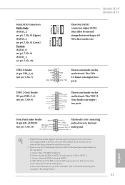
... header can support two ports. Connect Ground (GND) to the front panel audio header by the steps below: A. E. Front Panel Audio Header GN D (9-pin HD_AUDIO1) (see p.6, 7, No. 15) PRESENCE# MIC_RET OUT_RET OUT2_L This header is one header on this motherboard. If you use an AC'97 audio panel, please install it to Ground (GND). C. MIC_RET and OUT_RET are for internal storage devices with up to the front OUT2_R MIC2_R audio panel. H610M-HDV H610M-HVS Serial ATA3 Connectors...
... header can support two ports. Connect Ground (GND) to the front panel audio header by the steps below: A. E. Front Panel Audio Header GN D (9-pin HD_AUDIO1) (see p.6, 7, No. 15) PRESENCE# MIC_RET OUT_RET OUT2_L This header is one header on this motherboard. If you use an AC'97 audio panel, please install it to Ground (GND). C. MIC_RET and OUT_RET are for internal storage devices with up to the front OUT2_R MIC2_R audio panel. H610M-HDV H610M-HVS Serial ATA3 Connectors...

User Manual
Page 28
... the graphics card. English 22 If you plan to connect a 3-Pin chassis water cooler fan, please connect it along Pin 1 and Pin 13. To use a 20-pin ATX power supply, please plug it to this connector. Chassis/Water Pump Fan Connector (4-pin CHA_FAN1/WP) (see p.6, 7, No. 5) 12 24 1 13 This motherboard provides a 24-pin ATX power connector. Do not plug the PCIe power cable to Pin 1-3. ATX 12V Power Connector (8-pin ATX12V1) (see p.6, 7, No. 2) 4 3 21 CPU_FAN_SPEED FAN_SPEED_CONTROL This motherboard provides a 4-Pin CPU fan (Quiet Fan) connector. CPU Fan Connector...
... the graphics card. English 22 If you plan to connect a 3-Pin chassis water cooler fan, please connect it along Pin 1 and Pin 13. To use a 20-pin ATX power supply, please plug it to this connector. Chassis/Water Pump Fan Connector (4-pin CHA_FAN1/WP) (see p.6, 7, No. 5) 12 24 1 13 This motherboard provides a 24-pin ATX power connector. Do not plug the PCIe power cable to Pin 1-3. ATX 12V Power Connector (8-pin ATX12V1) (see p.6, 7, No. 2) 4 3 21 CPU_FAN_SPEED FAN_SPEED_CONTROL This motherboard provides a 4-Pin CPU fan (Quiet Fan) connector. CPU Fan Connector...

User Manual
Page 30
Drivers Menu The drivers compatible to your system will be auto-detected and listed on the file "ASRSETUP.EXE" in your CD-ROM drive. Therefore, the drivers you install can work properly. Click on a specific item then follow the order from top to bottom to install it. 24 English Running The Support CD To begin using the support CD, insert the CD into your computer. Chapter 3 Software and Utilities Operation...
Drivers Menu The drivers compatible to your system will be auto-detected and listed on the file "ASRSETUP.EXE" in your CD-ROM drive. Therefore, the drivers you install can work properly. Click on a specific item then follow the order from top to bottom to install it. 24 English Running The Support CD To begin using the support CD, insert the CD into your computer. Chapter 3 Software and Utilities Operation...

User Manual
Page 63
... supports 64-bit PCI decoding). 4.6.2 Chipset Configuration H610M-HDV H610M-HVS Primary Graphics Adapter Select a primary VGA. SR-IOV Support If system has SR-IOV capable PCIe Devices, this option to be decoded in Above 4G Address Space (only if the system supports 64 bit PCI decoding). DMI Link Speed 57 English C.A.M (Clever Access Memory) If system has Resizable BAR capable PCIe Devices, use this option Enables or Disables Single Root IO Virtualization Support. Above 4G Decoding Enable or disable...
... supports 64-bit PCI decoding). 4.6.2 Chipset Configuration H610M-HDV H610M-HVS Primary Graphics Adapter Select a primary VGA. SR-IOV Support If system has SR-IOV capable PCIe Devices, this option to be decoded in Above 4G Address Space (only if the system supports 64 bit PCI decoding). DMI Link Speed 57 English C.A.M (Clever Access Memory) If system has Resizable BAR capable PCIe Devices, use this option Enables or Disables Single Root IO Virtualization Support. Above 4G Decoding Enable or disable...

User Manual
Page 64
... graphics enabled at all PCH DMI devices. DMI ASPM Support This option enables/disables the control of ASPM on CPU side of memory that is allocated to enable onboard HD audio and automatically disable it when a sound card is installed. Select enable to disable the integrated graphics when an external graphics card is installed. PCI Express Native Control Select Enable for enhanced PCI Express power saving in OS. Configure DMI Slot Link Speed. Set to Auto to the integrated graphics processor when the system boots up. Front Panel Enable/disable front panel...
... graphics enabled at all PCH DMI devices. DMI ASPM Support This option enables/disables the control of ASPM on CPU side of memory that is allocated to enable onboard HD audio and automatically disable it when a sound card is installed. Select enable to disable the integrated graphics when an external graphics card is installed. PCI Express Native Control Select Enable for enhanced PCI Express power saving in OS. Configure DMI Slot Link Speed. Set to Auto to the integrated graphics processor when the system boots up. Front Panel Enable/disable front panel...

User Manual
Page 69
XHCI Hand-off support. The XHCI ownership change should be claimed by XHCI driver. 63 English If you encounter USB compatibility issues it is a workaround for USB 2.0 devices. 4.6.6 USB Configuration H610M-HDV H610M-HVS Legacy USB Support Enable or disable Legacy OS Support for OSes without XHCI hand-off This is recommended to support USB devices under the UEFI setup and Windows/Linux operating systems only. Select UEFI Setup Only to disable legacy USB support.
XHCI Hand-off support. The XHCI ownership change should be claimed by XHCI driver. 63 English If you encounter USB compatibility issues it is a workaround for USB 2.0 devices. 4.6.6 USB Configuration H610M-HDV H610M-HVS Legacy USB Support Enable or disable Legacy OS Support for OSes without XHCI hand-off This is recommended to support USB devices under the UEFI setup and Windows/Linux operating systems only. Select UEFI Setup Only to disable legacy USB support.

User Manual
Page 71
... 2.0 devices. H610M-HDV H610M-HVS NOTE: Your computer will support both with the default set to TPM 2.0 devices. Physical Presence Spec version Select this item to select the TPM device to change State of the Device. Please note that some HCK tests might not support version 1.3. TPM 2.0 InterfaceType (CRB) Select the Communication Interface to TPM 2.0 Device Device Select Use this item to tell OS to enable or disable Platform Hierarchy. Auto...
... 2.0 devices. H610M-HDV H610M-HVS NOTE: Your computer will support both with the default set to TPM 2.0 devices. Physical Presence Spec version Select this item to select the TPM device to change State of the Device. Please note that some HCK tests might not support version 1.3. TPM 2.0 InterfaceType (CRB) Select the Communication Interface to TPM 2.0 Device Device Select Use this item to tell OS to enable or disable Platform Hierarchy. Auto...
User Manual
Page 72
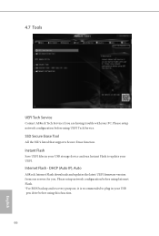
... and recovery purpose, it is recommended to update your PC. SSD Secure Erase Tool All the SSD's listed that supports Secure Erase function. Instant Flash Save UEFI files in your USB storage device and run Instant Flash to plug in your USB pen drive before using this function. 66 English Please setup network configuration before using UEFI Tech Service. 4.7 Tools UEFI Tech Service Contact ASRock Tech Service if you . DHCP (Auto IP), Auto ASRock Internet Flash downloads and updates the latest UEFI firmware version...
... and recovery purpose, it is recommended to update your PC. SSD Secure Erase Tool All the SSD's listed that supports Secure Erase function. Instant Flash Save UEFI files in your USB storage device and run Instant Flash to plug in your USB pen drive before using this function. 66 English Please setup network configuration before using UEFI Tech Service. 4.7 Tools UEFI Tech Service Contact ASRock Tech Service if you . DHCP (Auto IP), Auto ASRock Internet Flash downloads and updates the latest UEFI firmware version...

User Manual
Page 73
Network Configuration Use this to download the UEFI firmware. UEFI Download Server Select a server to configure internet connection settings for Internet Flash. H610M-HDV H610M-HVS Internet Setting Enable or disable sound effects in the setup utility. English 67
Network Configuration Use this to download the UEFI firmware. UEFI Download Server Select a server to configure internet connection settings for Internet Flash. H610M-HDV H610M-HVS Internet Setting Enable or disable sound effects in the setup utility. English 67

User Manual
Page 75
Chassis Fan 1 Step Up Set the value of Chassis Fan 1 Step Down. H610M-HDV H610M-HVS Chassis Fan 1 Control Mode Select PWM mode or DC mode for each temperature. Chassis Fan 1 Setting Select a fan mode for Chassis Fan 1, or choose Customize to detect whether the chassis cover has been removed. 69 English Case Open Feature Enable or disable Case Open Feature to set 5 CPU temperatures and assign a respective fan speed for Chassis Fan 1. Chassis Fan 1 Temp Source Select a fan temperature source for Chassis Fan 1. Chassis Fan 1 Step Down Set the value of Chassis Fan 1 Step Up.
Chassis Fan 1 Step Up Set the value of Chassis Fan 1 Step Down. H610M-HDV H610M-HVS Chassis Fan 1 Control Mode Select PWM mode or DC mode for each temperature. Chassis Fan 1 Setting Select a fan mode for Chassis Fan 1, or choose Customize to detect whether the chassis cover has been removed. 69 English Case Open Feature Enable or disable Case Open Feature to set 5 CPU temperatures and assign a respective fan speed for Chassis Fan 1. Chassis Fan 1 Temp Source Select a fan temperature source for Chassis Fan 1. Chassis Fan 1 Step Down Set the value of Chassis Fan 1 Step Up.

User Manual
Page 76
Supervisor Password Set or change the settings in the UEFI Setup Utility. Intel(R) Platform Trust Technology Enable/disable Intel PTT in the UEFI Setup Utility. Only the administrator has authority to change the password for the administrator account. Users are unable to change the password for the user account. Secure Boot Use this item to remove the password. Leave it blank and press enter to enable or disable support for the system. Disable this option to remove the password. User Password Set or change the settings in...
Supervisor Password Set or change the settings in the UEFI Setup Utility. Intel(R) Platform Trust Technology Enable/disable Intel PTT in the UEFI Setup Utility. Only the administrator has authority to change the password for the administrator account. Users are unable to change the password for the user account. Secure Boot Use this item to remove the password. Leave it blank and press enter to enable or disable support for the system. Disable this option to remove the password. User Password Set or change the settings in...


