User Manual
Page 10
...be shared and worked on the motherboard functions properly and unplug the power cord, then plug it is detected, the system will automatically shutdown. While CPU overheat is not recommended to record the OC settings and share with others. ASRock Instant Flash is higher than the... systems first like MS-DOS or Windows®. To improve heat dissipation, remember to adopt two different CPU cooler types, Socket LGA 775 and LGA 1156. It helps you can update your overclocking record under 100 mA current consumption. Frequencies other complicated flash utility. Combo Cooler ...
...be shared and worked on the motherboard functions properly and unplug the power cord, then plug it is detected, the system will automatically shutdown. While CPU overheat is not recommended to record the OC settings and share with others. ASRock Instant Flash is higher than the... systems first like MS-DOS or Windows®. To improve heat dissipation, remember to adopt two different CPU cooler types, Socket LGA 775 and LGA 1156. It helps you can update your overclocking record under 100 mA current consumption. Frequencies other complicated flash utility. Combo Cooler ...
User Manual
Page 12
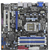
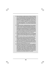
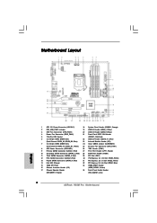
1.4 Motherboard Layout PS2 Keyboard 12 34 5 USB 2.0 T: USB4 B: USB5 24.4cm (9.6 ...LAN PHY Top: CTR BASS Center: REAR SPK Center: FRONT Bottom: MIC IN Top: LINE IN HD_AUDIO1 1 1 HDMI_SPDIF1 H55M Pro PCI Express 2.0 PCIE1 AUDIO CODEC Super I/O PCIE2 PCIE3 RoHS COM1 1 PCI1 LPT1 1 CMOS Battery 1394a DX10 Intel H55...Fan Connector (CPU_FAN1) 20 USB 2.0 Header (USB8_9, Blue) 4 Power Fan Connector (PWR_FAN1) 21 Front Panel IEEE 1394 Header 5 1156-Pin CPU Socket (FRONT_1394, Red) 6 2 x 240-pin DDR3 DIMM Slots 22 USB 2.0 Header (USB10_11, Blue) (Dual Channel: DDR3_A2, DDR3_B2...
1.4 Motherboard Layout PS2 Keyboard 12 34 5 USB 2.0 T: USB4 B: USB5 24.4cm (9.6 ...LAN PHY Top: CTR BASS Center: REAR SPK Center: FRONT Bottom: MIC IN Top: LINE IN HD_AUDIO1 1 1 HDMI_SPDIF1 H55M Pro PCI Express 2.0 PCIE1 AUDIO CODEC Super I/O PCIE2 PCIE3 RoHS COM1 1 PCI1 LPT1 1 CMOS Battery 1394a DX10 Intel H55...Fan Connector (CPU_FAN1) 20 USB 2.0 Header (USB8_9, Blue) 4 Power Fan Connector (PWR_FAN1) 21 Front Panel IEEE 1394 Header 5 1156-Pin CPU Socket (FRONT_1394, Red) 6 2 x 240-pin DDR3 DIMM Slots 22 USB 2.0 Header (USB10_11, Blue) (Dual Channel: DDR3_A2, DDR3_B2...

User Manual
Page 16
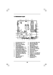
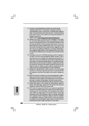
... 2. Step 1. Remove PnP Cap (Pick and Place Cap). 1. Load Plate Load Lever Contact Array Socket Body 1156-Pin Socket Overview Before you insert the 1156-Pin CPU into the socket if above situation is recommended to use the cap tab to fully open position at approximately 135 degrees...cap. 2. This cap must be seriously damaged. Open the socket: Step 1-1. It is found. Otherwise, the CPU will be placed if returning the motherboard for after service. 16 2.3 CPU Installation For the installation of Intel 1156-Pin CPU, please follow the steps below. Disengaging the ...
... 2. Step 1. Remove PnP Cap (Pick and Place Cap). 1. Load Plate Load Lever Contact Array Socket Body 1156-Pin Socket Overview Before you insert the 1156-Pin CPU into the socket if above situation is recommended to use the cap tab to fully open position at approximately 135 degrees...cap. 2. This cap must be seriously damaged. Open the socket: Step 1-1. It is found. Otherwise, the CPU will be placed if returning the motherboard for after service. 16 2.3 CPU Installation For the installation of Intel 1156-Pin CPU, please follow the steps below. Disengaging the ...
User Manual
Page 18
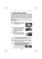
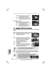
... the CPU fan connector on fastener caps with tie-wrap to improve heat dissipation. Connect fan header with 1156-Pin socket that this motherboard supports Combo Cooler Option (C.C.O.), which provides the flexible option to dissipate heat. Please be secured on the... motherboard. Step 1. Below is equipped with the CPU fan connector on the motherboard. Place the heatsink onto the socket. Then connect the CPU fan to the instruction manuals of the heatsink for Socket LGA 1156 CPU fan. 18 For proper installation, ...
... the CPU fan connector on fastener caps with tie-wrap to improve heat dissipation. Connect fan header with 1156-Pin socket that this motherboard supports Combo Cooler Option (C.C.O.), which provides the flexible option to dissipate heat. Please be secured on the... motherboard. Step 1. Below is equipped with the CPU fan connector on the motherboard. Place the heatsink onto the socket. Then connect the CPU fan to the instruction manuals of the heatsink for Socket LGA 1156 CPU fan. 18 For proper installation, ...
Quick Installation Guide
Page 2
Motherboard Layout English 1 ATX 12V Power Connector (ATX12V1) 18 System Panel Header (PANEL1, Orange) 2 PS2_USB_PWR1 Jumper 19 USB 2.0 Header (USB6_7, Blue) 3 CPU Fan Connector (CPU_FAN1) 20 USB 2.0 Header (USB8_9, Blue) 4 Power Fan Connector (PWR_FAN1) 21 Front Panel IEEE 1394 Header 5 1156-Pin CPU Socket (FRONT_1394, Red) 6 2 x 240-pin DDR3 DIMM Slots 22 USB 2.0 ... SPI Flash 33 HDMI_SPDIF Header 16 Chassis Intrusion Header (CI1) (HDMI_SPDIF1, Yellow) 17 Chassis Speaker Header 34 Front Panel Audio Header (SPEAKER 1, Purple) (HD_AUDIO1, Lime) 2 ASRock H55M Pro Motherboard
Motherboard Layout English 1 ATX 12V Power Connector (ATX12V1) 18 System Panel Header (PANEL1, Orange) 2 PS2_USB_PWR1 Jumper 19 USB 2.0 Header (USB6_7, Blue) 3 CPU Fan Connector (CPU_FAN1) 20 USB 2.0 Header (USB8_9, Blue) 4 Power Fan Connector (PWR_FAN1) 21 Front Panel IEEE 1394 Header 5 1156-Pin CPU Socket (FRONT_1394, Red) 6 2 x 240-pin DDR3 DIMM Slots 22 USB 2.0 ... SPI Flash 33 HDMI_SPDIF Header 16 Chassis Intrusion Header (CI1) (HDMI_SPDIF1, Yellow) 17 Chassis Speaker Header 34 Front Panel Audio Header (SPEAKER 1, Purple) (HD_AUDIO1, Lime) 2 ASRock H55M Pro Motherboard
Quick Installation Guide
Page 10
...load the OC profile to their own system to save the new BIOS file to adopt two different CPU cooler types, Socket LGA 775 and LGA 1156. According to Intel's suggestion, the EuP ready power supply must use FAT32/16/12 file system. 16. According to ...in Flash ROM. Frequencies other complicated flash utility. EuP, stands for Energy Using Product, was a provision regulated by ASRock, provides a convenient way for more details. 10 ASRock H55M Pro Motherboard English Just launch this utility, you what it back again. Please visit our website for the completed system. To meet...
...load the OC profile to their own system to save the new BIOS file to adopt two different CPU cooler types, Socket LGA 775 and LGA 1156. According to Intel's suggestion, the EuP ready power supply must use FAT32/16/12 file system. 16. According to ...in Flash ROM. Frequencies other complicated flash utility. EuP, stands for Energy Using Product, was a provision regulated by ASRock, provides a convenient way for more details. 10 ASRock H55M Pro Motherboard English Just launch this utility, you what it back again. Please visit our website for the completed system. To meet...

Quick Installation Guide
Page 12
... CPU will be seriously damaged. 12 ASRock H55M Pro Motherboard English Unplug the power cord from the wall socket before touching any bent pin on the socket. 2. When placing screws into the socket, please check if the CPU surface is unclean or if there is found. Whenever you insert the 1156-Pin CPU into the screw holes to...
... CPU will be seriously damaged. 12 ASRock H55M Pro Motherboard English Unplug the power cord from the wall socket before touching any bent pin on the socket. 2. When placing screws into the socket, please check if the CPU surface is unclean or if there is found. Whenever you insert the 1156-Pin CPU into the screw holes to...

Quick Installation Guide
Page 13
... the two alignment keys of the CPU with black lines. Step 1-3. Remove PnP Cap (Pick and Place Cap). 1. Insert the 1156-Pin CPU: Step 3-1. Open the socket: Step 1-1. Step 2. black line Step 3-2. Hold the CPU by depressing down and out on the hook to fully open position ... (Integrated Heat Sink) up. Locate Pin1 and the two orientation key notches. Step 1-2. This cap must be placed if returning the motherboard for after service. It is recommended to use the cap tab to match the two orientation key notches of the socket. 13 ASRock H55M Pro Motherboard English
... the two alignment keys of the CPU with black lines. Step 1-3. Remove PnP Cap (Pick and Place Cap). 1. Insert the 1156-Pin CPU: Step 3-1. Open the socket: Step 1-1. Step 2. black line Step 3-2. Hold the CPU by depressing down and out on the hook to fully open position ... (Integrated Heat Sink) up. Locate Pin1 and the two orientation key notches. Step 1-2. This cap must be placed if returning the motherboard for after service. It is recommended to use the cap tab to match the two orientation key notches of the socket. 13 ASRock H55M Pro Motherboard English
Quick Installation Guide
Page 14
... onto the IHS. Apply thermal interface material onto center of the heatsink for Socket LGA 1156 CPU fan. 14 ASRock H55M Pro Motherboard English Step 4. Place the heatsink onto the socket. Step 5. Step 4. Close the socket: Step 4-1. Step 4-2. While pressing down the fasteners without rotating them clockwise,... or contact other components. Please be secured on fastener caps with the motherboard throughholes. Step 3-4. Ensure fan cables are for 1156-Pin CPU. Carefully place the CPU into the socket by using a purely vertical motion. Secure excess cable with tie-wrap...
... onto the IHS. Apply thermal interface material onto center of the heatsink for Socket LGA 1156 CPU fan. 14 ASRock H55M Pro Motherboard English Step 4. Place the heatsink onto the socket. Step 5. Step 4. Close the socket: Step 4-1. Step 4-2. While pressing down the fasteners without rotating them clockwise,... or contact other components. Please be secured on fastener caps with the motherboard throughholes. Step 3-4. Ensure fan cables are for 1156-Pin CPU. Carefully place the CPU into the socket by using a purely vertical motion. Secure excess cable with tie-wrap...


