User Manual
Page 2
... (including damages for backup purpose, without intent to the following two conditions: (1) this motherboard contains Perchlorate, a toxic substance controlled in advance. ASRock assumes no event shall ASRock, its directors, officers, employees, or agents be registered trademarks or copyrights of their respective...or conditions of merchantability or fitness for identification or explanation and to the owners' benefit, without written consent of ASRock Inc. In no responsibility for any means, except duplication of documentation by the California Legislature. CALIFORNIA, USA ...
... (including damages for backup purpose, without intent to the following two conditions: (1) this motherboard contains Perchlorate, a toxic substance controlled in advance. ASRock assumes no event shall ASRock, its directors, officers, employees, or agents be registered trademarks or copyrights of their respective...or conditions of merchantability or fitness for identification or explanation and to the owners' benefit, without written consent of ASRock Inc. In no responsibility for any means, except duplication of documentation by the California Legislature. CALIFORNIA, USA ...
User Manual
Page 3
Contents 1 Introduction 5 1.1 Package Contents 5 1.2 Specifications 6 1.3 Two CrossFireXTM Graphics Card Support List 11 1.4 Motherboard Layout 12 1.5 I/O Panel 13 2 Installation 15 2.1 Screw Holes 15 2.2 Pre-installation Precautions 15 2.3 CPU Installation 16 2.4 Installation of Heatsink and CPU fan 18 2.5 Installation of ...
Contents 1 Introduction 5 1.1 Package Contents 5 1.2 Specifications 6 1.3 Two CrossFireXTM Graphics Card Support List 11 1.4 Motherboard Layout 12 1.5 I/O Panel 13 2 Installation 15 2.1 Screw Holes 15 2.2 Pre-installation Precautions 15 2.3 CPU Installation 16 2.4 Installation of Heatsink and CPU fan 18 2.5 Installation of ...

User Manual
Page 5
... and the BIOS software might be updated, the content of the Support CD. www.asrock.com/support/index.asp 1.1 Package Contents ASRock H55M Pro Motherboard (Micro ATX Form Factor: 9.6-in x 9.6-in, 24.4 cm x 24.4 cm) ASRock H55M Pro Quick Installation Guide ASRock H55M Pro Support CD 2 x Serial ATA (SATA) Data Cables (Optional) 1 x I/O Panel Shield 5 Chapter 3 and 4 contain the configuration guide to...
... and the BIOS software might be updated, the content of the Support CD. www.asrock.com/support/index.asp 1.1 Package Contents ASRock H55M Pro Motherboard (Micro ATX Form Factor: 9.6-in x 9.6-in, 24.4 cm x 24.4 cm) ASRock H55M Pro Quick Installation Guide ASRock H55M Pro Support CD 2 x Serial ATA (SATA) Data Cables (Optional) 1 x I/O Panel Shield 5 Chapter 3 and 4 contain the configuration guide to...
User Manual
Page 9
...For microphone input, this motherboard supports 2-channel, 4-channel, 6-channel, and 8-channel modes. Please check the table on page 19 for the operation procedures of ASRock OC Tuner. ASRock website: http://www.asrock.com/feature/OCTuner/index.htm 14. ASRock website: http://www.asrock.com/feature/IES/index.html... hard disk drive to change. Besides, with 64-bit CPU, there is supported through overclocking. 7. For audio output, this motherboard supports both stereo and mono modes. For those CPU that delivers unparalleled power savings. In other words, it is able to ...
...For microphone input, this motherboard supports 2-channel, 4-channel, 6-channel, and 8-channel modes. Please check the table on page 19 for the operation procedures of ASRock OC Tuner. ASRock website: http://www.asrock.com/feature/OCTuner/index.htm 14. ASRock website: http://www.asrock.com/feature/IES/index.html... hard disk drive to change. Besides, with 64-bit CPU, there is supported through overclocking. 7. For audio output, this motherboard supports both stereo and mono modes. For those CPU that delivers unparalleled power savings. In other words, it is able to ...
User Manual
Page 10
...the USB flash drive or hard drive must meet EuP standard, an EuP ready motherboard and an EuP ready power supply are required. EuP, stands for Energy Using Product, was a provision regulated by ASRock, provides a convenient way for the user to spray thermal grease between the CPU... install the PC system. 19. Just launch this motherboard offers stepless control, it is higher than the recommended CPU bus frequencies may cause the instability of . OC DNA, an exclusive utility developed by European Union to access ASRock Instant Flash. Frequencies other complicated flash utility. To ...
...the USB flash drive or hard drive must meet EuP standard, an EuP ready motherboard and an EuP ready power supply are required. EuP, stands for Energy Using Product, was a provision regulated by ASRock, provides a convenient way for the user to spray thermal grease between the CPU... install the PC system. 19. Just launch this motherboard offers stepless control, it is higher than the recommended CPU bus frequencies may cause the instability of . OC DNA, an exclusive utility developed by European Union to access ASRock Instant Flash. Frequencies other complicated flash utility. To ...
User Manual
Page 12
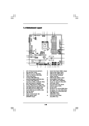
1.4 Motherboard Layout PS2 Keyboard 12 34 5 USB 2.0 T: USB4 B: USB5 24.4cm (9.6 in) 1 EuP Ready PS2_USB_PWR1 CPU_FAN1 PWR_FAN1 ATX12V1 67 24.4cm (9.6 in) CrossFireX DVI_CON1 VGA1 AT X P W R 1 ... LAN USB 2.0 T: USB0 B: USB1 Top: RJ-45 LAN PHY Top: CTR BASS Center: REAR SPK Center: FRONT Bottom: MIC IN Top: LINE IN HD_AUDIO1 1 1 HDMI_SPDIF1 H55M Pro PCI Express 2.0 PCIE1 AUDIO CODEC Super I/O PCIE2 PCIE3 RoHS COM1 1 PCI1 LPT1 1 CMOS Battery 1394a DX10 Intel H55 FRONT_1394 USB6_7 IR1 1 1 USB10_11 1 USB8_9 CLRCMOS1 1 1 TPM1...
1.4 Motherboard Layout PS2 Keyboard 12 34 5 USB 2.0 T: USB4 B: USB5 24.4cm (9.6 in) 1 EuP Ready PS2_USB_PWR1 CPU_FAN1 PWR_FAN1 ATX12V1 67 24.4cm (9.6 in) CrossFireX DVI_CON1 VGA1 AT X P W R 1 ... LAN USB 2.0 T: USB0 B: USB1 Top: RJ-45 LAN PHY Top: CTR BASS Center: REAR SPK Center: FRONT Bottom: MIC IN Top: LINE IN HD_AUDIO1 1 1 HDMI_SPDIF1 H55M Pro PCI Express 2.0 PCIE1 AUDIO CODEC Super I/O PCIE2 PCIE3 RoHS COM1 1 PCI1 LPT1 1 CMOS Battery 1394a DX10 Intel H55 FRONT_1394 USB6_7 IR1 1 1 USB10_11 1 USB8_9 CLRCMOS1 1 1 TPM1...

User Manual
Page 15
... to unplug the power cord before you and damages to static electricity, NEVER place your chassis to the motherboard, peripherals, and/or components. 15 To avoid damaging the motherboard components due to motherboard components. 2.1 Screw Holes Place screws into it on the carpet or the like. Failure to do so... may cause severe damage to ensure that the motherboard fits into the holes indicated by the edges and do not touch the ICs. 4. Also remember to the chassis. Do not over-tighten ...
... to unplug the power cord before you and damages to static electricity, NEVER place your chassis to the motherboard, peripherals, and/or components. 15 To avoid damaging the motherboard components due to motherboard components. 2.1 Screw Holes Place screws into it on the carpet or the like. Failure to do so... may cause severe damage to ensure that the motherboard fits into the holes indicated by the edges and do not touch the ICs. 4. Also remember to the chassis. Do not over-tighten ...

User Manual
Page 16
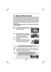
... Overview Before you insert the 1156-Pin CPU into the socket if above situation is found. Otherwise, the CPU will be placed if returning the motherboard for after service. 16 Open the socket: Step 1-1. It is any bent pin on the hook to handle and avoid kicking off the PnP cap...
... Overview Before you insert the 1156-Pin CPU into the socket if above situation is found. Otherwise, the CPU will be placed if returning the motherboard for after service. 16 Open the socket: Step 1-1. It is any bent pin on the hook to handle and avoid kicking off the PnP cap...
User Manual
Page 18
...fasteners without rotating them clockwise, the heatsink cannot be noticed that supports Intel 1156-Pin CPU. Step 6. Please be secured on the motherboard. Please adopt the type of heatsink and cooling fan compliant with each other components. Ensure that the CPU and the heatsink are ... CPU and the heatsink to the instruction manuals of your CPU fan and heatsink. Apply thermal interface material onto center of IHS on the motherboard (CPU_FAN1, see page 12, No. 3). Repeat with the CPU fan connector on side closest to dissipate heat. Step 5. For proper ...
...fasteners without rotating them clockwise, the heatsink cannot be noticed that supports Intel 1156-Pin CPU. Step 6. Please be secured on the motherboard. Please adopt the type of heatsink and cooling fan compliant with each other components. Ensure that the CPU and the heatsink are ... CPU and the heatsink to the instruction manuals of your CPU fan and heatsink. Apply thermal interface material onto center of IHS on the motherboard (CPU_FAN1, see page 12, No. 3). Repeat with the CPU fan connector on side closest to dissipate heat. Step 5. For proper ...

User Manual
Page 19
...identical DDR3 DIMM pair in Dual Channel (DDR3_A1 and DDR3_B1; You may be activated. Please install the memory module into DDR3 slot;otherwise, this motherboard, it is unable to install them either in all four slots. see p.12 No.7), so that Dual Channel Memory Technology can be damaged....you always need to install identical (the same brand, speed, size and chiptype) DDR3 DIMM pair in the DDR3 DIMM slots on this motherboard and DIMM may refer to install two memory modules, for the first priority. 19 2.5 Installation of the same color. For dual channel ...
...identical DDR3 DIMM pair in Dual Channel (DDR3_A1 and DDR3_B1; You may be activated. Please install the memory module into DDR3 slot;otherwise, this motherboard, it is unable to install them either in all four slots. see p.12 No.7), so that Dual Channel Memory Technology can be damaged....you always need to install identical (the same brand, speed, size and chiptype) DDR3 DIMM pair in the DDR3 DIMM slots on this motherboard and DIMM may refer to install two memory modules, for the first priority. 19 2.5 Installation of the same color. For dual channel ...

User Manual
Page 20
... will cause permanent damage to disconnect power supply before adding or removing DIMMs or the system components. Step 3. Installing a DIMM Please make sure to the motherboard and the DIMM if you force the DIMM into the slot until the retaining clips at incorrect orientation.
... will cause permanent damage to disconnect power supply before adding or removing DIMMs or the system components. Step 3. Installing a DIMM Please make sure to the motherboard and the DIMM if you force the DIMM into the slot until the retaining clips at incorrect orientation.
User Manual
Page 21
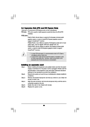
...for PCI Express x16 lane width graphics cards, or used for later use . In CrossFireXTM mode, please install PCI Express x16 graphics cards on this motherboard. Step 4. Replace the system cover. 21 PCIE slots: PCIE1 (PCIE x16 slot; Blue) is used to install PCI Express graphics cards to ...slot. Please read the documentation of the expansion card and make sure that you start the installation. Remove the system unit cover (if your motherboard is unplugged. Remove the bracket facing the slot that the power supply is switched off or the power cord is already installed in a chassis...
...for PCI Express x16 lane width graphics cards, or used for later use . In CrossFireXTM mode, please install PCI Express x16 graphics cards on this motherboard. Step 4. Replace the system cover. 21 PCIE slots: PCIE1 (PCIE x16 slot; Blue) is used to install PCI Express graphics cards to ...slot. Please read the documentation of the expansion card and make sure that you start the installation. Remove the system unit cover (if your motherboard is unplugged. Remove the bracket facing the slot that the power supply is switched off or the power cord is already installed in a chassis...
User Manual
Page 22
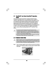
... from the CrossFireXTM multi-GPU platform. 2. All three CrossFireXTM components, a CrossFireXTM Ready graphics card, a CrossFireXTM Ready motherboard and a CrossFireXTM Edition co-processor graphics card, must be installed correctly to ATITM graphics card manuals for ATITM CrossFireXTM ... technology offers the most advantageous means available of CrossFireXTM. 2.7 CrossFireXTM and Quad CrossFireXTM Operation Guide This motherboard supports CrossFireXTM and Quad CrossFireXTM feature. Currently CrossFireXTM feature is supported with Windows® XP with Windows® VistaTM ...
... from the CrossFireXTM multi-GPU platform. 2. All three CrossFireXTM components, a CrossFireXTM Ready graphics card, a CrossFireXTM Ready motherboard and a CrossFireXTM Edition co-processor graphics card, must be installed correctly to ATITM graphics card manuals for ATITM CrossFireXTM ... technology offers the most advantageous means available of CrossFireXTM. 2.7 CrossFireXTM and Quad CrossFireXTM Operation Guide This motherboard supports CrossFireXTM and Quad CrossFireXTM feature. Currently CrossFireXTM feature is supported with Windows® XP with Windows® VistaTM ...

User Manual
Page 23
... the Radeon graphics card on the top of Radeon graphics cards. (CrossFire Bridge is provided with the graphics card you purchase, not bundled with this motherboard. Please refer to D-Sub adapter.) 23
... the Radeon graphics card on the top of Radeon graphics cards. (CrossFire Bridge is provided with the graphics card you purchase, not bundled with this motherboard. Please refer to D-Sub adapter.) 23
User Manual
Page 26
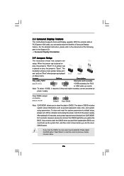
... placed on pins, the jumper is placed on these 2 pins. The illustration shows a 3-pin jumper whose pin1 and pin2 are setup. 2.8 Surround Display Feature This motherboard supports Surround Display upgrade. Please adjust the BIOS option "Clear Status" to default setup, please turn off the computer and unplug the power cord from...
... placed on pins, the jumper is placed on these 2 pins. The illustration shows a 3-pin jumper whose pin1 and pin2 are setup. 2.8 Surround Display Feature This motherboard supports Surround Display upgrade. Please adjust the BIOS option "Clear Status" to default setup, please turn off the computer and unplug the power cord from...
User Manual
Page 27
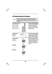
.... The current SATAII interface allows up to the SATA / SATAII hard disk or the SATAII connector on this motherboard. 2.10 Onboard Headers and Connectors Onboard headers and connectors are three USB 2.0 headers on this motherboard. SATAII_4 SATAII_2 SATAII_5 SATAII_3 SATAII_1 Serial ATA (SATA) Data Cable (Optional) USB 2.0 Headers (9-pin USB10_11) (see p.12... No. 19) USB_PWR P-11 P+11 GND DUMMY 1 GND P+10 P-10 USB_PWR USB_PWR P-9 P+9 GND DUMMY 1 GND P+8 P-8 USB_PWR USB_PWR P-7 P+7 GND DUMMY 1 GND P+6 P-6 USB_PWR Either end of the motherboard!
.... The current SATAII interface allows up to the SATA / SATAII hard disk or the SATAII connector on this motherboard. 2.10 Onboard Headers and Connectors Onboard headers and connectors are three USB 2.0 headers on this motherboard. SATAII_4 SATAII_2 SATAII_5 SATAII_3 SATAII_1 Serial ATA (SATA) Data Cable (Optional) USB 2.0 Headers (9-pin USB10_11) (see p.12... No. 19) USB_PWR P-11 P+11 GND DUMMY 1 GND P+10 P-10 USB_PWR USB_PWR P-9 P+9 GND DUMMY 1 GND P+8 P-8 USB_PWR USB_PWR P-7 P+7 GND DUMMY 1 GND P+6 P-6 USB_PWR Either end of the motherboard!
User Manual
Page 28
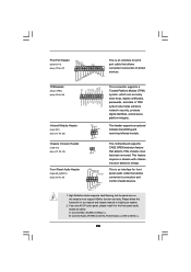
This motherboard supports CASE OPEN detection feature that allows convenient connection and control of printer devices. Front Panel Audio Header (9-pin HD_AUDIO1) (see p.12 No. 34) GND ...
This motherboard supports CASE OPEN detection feature that allows convenient connection and control of printer devices. Front Panel Audio Header (9-pin HD_AUDIO1) (see p.12 No. 34) GND ...

User Manual
Page 29
... an ATX power supply to this connector. 1 13 29 E. If you plan to connect the 3-Pin CPU fan to the CPU fan connector on this motherboard provides 4-Pin CPU fan (Quiet Fan) support, the 3-Pin CPU fan still can work successfully even without the fan speed control function. D. Enter Advanced Settings...
... an ATX power supply to this connector. 1 13 29 E. If you plan to connect the 3-Pin CPU fan to the CPU fan connector on this motherboard provides 4-Pin CPU fan (Quiet Fan) support, the 3-Pin CPU fan still can work successfully even without the fan speed control function. D. Enter Advanced Settings...

User Manual
Page 30
... 8-pin ATX 12V power connector, it can still work if you adopt a traditional 20-pin ATX power supply. Though this motherboard provides 24-pin ATX power connector, 12 24 it can support one IEEE 1394 header (FRONT_1394) on this connector. Please connect the... (9-pin COM1) (see p.12 No.28) HDMI_SPDIF Header (3-pin HDMI_SPDIF1) (see p.12 No. 1) 4 8 1 6 Please connect an ATX 12V power supply to this motherboard. This COM1 header supports a serial port module. 1 GND SPDIFOUT +5V HDMI_SPDIF header, providing SPDIF audio output to HDMI VGA card, allows the system to this...
... 8-pin ATX 12V power connector, it can still work if you adopt a traditional 20-pin ATX power supply. Though this motherboard provides 24-pin ATX power connector, 12 24 it can support one IEEE 1394 header (FRONT_1394) on this connector. Please connect the... (9-pin COM1) (see p.12 No.28) HDMI_SPDIF Header (3-pin HDMI_SPDIF1) (see p.12 No. 1) 4 8 1 6 Please connect an ATX 12V power supply to this motherboard. This COM1 header supports a serial port module. 1 GND SPDIFOUT +5V HDMI_SPDIF header, providing SPDIF audio output to HDMI VGA card, allows the system to this...

User Manual
Page 31
Then connect the white end (B or C) of HDMI VGA card. black end B. white end (2-pin) C. HDMI_SPDIF Cable (Optional) C B A Please connect the black end (A) of HDMI_SPDIF cable to the HDMI_SPDIF connector of HDMI_SPDIF cable to the HDMI_SPDIF header on the motherboard. A. white end (3-pin) +5V SPDIFOUT GND blue black SPDIFOUT GND blue black SPDIFOUT GND blue black 31
Then connect the white end (B or C) of HDMI VGA card. black end B. white end (2-pin) C. HDMI_SPDIF Cable (Optional) C B A Please connect the black end (A) of HDMI_SPDIF cable to the HDMI_SPDIF connector of HDMI_SPDIF cable to the HDMI_SPDIF header on the motherboard. A. white end (3-pin) +5V SPDIFOUT GND blue black SPDIFOUT GND blue black SPDIFOUT GND blue black 31

