
User Manual
Page 11
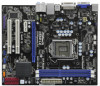
... Center: FRONT Bottom: MIC IN 1 HDMI_SPDIF1 1 HD_AUDIO1 H55M-LE PCI Express 2.0 PCIE1 EuP Ready DDR3 2600+ Gigabit LAN AUDIO CODEC Super I/O COM1 1 LPT1 1 PCIE2 RoHS PCI1 CI1 1 IR1 1 PCI2 CMOS Battery Intel 16Mb H55 BIOS SATAII_2 USB_PWR1 (PORT 6-9) 1 USB8_9 USB6_7 1 1 SATAII_4 CLRCMOS1 1 CHA_FAN1 PANEL1 PLED PWRBTN 1 HDLED RESET SPEAKER1 1 SATAII_3 SATAII_1 7 8 9 10 11 12...
... Center: FRONT Bottom: MIC IN 1 HDMI_SPDIF1 1 HD_AUDIO1 H55M-LE PCI Express 2.0 PCIE1 EuP Ready DDR3 2600+ Gigabit LAN AUDIO CODEC Super I/O COM1 1 LPT1 1 PCIE2 RoHS PCI1 CI1 1 IR1 1 PCI2 CMOS Battery Intel 16Mb H55 BIOS SATAII_2 USB_PWR1 (PORT 6-9) 1 USB8_9 USB6_7 1 1 SATAII_4 CLRCMOS1 1 CHA_FAN1 PANEL1 PLED PWRBTN 1 HDLED RESET SPEAKER1 1 SATAII_3 SATAII_1 7 8 9 10 11 12...

User Manual
Page 20
...the case open may be detected. Note: To select +5VSB, it requires 2 Amp and higher standby current provided by power supply. Please adjust the BIOS option "Clear Status" to clear the data in CMOS includes system setup information such as system password, date, time, and system setup parameters. Clear... wake up events. 2.7 Jumpers Setup The illustration shows how jumpers are "Short" when jumper cap is placed on these 2 pins. To clear and reset the system parameters to default setup, please turn off the computer and unplug the power cord from the power supply.
...the case open may be detected. Note: To select +5VSB, it requires 2 Amp and higher standby current provided by power supply. Please adjust the BIOS option "Clear Status" to clear the data in CMOS includes system setup information such as system password, date, time, and system setup parameters. Clear... wake up events. 2.7 Jumpers Setup The illustration shows how jumpers are "Short" when jumper cap is placed on these 2 pins. To clear and reset the system parameters to default setup, please turn off the computer and unplug the power cord from the power supply.

User Manual
Page 22
... an interface for HD audio panel only. E. Connect Mic_IN (MIC) to MIC2_L. This feature requires a chassis with chassis intrusion detection design. Enter BIOS Setup Utility. Infrared Module Header (5-pin IR1) (see p.11 No. 21) Chassis Intrusion Header (2-pin CI1) (see p.11 No. 14) PLED...+ PLEDPWRBTN# GND 1 DUMMY RESET# GND HDLEDHDLED+ 1 SPEAKER DUMMY DUMMY +5V This header accommodates several system front panel functions. This motherboard supports CASE OPEN detection feature that allows ...
... an interface for HD audio panel only. E. Connect Mic_IN (MIC) to MIC2_L. This feature requires a chassis with chassis intrusion detection design. Enter BIOS Setup Utility. Infrared Module Header (5-pin IR1) (see p.11 No. 21) Chassis Intrusion Header (2-pin CI1) (see p.11 No. 14) PLED...+ PLEDPWRBTN# GND 1 DUMMY RESET# GND HDLEDHDLED+ 1 SPEAKER DUMMY DUMMY +5V This header accommodates several system front panel functions. This motherboard supports CASE OPEN detection feature that allows ...

User Manual
Page 32
You may also restart by pressing the reset button on the system chassis. You may not exactly match what you start up the security features Exit To exit the current screen or the BIOS SETUP UTILITY Use < > key or < > key to choose among the selections on the menu bar, and then ...the following selections: Main To set up the system time/date information OC Tweaker To set up overclocking features Advanced To set up the advanced BIOS features H/W Monitor To display current hardware status Boot To set up the default system device to locate and load the Operating System Security To...
You may also restart by pressing the reset button on the system chassis. You may not exactly match what you start up the security features Exit To exit the current screen or the BIOS SETUP UTILITY Use < > key or < > key to choose among the selections on the menu bar, and then ...the following selections: Main To set up the system time/date information OC Tweaker To set up overclocking features Advanced To set up the advanced BIOS features H/W Monitor To display current hardware status Boot To set up the default system device to locate and load the Operating System Security To...

Quick Installation Guide
Page 16
...higher standby current provided by power supply. English 16 ASRock H55M-LE Motherboard USB_PWR1 (PORT 6-9) Short pin2, pin3 to enable (see p.2 No. 16) Default Clear CMOS Note: CLRCMOS1 allows you to clear the CMOS when you just finish updating the BIOS, you need to clear the data in CMOS ...pin jumper whose pin1 and pin2 are setup. When the jumper cap is placed on pins, the jumper is "Open". To clear and reset the system parameters to clear the record of previous chassis intrusion status. 2.5 Jumpers Setup The illustration shows how jumpers are "Short" when jumper...
...higher standby current provided by power supply. English 16 ASRock H55M-LE Motherboard USB_PWR1 (PORT 6-9) Short pin2, pin3 to enable (see p.2 No. 16) Default Clear CMOS Note: CLRCMOS1 allows you to clear the CMOS when you just finish updating the BIOS, you need to clear the data in CMOS ...pin jumper whose pin1 and pin2 are setup. When the jumper cap is placed on pins, the jumper is "Open". To clear and reset the system parameters to clear the record of previous chassis intrusion status. 2.5 Jumpers Setup The illustration shows how jumpers are "Short" when jumper...

Quick Installation Guide
Page 23
... the Power-On-Self-Test (POST) to display the menus. 23 ASRock H55M-LE Motherboard English For the detailed information about BIOS Setup, please refer to the User Manual (PDF file) contained in the Support CD to enter BIOS Setup utility; To begin using the Support CD, insert the CD into... the motherboard contains necessary drivers and useful utilities that came with its various sub-menus and to enter BIOS Setup after POST, please restart the system by pressing + + , or pressing the reset button on the file "ASSETUP.EXE" from the BIN folder in the Support CD. 4. When you...
... the Power-On-Self-Test (POST) to display the menus. 23 ASRock H55M-LE Motherboard English For the detailed information about BIOS Setup, please refer to the User Manual (PDF file) contained in the Support CD to enter BIOS Setup utility; To begin using the Support CD, insert the CD into... the motherboard contains necessary drivers and useful utilities that came with its various sub-menus and to enter BIOS Setup after POST, please restart the system by pressing + + , or pressing the reset button on the file "ASSETUP.EXE" from the BIN folder in the Support CD. 4. When you...


