User Manual
Page 10
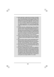
... spray thermal grease between the CPU and the heatsink when you can update your friends! EuP, stands for Energy Using Product, was a provision regulated by ASRock, provides a convenient way for the user to Intel's suggestion, the EuP ready power supply must use FAT32/16/12 file system. 15. To meet the... flash utility embedded in a few clicks without entering operating systems first like MS-DOS or Windows®. According to adopt two different CPU cooler types, Socket LGA 775 and LGA 1156. It helps you checking with your BIOS only in Flash ROM. The software name itself...
... spray thermal grease between the CPU and the heatsink when you can update your friends! EuP, stands for Energy Using Product, was a provision regulated by ASRock, provides a convenient way for the user to Intel's suggestion, the EuP ready power supply must use FAT32/16/12 file system. 15. To meet the... flash utility embedded in a few clicks without entering operating systems first like MS-DOS or Windows®. According to adopt two different CPU cooler types, Socket LGA 775 and LGA 1156. It helps you checking with your BIOS only in Flash ROM. The software name itself...

User Manual
Page 11
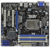
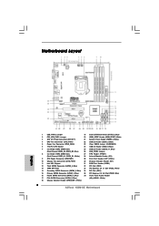
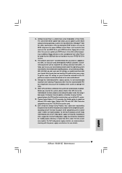
...USB1 Top: RJ-45 Top: LINE IN Center: FRONT Bottom: MIC IN LAN PHY 1 HD_AUDIO1 RoHS AUDIO CODEC Super I/O COM1 1 LPT1 1 CHA_FAN1 H55M-GE PCI Express 2.0 PCIE1 Designed in Taipei DDR3 2600+ PCI1 PCIE2 CMOS Battery ErP/EuP Ready PCI2 CLRCMOS1 1 CI1 1 IR1 1 TPMS1 1 USB_PWR3 1 USB10_11...) 4 CPU Fan Connector (CPU_FAN1) 22 USB 2.0 Header (USB6_7, Blue) 5 Power Fan Connector (PWR_FAN1) 23 Clear CMOS Jumper (CLRCMOS1) 6 1156-Pin CPU Socket 24 USB 2.0 Header (USB8_9, Blue) 7 2 x 240-pin DDR3 DIMM Slots 25 USB 2.0 Header (USB10_11, Blue) (Dual Channel: DDR3_A2, DDR3_B2, Blue)...
...USB1 Top: RJ-45 Top: LINE IN Center: FRONT Bottom: MIC IN LAN PHY 1 HD_AUDIO1 RoHS AUDIO CODEC Super I/O COM1 1 LPT1 1 CHA_FAN1 H55M-GE PCI Express 2.0 PCIE1 Designed in Taipei DDR3 2600+ PCI1 PCIE2 CMOS Battery ErP/EuP Ready PCI2 CLRCMOS1 1 CI1 1 IR1 1 TPMS1 1 USB_PWR3 1 USB10_11...) 4 CPU Fan Connector (CPU_FAN1) 22 USB 2.0 Header (USB6_7, Blue) 5 Power Fan Connector (PWR_FAN1) 23 Clear CMOS Jumper (CLRCMOS1) 6 1156-Pin CPU Socket 24 USB 2.0 Header (USB8_9, Blue) 7 2 x 240-pin DDR3 DIMM Slots 25 USB 2.0 Header (USB10_11, Blue) (Dual Channel: DDR3_A2, DDR3_B2, Blue)...
User Manual
Page 13
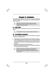
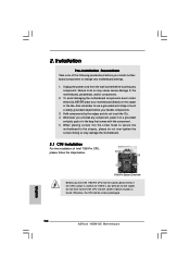
... components. 13 Make sure to static electricity, NEVER place your chassis to do not touch the ICs. 4. Chapter 2: Installation This is detached from the wall socket before you install motherboard components or change any component, ensure that comes with the component.
... components. 13 Make sure to static electricity, NEVER place your chassis to do not touch the ICs. 4. Chapter 2: Installation This is detached from the wall socket before you install motherboard components or change any component, ensure that comes with the component.

User Manual
Page 14
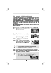
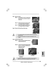
... Intel 1156-Pin CPU, please follow the steps below. Remove PnP Cap (Pick and Place Cap). 1. Do not force to insert the CPU into the socket, please check if the CPU surface is unclean or if there is any bent pin on the hook to fully open position at approximately 100... degrees. Disengaging the lever by depressing down and out on the socket. Rotate the load plate to clear retention tab. It is found. Rotate the load lever to handle and avoid kicking off the PnP cap. 2. This...
... Intel 1156-Pin CPU, please follow the steps below. Remove PnP Cap (Pick and Place Cap). 1. Do not force to insert the CPU into the socket, please check if the CPU surface is unclean or if there is any bent pin on the hook to fully open position at approximately 100... degrees. Disengaging the lever by depressing down and out on the socket. Rotate the load plate to clear retention tab. It is found. Rotate the load lever to handle and avoid kicking off the PnP cap. 2. This...

User Manual
Page 15
...Pin CPU: Step 3-1. Hold the CPU by using a purely vertical motion. Step 3-3. Carefully place the CPU into the socket by the edge where is within the socket and properly mated to match the two orientation key notches of the CPU with black line. Verify that the CPU is ... Step 3. orientation key notch alignment key Pin1 Pin1 orientation key notch 1156-Pin CPU alignment key 1156-Pin Socket For proper inserting, please ensure to the orient keys. Close the socket: Step 4-1. black line Step 3-2. Locate Pin1 and the two orientation key notches. Rotate the load plate ...
...Pin CPU: Step 3-1. Hold the CPU by using a purely vertical motion. Step 3-3. Carefully place the CPU into the socket by the edge where is within the socket and properly mated to match the two orientation key notches of the CPU with black line. Verify that the CPU is ... Step 3. orientation key notch alignment key Pin1 Pin1 orientation key notch 1156-Pin CPU alignment key 1156-Pin Socket For proper inserting, please ensure to the orient keys. Close the socket: Step 4-1. black line Step 3-2. Locate Pin1 and the two orientation key notches. Rotate the load plate ...
User Manual
Page 16
... Option (C.C.O.), which provides the flexible option to adopt two different CPU cooler types, Socket LGA 775 and LGA 1156. Apply thermal interface material onto center of the heatsink for Socket LGA 1156 CPU fan. 16 Before you installed the heatsink, you press down on... fastener caps with remaining fasteners. Below is equipped with each other components. Place the heatsink onto the socket. Step 5. The white throughholes are oriented on the motherboard (CPU_FAN1, see page 11, No. 4). Apply Thermal Interface Material Step 2. ...
... Option (C.C.O.), which provides the flexible option to adopt two different CPU cooler types, Socket LGA 775 and LGA 1156. Apply thermal interface material onto center of the heatsink for Socket LGA 1156 CPU fan. 16 Before you installed the heatsink, you press down on... fastener caps with remaining fasteners. Below is equipped with each other components. Place the heatsink onto the socket. Step 5. The white throughholes are oriented on the motherboard (CPU_FAN1, see page 11, No. 4). Apply Thermal Interface Material Step 2. ...
Quick Installation Guide
Page 2
... Panel Header (PANEL1, White) 4 CPU Fan Connector (CPU_FAN1) 22 USB 2.0 Header (USB6_7, Blue) 5 Power Fan Connector (PWR_FAN1) 23 Clear CMOS Jumper (CLRCMOS1) 6 1156-Pin CPU Socket 24 USB 2.0 Header (USB8_9, Blue) 7 2 x 240-pin DDR3 DIMM Slots 25 USB 2.0 Header (USB10_11, Blue) (Dual Channel: DDR3_A2, DDR3_B2, Blue) 26 USB_PWR3 Jumper 8 2 x 240-pin...) 16 Fourth SATAII Connector (SATAII_4, Blue) 36 Front Panel Audio Header 17 Fifth SATAII Connector (SATAII_5, Blue) (HD_AUDIO1, White) 18 Chassis Speaker Header (SPEAKER 1, White) 2 ASRock H55M-GE Motherboard
... Panel Header (PANEL1, White) 4 CPU Fan Connector (CPU_FAN1) 22 USB 2.0 Header (USB6_7, Blue) 5 Power Fan Connector (PWR_FAN1) 23 Clear CMOS Jumper (CLRCMOS1) 6 1156-Pin CPU Socket 24 USB 2.0 Header (USB8_9, Blue) 7 2 x 240-pin DDR3 DIMM Slots 25 USB 2.0 Header (USB10_11, Blue) (Dual Channel: DDR3_A2, DDR3_B2, Blue) 26 USB_PWR3 Jumper 8 2 x 240-pin...) 16 Fourth SATAII Connector (SATAII_4, Blue) 36 Front Panel Audio Header 17 Fifth SATAII Connector (SATAII_5, Blue) (HD_AUDIO1, White) 18 Chassis Speaker Header (SPEAKER 1, White) 2 ASRock H55M-GE Motherboard
Quick Installation Guide
Page 9
... system and simplifies the complicated recording process of 5v standby power efficiency is not recommended to define the power consumption for more details. 9 ASRock H55M-GE Motherboard English 14. Please be used. 19. It helps you resume the system, please check if the CPU fan on the same motherboard... in a few clicks without entering operating systems first like MS-DOS or Windows®. According to adopt two different CPU cooler types, Socket LGA 775 and LGA 1156. For EuP ready power supply selection, we recommend you can be noted that the OC profile can save ...
... system and simplifies the complicated recording process of 5v standby power efficiency is not recommended to define the power consumption for more details. 9 ASRock H55M-GE Motherboard English 14. Please be used. 19. It helps you resume the system, please check if the CPU fan on the same motherboard... in a few clicks without entering operating systems first like MS-DOS or Windows®. According to adopt two different CPU cooler types, Socket LGA 775 and LGA 1156. For EuP ready power supply selection, we recommend you can be noted that the OC profile can save ...
Quick Installation Guide
Page 10
...component. 5. Whenever you insert the 1156-Pin CPU into the socket, please check if the CPU surface is unclean or if there is found. Otherwise, the CPU will be seriously damaged. 10 ASRock H55M-GE Motherboard English Hold components by the edges and do so may damage... the motherboard. 2.1 CPU Installation For the installation of the following precautions before touching any motherboard settings. 1. Unplug the power cord from the wall socket before you handle components....
...component. 5. Whenever you insert the 1156-Pin CPU into the socket, please check if the CPU surface is unclean or if there is found. Otherwise, the CPU will be seriously damaged. 10 ASRock H55M-GE Motherboard English Hold components by the edges and do so may damage... the motherboard. 2.1 CPU Installation For the installation of the following precautions before touching any motherboard settings. 1. Unplug the power cord from the wall socket before you handle components....
Quick Installation Guide
Page 11
... cap. 2. Rotate the load plate to match the two orientation key notches of the CPU with the two alignment keys of the socket. 11 ASRock H55M-GE Motherboard English Step 3. Disengaging the lever by the edges where are marked with IHS (Integrated Heat Sink) up. Step 1-2. Step... 2. orientation key notch alignment key Pin1 Pin1 orientation key notch alignment key 1156-Pin Socket 1156-Pin CPU For proper inserting, please ensure...
... cap. 2. Rotate the load plate to match the two orientation key notches of the CPU with the two alignment keys of the socket. 11 ASRock H55M-GE Motherboard English Step 3. Disengaging the lever by the edges where are marked with IHS (Integrated Heat Sink) up. Step 1-2. Step... 2. orientation key notch alignment key Pin1 Pin1 orientation key notch alignment key 1156-Pin Socket 1156-Pin CPU For proper inserting, please ensure...

Quick Installation Guide
Page 12
... which provides the flexible option to illustrate the installation of IHS on the socket surface. Apply thermal interface material onto center of the heatsink for Socket LGA 1156 CPU fan. 12 ASRock H55M-GE Motherboard English Step 2. Ensure fan cables are for 1156-Pin CPU. Carefully ...place the CPU into the socket by using a purely vertical motion. Step 1. Step 4. Step 4-2. Please...
... which provides the flexible option to illustrate the installation of IHS on the socket surface. Apply thermal interface material onto center of the heatsink for Socket LGA 1156 CPU fan. 12 ASRock H55M-GE Motherboard English Step 2. Ensure fan cables are for 1156-Pin CPU. Carefully ...place the CPU into the socket by using a purely vertical motion. Step 1. Step 4. Step 4-2. Please...