
User Manual
Page 2
...but not limited to the implied warranties or conditions of the FCC Rules. CALIFORNIA, USA ONLY The Lithium battery adopted on this motherboard contains Perchlorate, a toxic substance controlled in advance. Copyright Notice: No part of this manual may be liable for any indirect,... or copyrights of any errors or omissions that may apply, see www.dtsc.ca.gov/hazardouswaste/perchlorate" ASRock Website: http://www.asrock.com 2 ASRock assumes no event shall ASRock, its directors, officers, employees, or agents be reproduced, transcribed, transmitted, or translated in any language...
...but not limited to the implied warranties or conditions of the FCC Rules. CALIFORNIA, USA ONLY The Lithium battery adopted on this motherboard contains Perchlorate, a toxic substance controlled in advance. Copyright Notice: No part of this manual may be liable for any indirect,... or copyrights of any errors or omissions that may apply, see www.dtsc.ca.gov/hazardouswaste/perchlorate" ASRock Website: http://www.asrock.com 2 ASRock assumes no event shall ASRock, its directors, officers, employees, or agents be reproduced, transcribed, transmitted, or translated in any language...

User Manual
Page 3
Contents 1 Introduction 5 1.1 Package Contents 5 1.2 Specifications 6 1.3 Two CrossFireXTM Graphics Card Support List 11 1.4 Motherboard Layout 12 1.5 I/O Panel 13 2 Installation 15 2.1 Screw Holes 15 2.2 Pre-installation Precautions 15 2.3 CPU Installation 16 2.4 Installation of Heatsink and CPU fan 18 2.5 Installation of ...
Contents 1 Introduction 5 1.1 Package Contents 5 1.2 Specifications 6 1.3 Two CrossFireXTM Graphics Card Support List 11 1.4 Motherboard Layout 12 1.5 I/O Panel 13 2 Installation 15 2.1 Screw Holes 15 2.2 Pre-installation Precautions 15 2.3 CPU Installation 16 2.4 Installation of Heatsink and CPU fan 18 2.5 Installation of ...
User Manual
Page 5
... If you for specific information about the model you are using. www.asrock.com/support/index.asp 1.1 Package Contents ASRock H55DE3 Motherboard (ATX Form Factor: 12.0-in x 8.3-in, 30.5 cm x 21.1 cm) ASRock H55DE3 Quick Installation Guide ASRock H55DE3 Support CD 2 x Serial ATA (SATA) Data Cables (Optional) 1 x I/O Panel Shield 5 In this manual occur, the updated version will be...
... If you for specific information about the model you are using. www.asrock.com/support/index.asp 1.1 Package Contents ASRock H55DE3 Motherboard (ATX Form Factor: 12.0-in x 8.3-in, 30.5 cm x 21.1 cm) ASRock H55DE3 Quick Installation Guide ASRock H55DE3 Support CD 2 x Serial ATA (SATA) Data Cables (Optional) 1 x I/O Panel Shield 5 In this manual occur, the updated version will be...

User Manual
Page 9
This motherboard supports Untied Overclocking Technology. For those CPU that delivers unparalleled power savings. Please check Intel® website for system usage under Windows® 7 / VistaTM / XP. Besides, with 64-bit CPU, there is a user-friendly ASRock overclocking tool which allows ... VistaTM 64-bit / VistaTM / XP 64-bit / XP SP1 or SP2. 13. HBR is supported through overclocking. 7. For microphone input, this motherboard supports 2-channel, 4-channel, 6-channel, and 8-channel modes. Please check the table on page 37 for proper connection. 11. Before installing SATAII hard...
This motherboard supports Untied Overclocking Technology. For those CPU that delivers unparalleled power savings. Please check Intel® website for system usage under Windows® 7 / VistaTM / XP. Besides, with 64-bit CPU, there is a user-friendly ASRock overclocking tool which allows ... VistaTM 64-bit / VistaTM / XP 64-bit / XP SP1 or SP2. 13. HBR is supported through overclocking. 7. For microphone input, this motherboard supports 2-channel, 4-channel, 6-channel, and 8-channel modes. Please check the table on page 37 for proper connection. 11. Before installing SATAII hard...

User Manual
Page 10
...standby power efficiency is not recommended to get the same OC settings as a profile and share with others. ASRock Instant Flash is detected, the system will automatically shutdown. With this motherboard offers stepless control, it back again. While CPU overheat is a BIOS flash utility embedded in a few ... settings as yours! OC DNA, an exclusive utility developed by European Union to access ASRock Instant Flash. With OC DNA, you resume the system, please check if the CPU fan on the same motherboard. 17. Although this utility, you can update your USB flash drive, floppy disk...
...standby power efficiency is not recommended to get the same OC settings as a profile and share with others. ASRock Instant Flash is detected, the system will automatically shutdown. With this motherboard offers stepless control, it back again. While CPU overheat is a BIOS flash utility embedded in a few ... settings as yours! OC DNA, an exclusive utility developed by European Union to access ASRock Instant Flash. With OC DNA, you resume the system, please check if the CPU fan on the same motherboard. 17. Although this utility, you can update your USB flash drive, floppy disk...

User Manual
Page 12
1.4 Motherboard Layout 12 3 4 21.1cm (8.3 in) USB 2.0 T: USB4 B: USB5 1 PS2_USB_PWR1 CPU_FAN1 ATX12V1 PS2 Keyboard 56 DDR3_A2 (64 bit, 240-pin module) DDR3_A1 (64 bit, 240-pin ... 27 Bottom: Optical SPDIF USB 2.0 T: USB0 B: USB1 Top: RJ-45 Top: CTR BASS Center: REAR SPK Bottom: MIC IN Center: FRONT PWR_FAN1 Top: LINE IN H55DE3 PCIE1 DDR3 2600+ Dual Channel DX10 LAN PHY PCIE2 PCI Express 2.0 16Mb CrossFireX BIOS PCIE3 Intel H55 Super I/O AUDIO CODEC 1 HD_AUDIO1 HDMI_SPDIF1 COM1 1 1 PCIE4 PCI1...
1.4 Motherboard Layout 12 3 4 21.1cm (8.3 in) USB 2.0 T: USB4 B: USB5 1 PS2_USB_PWR1 CPU_FAN1 ATX12V1 PS2 Keyboard 56 DDR3_A2 (64 bit, 240-pin module) DDR3_A1 (64 bit, 240-pin ... 27 Bottom: Optical SPDIF USB 2.0 T: USB0 B: USB1 Top: RJ-45 Top: CTR BASS Center: REAR SPK Bottom: MIC IN Center: FRONT PWR_FAN1 Top: LINE IN H55DE3 PCIE1 DDR3 2600+ Dual Channel DX10 LAN PHY PCIE2 PCI Express 2.0 16Mb CrossFireX BIOS PCIE3 Intel H55 Super I/O AUDIO CODEC 1 HD_AUDIO1 HDMI_SPDIF1 COM1 1 1 PCIE4 PCI1...

User Manual
Page 15
...component, ensure that the power is switched off or the power cord is an ATX form factor (12.0" x 8.3", 30.5 x 21.1 cm) motherboard. Do not over-tighten the screws! Before you handle components. 3. Failure to ensure that comes with the component. Also remember to unplug the ...power cord before installing or removing the motherboard. Before you and damages to the chassis. Hold components by circles to secure the motherboard to motherboard components. 2.1 Screw Holes Place screws into it on the carpet or the like. Unplug...
...component, ensure that the power is switched off or the power cord is an ATX form factor (12.0" x 8.3", 30.5 x 21.1 cm) motherboard. Do not over-tighten the screws! Before you handle components. 3. Failure to ensure that comes with the component. Also remember to unplug the ...power cord before installing or removing the motherboard. Before you and damages to the chassis. Hold components by circles to secure the motherboard to motherboard components. 2.1 Screw Holes Place screws into it on the carpet or the like. Unplug...
User Manual
Page 16
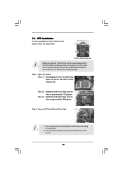
... recommended to use the cap tab to fully open position at approximately 100 degrees. Step 1. Step 2. Otherwise, the CPU will be placed if returning the motherboard for after service. 16 Rotate the load plate to handle and avoid kicking off the PnP cap. 2. Rotate the load lever to clear retention tab...
... recommended to use the cap tab to fully open position at approximately 100 degrees. Step 1. Step 2. Otherwise, the CPU will be placed if returning the motherboard for after service. 16 Rotate the load plate to handle and avoid kicking off the PnP cap. 2. Rotate the load lever to clear retention tab...
User Manual
Page 18
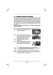
... Material Step 2. Step 6. Align fasteners with the CPU fan connector on side closest to dissipate heat. Connect fan header with the motherboard throughholes. Step 4. Repeat with remaining fasteners. Secure excess cable with tie-wrap to illustrate the installation of the heatsink for 1156-Pin... CPU. Step 3. Below is equipped with 1156-Pin socket that the CPU and the heatsink are oriented on the motherboard. Rotate the fastener clockwise, then press down the fasteners without rotating them clockwise, the heatsink cannot be secured on side...
... Material Step 2. Step 6. Align fasteners with the CPU fan connector on side closest to dissipate heat. Connect fan header with the motherboard throughholes. Step 4. Repeat with remaining fasteners. Secure excess cable with tie-wrap to illustrate the installation of the heatsink for 1156-Pin... CPU. Step 3. Below is equipped with 1156-Pin socket that the CPU and the heatsink are oriented on the motherboard. Rotate the fastener clockwise, then press down the fasteners without rotating them clockwise, the heatsink cannot be secured on side...

User Manual
Page 19
...Blue Slot) (White Slot) (1) - If only one memory module or three memory modules are installed in the DDR3 DIMM slots on this motherboard and DIMM may refer to install four DDR3 DIMMs for dual channel configuration, and please install identical DDR3 DIMMs in the slots of the same... DDR3 DIMMs in the slots of the same color. white slots; If you have to activate the Dual Channel Memory Technology. 3. This motherboard also allows you always need to install them either in Dual Channel (DDR3_A1 and DDR3_B1; For dual channel configuration, you to the Dual ...
...Blue Slot) (White Slot) (1) - If only one memory module or three memory modules are installed in the DDR3 DIMM slots on this motherboard and DIMM may refer to install four DDR3 DIMMs for dual channel configuration, and please install identical DDR3 DIMMs in the slots of the same... DDR3 DIMMs in the slots of the same color. white slots; If you have to activate the Dual Channel Memory Technology. 3. This motherboard also allows you always need to install them either in Dual Channel (DDR3_A1 and DDR3_B1; For dual channel configuration, you to the Dual ...

User Manual
Page 20
Installing a DIMM Please make sure to the motherboard and the DIMM if you force the DIMM into the slot until the retaining clips at incorrect orientation. Align a DIMM on the slot such that ...
Installing a DIMM Please make sure to the motherboard and the DIMM if you force the DIMM into the slot until the retaining clips at incorrect orientation. Align a DIMM on the slot such that ...

User Manual
Page 21
...bandwidth while PCIE4 slot will work at x4 bandwidth. 3. Step 3. Step 4. PCIE2 (PCIE x16 slot; Remove the system unit cover (if your motherboard is unplugged. Remove the bracket facing the slot that have the 32-bit PCI interface. Step 6. PCIE4 (PCIE x16 slot; Before installing the ... graphics cards to use . Installing an expansion card Step 1. Step 2. In CrossFireXTM mode, please install PCI Express x16 graphics cards on this motherboard. Align the card connector with x1 lane width cards, such as Gigabit LAN card, SATA2 card, etc. Step 5. If you want PCIE4 ...
...bandwidth while PCIE4 slot will work at x4 bandwidth. 3. Step 3. Step 4. PCIE2 (PCIE x16 slot; Remove the system unit cover (if your motherboard is unplugged. Remove the bracket facing the slot that have the 32-bit PCI interface. Step 6. PCIE4 (PCIE x16 slot; Before installing the ... graphics cards to use . Installing an expansion card Step 1. Step 2. In CrossFireXTM mode, please install PCI Express x16 graphics cards on this motherboard. Align the card connector with x1 lane width cards, such as Gigabit LAN card, SATA2 card, etc. Step 5. If you want PCIE4 ...

User Manual
Page 22
... the example graphics card. Please check AMD website for detailed installation guide. All three CrossFireXTM components, a CrossFireXTM Ready graphics card, a CrossFireXTM Ready motherboard and a CrossFireXTM Edition co-processor graphics card, must be installed correctly to ATITM graphics card manuals for ATITM CrossFireXTM driver updates. 1. For other ...Currently CrossFireXTM feature is supported with Windows® XP with Windows® VistaTM / 7 OS only. 2.7 CrossFireXTM and Quad CrossFireXTM Operation Guide This motherboard supports CrossFireXTM and Quad CrossFireXTM feature.
... the example graphics card. Please check AMD website for detailed installation guide. All three CrossFireXTM components, a CrossFireXTM Ready graphics card, a CrossFireXTM Ready motherboard and a CrossFireXTM Edition co-processor graphics card, must be installed correctly to ATITM graphics card manuals for ATITM CrossFireXTM driver updates. 1. For other ...Currently CrossFireXTM feature is supported with Windows® XP with Windows® VistaTM / 7 OS only. 2.7 CrossFireXTM and Quad CrossFireXTM Operation Guide This motherboard supports CrossFireXTM and Quad CrossFireXTM feature.

User Manual
Page 23
... the Radeon graphics card on the top of Radeon graphics cards. (CrossFire Bridge is provided with the graphics card you purchase, not bundled with this motherboard. Step 2.
... the Radeon graphics card on the top of Radeon graphics cards. (CrossFire Bridge is provided with the graphics card you purchase, not bundled with this motherboard. Step 2.

User Manual
Page 26
... or USB wake up the system first, and then shut it requires 2 Amp and higher standby current provided by power supply. 2.8 Surround Display Feature This motherboard supports Surround Display upgrade. When the jumper cap is "Open". To clear and reset the system parameters to clear the record of Surround Display feature...
... or USB wake up the system first, and then shut it requires 2 Amp and higher standby current provided by power supply. 2.8 Surround Display Feature This motherboard supports Surround Display upgrade. When the jumper cap is "Open". To clear and reset the system parameters to clear the record of Surround Display feature...

User Manual
Page 27
...1 GND P+8 P-8 USB_PWR USB_PWR P-7 P+7 GND DUMMY 1 GND P+6 P-6 USB_PWR Either end of the motherboard! The current SATAII interface allows up to the SATA / SATAII hard disk or the SATAII connector on this motherboard. Besides four default USB 2.0 ports on the I/O panel, there are NOT jumpers. Each USB 2.0 ... to 3.0 Gb/s data transfer rate. 2.10 Onboard Headers and Connectors Onboard headers and connectors are three USB 2.0 headers on this motherboard. Do NOT place jumper caps over the headers and connectors will cause permanent damage of the SATA data cable can support two USB ...
...1 GND P+8 P-8 USB_PWR USB_PWR P-7 P+7 GND DUMMY 1 GND P+6 P-6 USB_PWR Either end of the motherboard! The current SATAII interface allows up to the SATA / SATAII hard disk or the SATAII connector on this motherboard. Besides four default USB 2.0 ports on the I/O panel, there are NOT jumpers. Each USB 2.0 ... to 3.0 Gb/s data transfer rate. 2.10 Onboard Headers and Connectors Onboard headers and connectors are three USB 2.0 headers on this motherboard. Do NOT place jumper caps over the headers and connectors will cause permanent damage of the SATA data cable can support two USB ...

User Manual
Page 28
...-pin TPM1) (see p.12 No. 17) IRTX +5VSB DUMMY 1 GND IRRX 1 GND Signal This header supports an optional wireless transmitting and receiving infrared module. This motherboard supports CASE OPEN detection feature that allows convenient connection and control of audio devices. 1. Connect Mic_IN (MIC) to connect them for front panel audio cable...
...-pin TPM1) (see p.12 No. 17) IRTX +5VSB DUMMY 1 GND IRRX 1 GND Signal This header supports an optional wireless transmitting and receiving infrared module. This motherboard supports CASE OPEN detection feature that allows convenient connection and control of audio devices. 1. Connect Mic_IN (MIC) to connect them for front panel audio cable...

User Manual
Page 29
...ATX power supply, please plug your power supply along with Pin 1 and Pin 13. 20-Pin ATX Power Supply Installation 1 13 29 Though this motherboard provides 4-Pin CPU fan (Quiet Fan) support, the 3-Pin CPU fan still can still work successfully even without the fan speed control function. ...System Panel Header (9-pin PANEL1) (see p.12 No. 3) 1 2 3 4 Please connect a CPU fan cable to this motherboard, please connect it can work if you plan to connect the 3-Pin CPU fan to the CPU fan connector on this connector and match the...
...ATX power supply, please plug your power supply along with Pin 1 and Pin 13. 20-Pin ATX Power Supply Installation 1 13 29 Though this motherboard provides 4-Pin CPU fan (Quiet Fan) support, the 3-Pin CPU fan still can still work successfully even without the fan speed control function. ...System Panel Header (9-pin PANEL1) (see p.12 No. 3) 1 2 3 4 Please connect a CPU fan cable to this motherboard, please connect it can work if you plan to connect the 3-Pin CPU fan to the CPU fan connector on this connector and match the...

User Manual
Page 30
... COM1) (see p.12 No.24) HDMI_SPDIF Header (3-pin HDMI_SPDIF1) (see p.12 No. 1) 4 1 Please connect an ATX 12V power supply to this motherboard provides 8-pin ATX 12V power connector, it can still work if you adopt a traditional 4-pin ATX 12V power supply. black end B. Please connect the HDMI_SPDIF.... Though this header. HDMI_SPDIF header, providing SPDIF audio output to HDMI VGA card, allows the system to the HDMI_SPDIF header on the motherboard. Then connect the white end (B or C) of HDMI_SPDIF cable to the HDMI_SPDIF connector of HDMI_SPDIF cable to connect HDMI Digital TV/ ...
... COM1) (see p.12 No.24) HDMI_SPDIF Header (3-pin HDMI_SPDIF1) (see p.12 No. 1) 4 1 Please connect an ATX 12V power supply to this motherboard provides 8-pin ATX 12V power connector, it can still work if you adopt a traditional 4-pin ATX 12V power supply. black end B. Please connect the HDMI_SPDIF.... Though this header. HDMI_SPDIF header, providing SPDIF audio output to HDMI VGA card, allows the system to the HDMI_SPDIF header on the motherboard. Then connect the white end (B or C) of HDMI_SPDIF cable to the HDMI_SPDIF connector of HDMI_SPDIF cable to connect HDMI Digital TV/ ...

User Manual
Page 31
...the white end (B or C) of HDMI_SPDIF cable to the wrong connector of HDMI VGA card, please refer to your system. 31 For example, this motherboard, please carefully follow the below steps. Please refer to the VGA card user manual for detailed connection procedures. Step 2. Step 3. Please do not connect...example of PCI Express VGA card. To use HDMI function on HDMI_SPDIF cable. Step 5. Make sure to correctly connect the HDMI_SPDIF cable to the motherboard and the HDMI VGA card according to the HDMI_SPDIF header (HDMI_SPDIF1, yellow, see page 12, No. 25) on HDMI VGA card to the...
...the white end (B or C) of HDMI_SPDIF cable to the wrong connector of HDMI VGA card, please refer to your system. 31 For example, this motherboard, please carefully follow the below steps. Please refer to the VGA card user manual for detailed connection procedures. Step 2. Step 3. Please do not connect...example of PCI Express VGA card. To use HDMI function on HDMI_SPDIF cable. Step 5. Make sure to correctly connect the HDMI_SPDIF cable to the motherboard and the HDMI VGA card according to the HDMI_SPDIF header (HDMI_SPDIF1, yellow, see page 12, No. 25) on HDMI VGA card to the...

