
User Manual
Page 12
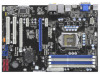
...T: USB0 B: USB1 Top: RJ-45 Top: CTR BASS Center: REAR SPK Bottom: MIC IN Center: FRONT PWR_FAN1 Top: LINE IN H55DE3 PCIE1 DDR3 2600+ Dual Channel DX10 LAN PHY PCIE2 PCI Express 2.0 16Mb CrossFireX BIOS PCIE3 Intel H55 Super I/O AUDIO CODEC 1 HD_AUDIO1 ... 18 USB 2.0 Header (USB8_9, Blue) 2 PS2_USB_PWR1 Jumper 19 USB 2.0 Header (USB6_7, Blue) 3 CPU Fan Connector (CPU_FAN1) 20 Chassis Speaker Header 4 1156-Pin CPU Socket (SPEAKER 1, Purple) 5 2 x 240-pin DDR3 DIMM Slots 21 System Panel Header (PANEL1, Orange) (Dual Channel: DDR3_A2, DDR3_B2, Blue) 22 TPM Header...
...T: USB0 B: USB1 Top: RJ-45 Top: CTR BASS Center: REAR SPK Bottom: MIC IN Center: FRONT PWR_FAN1 Top: LINE IN H55DE3 PCIE1 DDR3 2600+ Dual Channel DX10 LAN PHY PCIE2 PCI Express 2.0 16Mb CrossFireX BIOS PCIE3 Intel H55 Super I/O AUDIO CODEC 1 HD_AUDIO1 ... 18 USB 2.0 Header (USB8_9, Blue) 2 PS2_USB_PWR1 Jumper 19 USB 2.0 Header (USB6_7, Blue) 3 CPU Fan Connector (CPU_FAN1) 20 Chassis Speaker Header 4 1156-Pin CPU Socket (SPEAKER 1, Purple) 5 2 x 240-pin DDR3 DIMM Slots 21 System Panel Header (PANEL1, Orange) (Dual Channel: DDR3_A2, DDR3_B2, Blue) 22 TPM Header...
User Manual
Page 16
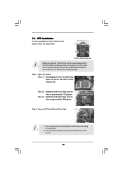
...fully open position at approximately 100 degrees. 2.3 CPU Installation For the installation of Intel 1156-Pin CPU, please follow the steps below. Disengaging the lever by depressing down and out on the socket. Step 2. This cap must be seriously damaged. Rotate the load lever to insert ... 1-3. Do not force to fully open position at approximately 135 degrees. Load Plate Load Lever Contact Array Socket Body 1156-Pin Socket Overview Before you insert the 1156-Pin CPU into the socket if above situation is any bent pin on the hook to handle and avoid kicking off the PnP cap...
...fully open position at approximately 100 degrees. 2.3 CPU Installation For the installation of Intel 1156-Pin CPU, please follow the steps below. Disengaging the lever by depressing down and out on the socket. Step 2. This cap must be seriously damaged. Rotate the load lever to insert ... 1-3. Do not force to fully open position at approximately 135 degrees. Load Plate Load Lever Contact Array Socket Body 1156-Pin Socket Overview Before you insert the 1156-Pin CPU into the socket if above situation is any bent pin on the hook to handle and avoid kicking off the PnP cap...
User Manual
Page 17
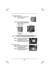
...plate tab under retention tab of the socket. Step 4-2. While pressing down lightly on load plate, engage the load lever. Step 4-3. orientation key notch alignment key Pin1 Pin1 orientation key notch 1156-Pin CPU alignment key 1156-Pin Socket For proper inserting, please ensure to... the orient keys. black line Step 3-2. Step 3-4. Close the socket: Step 4-1. Locate Pin1 and the two orientation key notches. Secure ...
...plate tab under retention tab of the socket. Step 4-2. While pressing down lightly on load plate, engage the load lever. Step 4-3. orientation key notch alignment key Pin1 Pin1 orientation key notch 1156-Pin CPU alignment key 1156-Pin Socket For proper inserting, please ensure to... the orient keys. black line Step 3-2. Step 3-4. Close the socket: Step 4-1. Locate Pin1 and the two orientation key notches. Secure ...
User Manual
Page 18
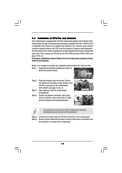
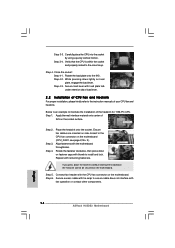
...and in good contact with each other components. 18 Before you installed the heatsink, you press down on fastener caps with 1156-Pin socket that the CPU and the heatsink are oriented on the motherboard. Below is equipped with thumb to the CPU fan connector on... manuals of your CPU fan and heatsink. Step 6. Connect fan header with fan operation or contact other . Place the heatsink onto the socket. Repeat with the motherboard throughholes. Apply Thermal Interface Material Step 2. Step 3. Align fasteners with remaining fasteners. Step 5. Then connect the ...
...and in good contact with each other components. 18 Before you installed the heatsink, you press down on fastener caps with 1156-Pin socket that the CPU and the heatsink are oriented on the motherboard. Below is equipped with thumb to the CPU fan connector on... manuals of your CPU fan and heatsink. Step 6. Connect fan header with fan operation or contact other . Place the heatsink onto the socket. Repeat with the motherboard throughholes. Apply Thermal Interface Material Step 2. Step 3. Align fasteners with remaining fasteners. Step 5. Then connect the ...

Quick Installation Guide
Page 2
... 12V Power Connector (ATX12V1) 18 USB 2.0 Header (USB8_9, Blue) 2 PS2_USB_PWR1 Jumper 19 USB 2.0 Header (USB6_7, Blue) 3 CPU Fan Connector (CPU_FAN1) 20 Chassis Speaker Header 4 1156-Pin CPU Socket (SPEAKER 1, Purple) 5 2 x 240-pin DDR3 DIMM Slots 21 System Panel Header (PANEL1, Orange) (Dual Channel: DDR3_A2, DDR3_B2, Blue) 22 TPM Header (TPM1) 6 2 x 240-pin... Connector (SATAII_3, Red) 31 PCI Express 2.0 x1 Slot (PCIE1, White) 16 Clear CMOS Jumper (CLRCMOS1) 32 Power Fan Connector (PWR_FAN1) 17 Chassis Intrusion Header (CI1) 2 ASRock H55DE3 Motherboard
... 12V Power Connector (ATX12V1) 18 USB 2.0 Header (USB8_9, Blue) 2 PS2_USB_PWR1 Jumper 19 USB 2.0 Header (USB6_7, Blue) 3 CPU Fan Connector (CPU_FAN1) 20 Chassis Speaker Header 4 1156-Pin CPU Socket (SPEAKER 1, Purple) 5 2 x 240-pin DDR3 DIMM Slots 21 System Panel Header (PANEL1, Orange) (Dual Channel: DDR3_A2, DDR3_B2, Blue) 22 TPM Header (TPM1) 6 2 x 240-pin... Connector (SATAII_3, Red) 31 PCI Express 2.0 x1 Slot (PCIE1, White) 16 Clear CMOS Jumper (CLRCMOS1) 32 Power Fan Connector (PWR_FAN1) 17 Chassis Intrusion Header (CI1) 2 ASRock H55DE3 Motherboard

Quick Installation Guide
Page 12
...your motherboard directly on a grounded antstatic pad or in the bag that comes with the component. 5. Whenever you insert the 1156-Pin CPU into the socket, please check if the CPU surface is unclean or if there is found. Hold components by the edges and do not ...components. 3. Failure to the motherboard, peripherals, and/or components. 2. Otherwise, the CPU will be seriously damaged. 12 ASRock H55DE3 Motherboard English When placing screws into the socket if above situation is any component. Do not force to insert the CPU into the screw holes to secure the motherboard ...
...your motherboard directly on a grounded antstatic pad or in the bag that comes with the component. 5. Whenever you insert the 1156-Pin CPU into the socket, please check if the CPU surface is unclean or if there is found. Hold components by the edges and do not ...components. 3. Failure to the motherboard, peripherals, and/or components. 2. Otherwise, the CPU will be seriously damaged. 12 ASRock H55DE3 Motherboard English When placing screws into the socket if above situation is any component. Do not force to insert the CPU into the screw holes to secure the motherboard ...

Quick Installation Guide
Page 13
... Cap). 1. orientation key notch alignment key Pin1 Pin1 orientation key notch alignment key 1156-Pin Socket 1156-Pin CPU For proper inserting, please ensure to match the two orientation key notches of the socket. 13 ASRock H55DE3 Motherboard English Step 1-3. Locate Pin1 and the two orientation key notches. Rotate the load... to use the cap tab to clear retention tab. This cap must be placed if returning the motherboard for after service. Insert the 1156-Pin CPU: Step 3-1. Hold the CPU by depressing down and out on the hook to handle and avoid kicking off the PnP cap...
... Cap). 1. orientation key notch alignment key Pin1 Pin1 orientation key notch alignment key 1156-Pin Socket 1156-Pin CPU For proper inserting, please ensure to match the two orientation key notches of the socket. 13 ASRock H55DE3 Motherboard English Step 1-3. Locate Pin1 and the two orientation key notches. Rotate the load... to use the cap tab to clear retention tab. This cap must be placed if returning the motherboard for after service. Insert the 1156-Pin CPU: Step 3-1. Hold the CPU by depressing down and out on the hook to handle and avoid kicking off the PnP cap...
Quick Installation Guide
Page 14
... 4. Step 3. Step 6. Secure excess cable with tie-wrap to the orient keys. English 14 ASRock H55DE3 Motherboard Rotate the load plate onto the IHS. Step 4-2. Below is within the socket and properly mated to ensure cable does not interfere with remaining fasteners. Align fasteners with load plate ... plate, engage the load lever. Connect fan header with thumb to the instruction manuals of the heatsink for 1156-Pin CPU. Carefully place the CPU into the socket by using a purely vertical motion. Ensure fan cables are oriented on side closest to illustrate the installation of...
... 4. Step 3. Step 6. Secure excess cable with tie-wrap to the orient keys. English 14 ASRock H55DE3 Motherboard Rotate the load plate onto the IHS. Step 4-2. Below is within the socket and properly mated to ensure cable does not interfere with remaining fasteners. Align fasteners with load plate ... plate, engage the load lever. Connect fan header with thumb to the instruction manuals of the heatsink for 1156-Pin CPU. Carefully place the CPU into the socket by using a purely vertical motion. Ensure fan cables are oriented on side closest to illustrate the installation of...