User Manual
Page 10
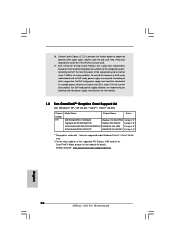
... off mode condition. 16. EuP, stands for Energy Using Product, was a provision regulated by European Union to adopt two different CPU cooler types, Socket LGA 775 and LGA 1156. Please be noticed that not all the 775 CPU Fan can be under 100 mA current consumption. For EuP ready power supply selection...
... off mode condition. 16. EuP, stands for Energy Using Product, was a provision regulated by European Union to adopt two different CPU cooler types, Socket LGA 775 and LGA 1156. Please be noticed that not all the 775 CPU Fan can be under 100 mA current consumption. For EuP ready power supply selection...
User Manual
Page 12
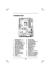
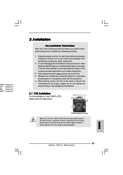
...: REAR SPK FRONT Bottom: CTR BASS MIC IN Top: LINE IN Center: Bottom: 38 LAN PHY 37 PWR_FAN1 CPU_FAN1 1394a CrossFireX CHA_FAN3 PCIE1 H55 Pro EuP Ready PCI Express 2.0 PCIE2 36 35 34 33 Super I/O PCIE3 PCIE4 AUDIO CODEC RoHS HD_AUDIO1 CD1 COM1 1 1 1 HDMI_SPDIF1 PCI1 PCI2...SATAII_1 SATAII_4_5 SATAII_2_3 7 8 9 10 11 12 13 14 15 16 17 18 19 20 21 22 23 1 PS2_USB_PWR1 Jumper 2 ATX 12V Power Connector (ATX12V1) 3 1156-Pin CPU Socket 4 2 x 240-pin DDR3 DIMM Slots (Dual Channel: DDR3_A2, DDR3_B2, Blue) 5 2 x 240-pin DDR3 DIMM Slots (Dual Channel: DDR3_A1, DDR3_B1, White)...
...: REAR SPK FRONT Bottom: CTR BASS MIC IN Top: LINE IN Center: Bottom: 38 LAN PHY 37 PWR_FAN1 CPU_FAN1 1394a CrossFireX CHA_FAN3 PCIE1 H55 Pro EuP Ready PCI Express 2.0 PCIE2 36 35 34 33 Super I/O PCIE3 PCIE4 AUDIO CODEC RoHS HD_AUDIO1 CD1 COM1 1 1 1 HDMI_SPDIF1 PCI1 PCI2...SATAII_1 SATAII_4_5 SATAII_2_3 7 8 9 10 11 12 13 14 15 16 17 18 19 20 21 22 23 1 PS2_USB_PWR1 Jumper 2 ATX 12V Power Connector (ATX12V1) 3 1156-Pin CPU Socket 4 2 x 240-pin DDR3 DIMM Slots (Dual Channel: DDR3_A2, DDR3_B2, Blue) 5 2 x 240-pin DDR3 DIMM Slots (Dual Channel: DDR3_A1, DDR3_B1, White)...
User Manual
Page 16
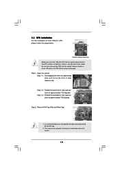
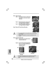
...the load plate to fully open position at approximately 135 degrees. Load Plate Load Lever Contact Array Socket Body 1156-Pin Socket Overview Before you insert the 1156-Pin CPU into the socket if above situation is found. Rotate the load lever to fully open position at approximately 100 degrees....retention tab. This cap must be seriously damaged. Step 1-2. 2.3 CPU Installation For the installation of Intel 1156-Pin CPU, please follow the steps below. Open the socket: Step 1-1. Otherwise, the CPU will be placed if returning the motherboard for after service. 16 Disengaging ...
...the load plate to fully open position at approximately 135 degrees. Load Plate Load Lever Contact Array Socket Body 1156-Pin Socket Overview Before you insert the 1156-Pin CPU into the socket if above situation is found. Rotate the load lever to fully open position at approximately 100 degrees....retention tab. This cap must be seriously damaged. Step 1-2. 2.3 CPU Installation For the installation of Intel 1156-Pin CPU, please follow the steps below. Open the socket: Step 1-1. Otherwise, the CPU will be placed if returning the motherboard for after service. 16 Disengaging ...

User Manual
Page 17
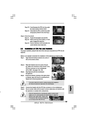
... properly mated to match the two orientation key notches of the CPU with black line. Close the socket: Step 4-1. Step 4-3. black line Step 3-2. Step 3-3. Step 3-4. Step 4. Step 4-2. Locate Pin1 and the two orientation key notches. Rotate the load plate onto the ... the CPU with load plate tab under retention tab of the socket. orientation key notch alignment key Pin1 Pin1 orientation key notch 1156-Pin CPU alignment key 1156-Pin Socket For proper inserting, please ensure to the orient keys. Step 3. Insert the 1156-Pin CPU: Step 3-1. Verify that the CPU is marked with...
... properly mated to match the two orientation key notches of the CPU with black line. Close the socket: Step 4-1. Step 4-3. black line Step 3-2. Step 3-3. Step 3-4. Step 4. Step 4-2. Locate Pin1 and the two orientation key notches. Rotate the load plate onto the ... the CPU with load plate tab under retention tab of the socket. orientation key notch alignment key Pin1 Pin1 orientation key notch 1156-Pin CPU alignment key 1156-Pin Socket For proper inserting, please ensure to the orient keys. Step 3. Insert the 1156-Pin CPU: Step 3-1. Verify that the CPU is marked with...

User Manual
Page 18
...clockwise, the heatsink cannot be noticed that the CPU and the heatsink are securely fastened and in good contact with 1156-Pin socket that supports Intel 1156-Pin CPU. Please be secured on the motherboard. Ensure that this motherboard supports Combo Cooler Option (C.C.O.), which provides the... flexible option to adopt two different CPU cooler types, Socket LGA 775 and LGA 1156. Apply thermal interface material onto center of IHS on fastener caps with the CPU fan connector on the motherboard (CPU_FAN1...
...clockwise, the heatsink cannot be noticed that the CPU and the heatsink are securely fastened and in good contact with 1156-Pin socket that supports Intel 1156-Pin CPU. Please be secured on the motherboard. Ensure that this motherboard supports Combo Cooler Option (C.C.O.), which provides the... flexible option to adopt two different CPU cooler types, Socket LGA 775 and LGA 1156. Apply thermal interface material onto center of IHS on fastener caps with the CPU fan connector on the motherboard (CPU_FAN1...

Quick Installation Guide
Page 2
Motherboard Layout English 1 PS2_USB_PWR1 Jumper 2 ATX 12V Power Connector (ATX12V1) 3 1156-Pin CPU Socket 4 2 x 240-pin DDR3 DIMM Slots (Dual Channel: DDR3_A2, DDR3_B2, Blue) 5 2 x 240-pin DDR3 DIMM Slots...(SATAII_1, Red) 10 SATAII Connector (SATAII_2_3, Red) 11 SATAII Connector (SATAII_4_5, Red) 12 Chassis Fan Connector (CHA_FAN3) 13 Intel H55 Chipset 14 Chassis Speaker Header (SPEAKER 1, Purple) 15 Primary IDE Connector (IDE1, Blue) 16 Chassis Intrusion Header (CI1) 17 Clear...x1 Slot (PCIE1, White) 39 CPU Fan Connector (CPU_FAN1) 40 Power Fan Connector (PWR_FAN1) 2 ASRock H55 Pro Motherboard
Motherboard Layout English 1 PS2_USB_PWR1 Jumper 2 ATX 12V Power Connector (ATX12V1) 3 1156-Pin CPU Socket 4 2 x 240-pin DDR3 DIMM Slots (Dual Channel: DDR3_A2, DDR3_B2, Blue) 5 2 x 240-pin DDR3 DIMM Slots...(SATAII_1, Red) 10 SATAII Connector (SATAII_2_3, Red) 11 SATAII Connector (SATAII_4_5, Red) 12 Chassis Fan Connector (CHA_FAN3) 13 Intel H55 Chipset 14 Chassis Speaker Header (SPEAKER 1, Purple) 15 Primary IDE Connector (IDE1, Blue) 16 Chassis Intrusion Header (CI1) 17 Clear...x1 Slot (PCIE1, White) 39 CPU Fan Connector (CPU_FAN1) 40 Power Fan Connector (PWR_FAN1) 2 ASRock H55 Pro Motherboard
Quick Installation Guide
Page 10
... the completed system. According to EuP, the total AC power of the completed system shall be used. 17. ASRock website: http://www.asrock.com/support/index.htm English 10 ASRock H55 Pro Motherboard According to Intel's suggestion, the EuP ready power supply must meet EuP standard, an EuP ready motherboard and... the power consumption for Energy Using Product, was a provision regulated by European Union to adopt two different CPU cooler types, Socket LGA 775 and LGA 1156. Please be noticed that not all the 775 CPU Fan can be under 100 mA current consumption. To meet the standard...
... the completed system. According to EuP, the total AC power of the completed system shall be used. 17. ASRock website: http://www.asrock.com/support/index.htm English 10 ASRock H55 Pro Motherboard According to Intel's suggestion, the EuP ready power supply must meet EuP standard, an EuP ready motherboard and... the power consumption for Energy Using Product, was a provision regulated by European Union to adopt two different CPU cooler types, Socket LGA 775 and LGA 1156. Please be noticed that not all the 775 CPU Fan can be under 100 mA current consumption. To meet the standard...
Quick Installation Guide
Page 11
...component. 5. English 11 ASRock H55 Pro Motherboard Whenever you insert the 1156-Pin CPU into the socket if above situation is any motherboard settings. 1. Installation Pre-installation Precautions Take note of Intel 1156-Pin CPU, please follow the steps below. 1156-Pin Socket Overview Before you uninstall any... component. Doing so may cause severe damage to insert the CPU into the socket, please check if the CPU surface is...
...component. 5. English 11 ASRock H55 Pro Motherboard Whenever you insert the 1156-Pin CPU into the socket if above situation is any motherboard settings. 1. Installation Pre-installation Precautions Take note of Intel 1156-Pin CPU, please follow the steps below. 1156-Pin Socket Overview Before you uninstall any... component. Doing so may cause severe damage to insert the CPU into the socket, please check if the CPU surface is...
Quick Installation Guide
Page 12
...: Step 3-1. Orient the CPU with black lines. Step 1. Step 3-2. orientation key notch alignment key Pin1 Pin1 orientation key notch alignment key 1156-Pin Socket 1156-Pin CPU For proper inserting, please ensure to handle and avoid kicking off the PnP cap. 2. Step 1-2. Rotate the load plate to fully...is recommended to use the cap tab to match the two orientation key notches of the CPU with the two alignment keys of the socket. 12 ASRock H55 Pro Motherboard Hold the CPU by depressing down and out on the hook to fully open position at approximately 135 degrees. Locate Pin1 and...
...: Step 3-1. Orient the CPU with black lines. Step 1. Step 3-2. orientation key notch alignment key Pin1 Pin1 orientation key notch alignment key 1156-Pin Socket 1156-Pin CPU For proper inserting, please ensure to handle and avoid kicking off the PnP cap. 2. Step 1-2. Rotate the load plate to fully...is recommended to use the cap tab to match the two orientation key notches of the CPU with the two alignment keys of the socket. 12 ASRock H55 Pro Motherboard Hold the CPU by depressing down and out on the hook to fully open position at approximately 135 degrees. Locate Pin1 and...
Quick Installation Guide
Page 13
... the instruction manuals of your CPU fan and heatsink. Step 4-2. Apply thermal interface material onto center of the heatsink for Socket LGA 1156 CPU fan. 13 ASRock H55 Pro Motherboard English Ensure fan cables are for 1156-Pin CPU. Connect fan header with remaining fasteners. Rotate the load plate onto the IHS. Secure load lever with...
... the instruction manuals of your CPU fan and heatsink. Step 4-2. Apply thermal interface material onto center of the heatsink for Socket LGA 1156 CPU fan. 13 ASRock H55 Pro Motherboard English Ensure fan cables are for 1156-Pin CPU. Connect fan header with remaining fasteners. Rotate the load plate onto the IHS. Secure load lever with...