
User Manual
Page 3
...1 1.2 Specifications 2 1.3 Motherboard Layout 6 1.4 I/O Panel 8 Chapter 2 Installation 10 2.1 Installing the CPU 11 2.2 Installing the CPU Fan and Heatsink 14 2.3 Installing Memory Modules (DIMM) 15 2.4 Expansion Slots (PCI Express Slots) 17 2.5 Jumpers Setup 18 2.6 Onboard Headers and Connectors 19 2.7 CrossFireXTM and Quad CrossFireXTM Operation Guide 23 2.7.1 Installing Two CrossFireXTM-Ready Graphics Cards 23 2.7.2 Driver Installation and Setup 25 Chapter 3 Software and Utilities Operation 26 3.1 Installing Drivers 26 3.2 A-Tuning 27 3.3 ASRock Live Update...
...1 1.2 Specifications 2 1.3 Motherboard Layout 6 1.4 I/O Panel 8 Chapter 2 Installation 10 2.1 Installing the CPU 11 2.2 Installing the CPU Fan and Heatsink 14 2.3 Installing Memory Modules (DIMM) 15 2.4 Expansion Slots (PCI Express Slots) 17 2.5 Jumpers Setup 18 2.6 Onboard Headers and Connectors 19 2.7 CrossFireXTM and Quad CrossFireXTM Operation Guide 23 2.7.1 Installing Two CrossFireXTM-Ready Graphics Cards 23 2.7.2 Driver Installation and Setup 25 Chapter 3 Software and Utilities Operation 26 3.1 Installing Drivers 26 3.2 A-Tuning 27 3.3 ASRock Live Update...

User Manual
Page 4
... 3.4 Creating Windows® 7 Installation Disk with USB 3.0 Drivers Packed 37 Chapter 4 UEFI SETUP UTILITY 41 4.1 Introduction 41 4.2 EZ Mode 42 4.3 Advanced Mode 43 4.3.1 UEFI Menu Bar 43 4.3.2 Navigation Keys 44 4.4 Main Screen 45 4.5 OC Tweaker Screen 46 4.6 Advanced Screen 54 4.6.1 CPU Configuration 55 4.6.2 Chipset Configuration 57 4.6.3 Storage Configuration 59 4.6.4 ACPI Configuration 60 4.6.5 USB Configuration 62 4.6.6 Trusted Computing 63 4.7 Tools 64 4.8 Hardware Health Event Monitoring Screen 67 4.9 Security Screen 69 4.10 Boot Screen 70...
... 3.4 Creating Windows® 7 Installation Disk with USB 3.0 Drivers Packed 37 Chapter 4 UEFI SETUP UTILITY 41 4.1 Introduction 41 4.2 EZ Mode 42 4.3 Advanced Mode 43 4.3.1 UEFI Menu Bar 43 4.3.2 Navigation Keys 44 4.4 Main Screen 45 4.5 OC Tweaker Screen 46 4.6 Advanced Screen 54 4.6.1 CPU Configuration 55 4.6.2 Chipset Configuration 57 4.6.3 Storage Configuration 59 4.6.4 ACPI Configuration 60 4.6.5 USB Configuration 62 4.6.6 Trusted Computing 63 4.7 Tools 64 4.8 Hardware Health Event Monitoring Screen 67 4.9 Security Screen 69 4.10 Boot Screen 70...
User Manual
Page 5
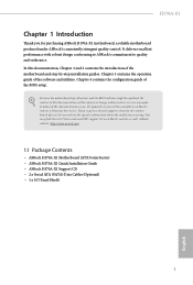
... Package Contents • ASRock H170A-X1 Motherboard (ATX Form Factor) • ASRock H170A-X1 Quick Installation Guide • ASRock H170A-X1 Support CD • 2 x Serial ATA (SATA) Data Cables (Optional) • 1 x I/O Panel Shield 1 English Chapter 3 contains the operation guide of the BIOS setup. You may find the latest VGA cards and CPU support list on ASRock's website without notice. Chapter 4 contains the configuration guide of the software and utilities. If you are using. Because the motherboard specifications and the BIOS software might be updated, the content of...
... Package Contents • ASRock H170A-X1 Motherboard (ATX Form Factor) • ASRock H170A-X1 Quick Installation Guide • ASRock H170A-X1 Support CD • 2 x Serial ATA (SATA) Data Cables (Optional) • 1 x I/O Panel Shield 1 English Chapter 3 contains the operation guide of the BIOS setup. You may find the latest VGA cards and CPU support list on ASRock's website without notice. Chapter 4 contains the configuration guide of the software and utilities. If you are using. Because the motherboard specifications and the BIOS software might be updated, the content of...

User Manual
Page 6
... DIMM Slots Expansion Slot • 2 x PCI Express 3.0 x16 Slots (PCIE2: x16 mode; capacity of system memory: 64GB • Supports Intel® Extreme Memory Profile (XMP) 2.0 • 15μ Gold Contact in non- PCIE4: x4 mode)* * Supports NVMe SSD as boot disks • 3 x PCI Express 3.0 x1 Slots (Flexible PCIe) • Supports AMD Quad CrossFireXTM and CrossFireXTM Graphics • Intel® HD Graphics Built-in Visuals and the VGA outputs can be supported only with processors which...
... DIMM Slots Expansion Slot • 2 x PCI Express 3.0 x16 Slots (PCIE2: x16 mode; capacity of system memory: 64GB • Supports Intel® Extreme Memory Profile (XMP) 2.0 • 15μ Gold Contact in non- PCIE4: x4 mode)* * Supports NVMe SSD as boot disks • 3 x PCI Express 3.0 x1 Slots (Flexible PCIe) • Supports AMD Quad CrossFireXTM and CrossFireXTM Graphics • Intel® HD Graphics Built-in Visuals and the VGA outputs can be supported only with processors which...
User Manual
Page 7
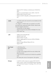
... Ethernet 802.3az • Supports PXE Rear Panel I/O • 1 x PS/2 Mouse Port • 1 x PS/2 Keyboard Port • 1 x DVI-D Port • 6 x USB 3.0 Ports (Supports ESD Protection (ASRock Full Spike Protection)) • 1 x RJ-45 LAN Port with max. H170A-X1 • Supports DVI-D with LED (ACT/LINK LED and SPEED LED) • HD Audio Jacks: Line in / Front Speaker / Microphone Storage • 6 x SATA3 6.0 Gb/s Connectors, support RAID (RAID 0, RAID 1, RAID 5, RAID 10, Intel Rapid Storage Technology 14 and Intel Smart Response Technology), NCQ, AHCI and Hot Plug English 3
... Ethernet 802.3az • Supports PXE Rear Panel I/O • 1 x PS/2 Mouse Port • 1 x PS/2 Keyboard Port • 1 x DVI-D Port • 6 x USB 3.0 Ports (Supports ESD Protection (ASRock Full Spike Protection)) • 1 x RJ-45 LAN Port with max. H170A-X1 • Supports DVI-D with LED (ACT/LINK LED and SPEED LED) • HD Audio Jacks: Line in / Front Speaker / Microphone Storage • 6 x SATA3 6.0 Gb/s Connectors, support RAID (RAID 0, RAID 1, RAID 5, RAID 10, Intel Rapid Storage Technology 14 and Intel Smart Response Technology), NCQ, AHCI and Hot Plug English 3

User Manual
Page 8
...1 x Power LED and Speaker Header • 1 x CPU Fan Connector (4-pin) • 2 x Chassis Fan Connectors (4-pin) • 1 x 24 pin ATX Power Connector • 1 x 8 pin 12V Power Connector • 1 x Front Panel Audio Connector • 2 x USB 2.0 Headers (Support 4 USB 2.0 ports) (Supports ESD Protection (ASRock Full Spike Protection)) • 1 x USB 3.0 Header (Supports 2 USB 3.0 ports) (Supports ESD Protection (ASRock Full Spike Protection)) BIOS Feature • AMI UEFI Legal BIOS with xHCI drivers packed into the ISO file is required) English 4 bit * To install Windows®...
...1 x Power LED and Speaker Header • 1 x CPU Fan Connector (4-pin) • 2 x Chassis Fan Connectors (4-pin) • 1 x 24 pin ATX Power Connector • 1 x 8 pin 12V Power Connector • 1 x Front Panel Audio Connector • 2 x USB 2.0 Headers (Support 4 USB 2.0 ports) (Supports ESD Protection (ASRock Full Spike Protection)) • 1 x USB 3.0 Header (Supports 2 USB 3.0 ports) (Supports ESD Protection (ASRock Full Spike Protection)) BIOS Feature • AMI UEFI Legal BIOS with xHCI drivers packed into the ISO file is required) English 4 bit * To install Windows®...

User Manual
Page 11
...) 4 2 x 288-pin DDR4 DIMM Slots (DDR4_A2, DDR4_B2) 5 ATX Power Connector (ATXPWR1) 6 USB 3.0 Header (USB3_4_5) 7 Chassis Fan Connector (CHA_FAN1) 8 Clear CMOS Jumper (CLRMOS1) 9 SATA3 Connector (SATA3_2) 10 Chassis Fan Connector (CHA_FAN2) 11 Power LED and Speaker Header (SPK_PLED1) 12 SATA3 Connector (SATA3_0) 13 System Panel Header (PANEL1) 14 SATA3 Connector (SATA3_1) 15 SATA3 Connector (SATA3_3) 16 SATA3 Connector (SATA3_5) 17 SATA3 Connector (SATA3_4) 18 USB 2.0 Header (USB2_3) 19 USB 2.0 Header (USB4_5) 20 TPM Header (TPMS1) 21 Front Panel Audio Header (HD_AUDIO1) H170A-X1 English 7
...) 4 2 x 288-pin DDR4 DIMM Slots (DDR4_A2, DDR4_B2) 5 ATX Power Connector (ATXPWR1) 6 USB 3.0 Header (USB3_4_5) 7 Chassis Fan Connector (CHA_FAN1) 8 Clear CMOS Jumper (CLRMOS1) 9 SATA3 Connector (SATA3_2) 10 Chassis Fan Connector (CHA_FAN2) 11 Power LED and Speaker Header (SPK_PLED1) 12 SATA3 Connector (SATA3_0) 13 System Panel Header (PANEL1) 14 SATA3 Connector (SATA3_1) 15 SATA3 Connector (SATA3_3) 16 SATA3 Connector (SATA3_5) 17 SATA3 Connector (SATA3_4) 18 USB 2.0 Header (USB2_3) 19 USB 2.0 Header (USB4_5) 20 TPM Header (TPMS1) 21 Front Panel Audio Header (HD_AUDIO1) H170A-X1 English 7

User Manual
Page 21
... that the power supply is switched off or the power cord is used for the card before you start the installation. PCIe slots: PCIE1 (PCIe 3.0 x1 slot) is used for PCI Express x1 lane width cards. PCIE4 (PCIe 3.0 x16 slot) is used for PCI Express x1 lane width cards. PCIE3 (PCIe 3.0 x1 slot) is used for PCI Express x16 lane width graphics cards. PCIe Slot Configurations Single Graphics Card Two Graphics Cards in CrossFireXTM Mode PCIE2 x16 x16 PCIE4 N/A x4 For a better thermal environment, please connect a chassis fan to the motherboard's chassis fan connector (CHA_FAN1 or...
... that the power supply is switched off or the power cord is used for the card before you start the installation. PCIe slots: PCIE1 (PCIe 3.0 x1 slot) is used for PCI Express x1 lane width cards. PCIE4 (PCIe 3.0 x16 slot) is used for PCI Express x1 lane width cards. PCIE3 (PCIe 3.0 x1 slot) is used for PCI Express x16 lane width graphics cards. PCIe Slot Configurations Single Graphics Card Two Graphics Cards in CrossFireXTM Mode PCIE2 x16 x16 PCIE4 N/A x4 For a better thermal environment, please connect a chassis fan to the motherboard's chassis fan connector (CHA_FAN1 or...

User Manual
Page 22
... jumpers are "Short" when a jumper cap is removed. If no jumper cap is placed on the pins, the jumper is "Open". After waiting for 5 seconds. If you update the BIOS. The illustration shows a 3-pin jumper whose pin1 and pin2 are setup. Please be noted that the password, date, time, and user default profile will be cleared only if the CMOS battery is placed on CLRMOS1 for 15 seconds, use a jumper...
... jumpers are "Short" when a jumper cap is removed. If no jumper cap is placed on the pins, the jumper is "Open". After waiting for 5 seconds. If you update the BIOS. The illustration shows a 3-pin jumper whose pin1 and pin2 are setup. Please be noted that the password, date, time, and user default profile will be cleared only if the CMOS battery is placed on CLRMOS1 for 15 seconds, use a jumper...

User Manual
Page 23
... this header according to this header, make sure the wire assignments and the pin assignments are NOT jumpers. When connecting your system using the power switch. HDLED (Hard Drive Activity LED): Connect to the reset switch on when the hard drive is operating. The LED is on the chassis front panel. You may differ by chassis. RESET (Reset Switch): Connect to the hard drive activity LED on when the system is reading or writing data. H170A-X1 2.6 Onboard Headers and Connectors Onboard headers and connectors are...
... this header according to this header, make sure the wire assignments and the pin assignments are NOT jumpers. When connecting your system using the power switch. HDLED (Hard Drive Activity LED): Connect to the reset switch on when the hard drive is operating. The LED is on the chassis front panel. You may differ by chassis. RESET (Reset Switch): Connect to the hard drive activity LED on when the system is reading or writing data. H170A-X1 2.6 Onboard Headers and Connectors Onboard headers and connectors are...

User Manual
Page 25
... HD audio panel only. E. If you use a 20-pin ATX power supply, please plug it to Pin 1-3. Connect Audio_R (RIN) to OUT2_R and Audio_L (LIN) to the front panel audio header by the steps below: A. H170A-X1 Front Panel Audio Header (9-pin HD_AUDIO1) (see p.6, No. 10) GND FAN_VOLTAGE CHA_FAN_SPEED FAN_SPEED_CONTROL Please connect fan cables to the fan connectors and match the black wire to the ground pin. If you plan to connect a 3-Pin CPU fan, please connect it along Pin 1 and Pin 13...
... HD audio panel only. E. If you use a 20-pin ATX power supply, please plug it to Pin 1-3. Connect Audio_R (RIN) to OUT2_R and Audio_L (LIN) to the front panel audio header by the steps below: A. H170A-X1 Front Panel Audio Header (9-pin HD_AUDIO1) (see p.6, No. 10) GND FAN_VOLTAGE CHA_FAN_SPEED FAN_SPEED_CONTROL Please connect fan cables to the fan connectors and match the black wire to the ground pin. If you plan to connect a 3-Pin CPU fan, please connect it along Pin 1 and Pin 13...

User Manual
Page 27
... graphics card vendor for details.) English 23 Different CrossFireXTM cards may require different methods to three identical PCI Express x16 graphics cards. 1. If you pair a 12-pipe CrossFireXTM Edition card with this motherboard. Please refer to the AMD's website for detailed installation guide. 2.7.1 Installing Two CrossFireXTM-Ready Graphics Cards Step 1 Insert one graphics card into PCIE2 slot and the other graphics card to your graphics card driver supports AMD CrossFireXTM technology. CrossFire Bridge Step 2 Connect two graphics cards by installing...
... graphics card vendor for details.) English 23 Different CrossFireXTM cards may require different methods to three identical PCI Express x16 graphics cards. 1. If you pair a 12-pipe CrossFireXTM Edition card with this motherboard. Please refer to the AMD's website for detailed installation guide. 2.7.1 Installing Two CrossFireXTM-Ready Graphics Cards Step 1 Insert one graphics card into PCIE2 slot and the other graphics card to your graphics card driver supports AMD CrossFireXTM technology. CrossFire Bridge Step 2 Connect two graphics cards by installing...

User Manual
Page 30
... a specific item then follow the order from top to bottom to your system will be auto-detected and listed on the file "ASRSETUP.EXE" in your CD-ROM drive. "KB2720599": http://support.microsoft.com/kb/2720599/en-us 26 English The CD automatically displays the Main Menu if "AUTORUN" is enabled in the Support CD to install it. Chapter 3 Software and Utilities Operation 3.1 Installing Drivers The Support CD...
... a specific item then follow the order from top to bottom to your system will be auto-detected and listed on the file "ASRSETUP.EXE" in your CD-ROM drive. "KB2720599": http://support.microsoft.com/kb/2720599/en-us 26 English The CD automatically displays the Main Menu if "AUTORUN" is enabled in the Support CD to install it. Chapter 3 Software and Utilities Operation 3.1 Installing Drivers The Support CD...
User Manual
Page 41
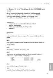
.... 37 English Step 4 Copy "boot.wim" and "install.wim" files from the "Sources" folder in the ASRock Support CD) • Windows® PC Instructions Step 1 Create a new folder under the "asrock" folder. Due to function properly. Name the subfolder "mount" and "usb3" as an example. H170A-X1 3.4 Creating Windows® 7 Installation Disk with the Intel® USB 3.0 eXtensible Host Controller (xHCI) drivers packed into the ISO...
.... 37 English Step 4 Copy "boot.wim" and "install.wim" files from the "Sources" folder in the ASRock Support CD) • Windows® PC Instructions Step 1 Create a new folder under the "asrock" folder. Due to function properly. Name the subfolder "mount" and "usb3" as an example. H170A-X1 3.4 Creating Windows® 7 Installation Disk with the Intel® USB 3.0 eXtensible Host Controller (xHCI) drivers packed into the ISO...

User Manual
Page 62
... Power and Keyboard LEDs when the system enters into Standby/Hibernation mode. 58 English It will start to keep the integrated graphics enabled at all PCH DMI devices. Front Panel Enable/disable front panel HD audio. Restore on CPU side of the DMI Link. If [Power On] is on. Onboard HD Audio Enable/disable onboard HD audio. DMI ASPM Support This option enables/disables the control of ASPM on AC/Power Loss Select the power state after a power failure. Deep Sleep Configure deep sleep mode...
... Power and Keyboard LEDs when the system enters into Standby/Hibernation mode. 58 English It will start to keep the integrated graphics enabled at all PCH DMI devices. Front Panel Enable/disable front panel HD audio. Restore on CPU side of the DMI Link. If [Power On] is on. Onboard HD Audio Enable/disable onboard HD audio. DMI ASPM Support This option enables/disables the control of ASPM on AC/Power Loss Select the power state after a power failure. Deep Sleep Configure deep sleep mode...

User Manual
Page 63
4.6.3 Storage Configuration H170A-X1 SATA Controller(s) Enable/disable the SATA controllers. AHCI (Advanced Host Controller Interface) supports NCQ and other new features that improve performance. Hard Disk S.M.A.R.T. SATA Mode Selection AHCI: Supports new features that will improve SATA disk performance but IDE mode does not have these advantages. SATA Aggressive Link Power Management SATA Aggressive Link Power Management allows SATA devices to save power. It is only supported by AHCI mode. S.M.A.R.T stands for computer hard disk drives to detect and report on various ...
4.6.3 Storage Configuration H170A-X1 SATA Controller(s) Enable/disable the SATA controllers. AHCI (Advanced Host Controller Interface) supports NCQ and other new features that improve performance. Hard Disk S.M.A.R.T. SATA Mode Selection AHCI: Supports new features that will improve SATA disk performance but IDE mode does not have these advantages. SATA Aggressive Link Power Management SATA Aggressive Link Power Management allows SATA devices to save power. It is only supported by AHCI mode. S.M.A.R.T stands for computer hard disk drives to detect and report on various ...

User Manual
Page 68
... internet access at specified times via OMG. Please setup network configuration before using UEFI Tech Service. UEFI Tech Service Contact ASRock Tech Service if you are having trouble with your USB storage device. You may schedule the starting and ending hours of your current PC and the devices connected. In order to prevent users from the support CD to your PC. Easy RAID Installer Easy RAID Installer helps you can start installing the operating system in RAID mode...
... internet access at specified times via OMG. Please setup network configuration before using UEFI Tech Service. UEFI Tech Service Contact ASRock Tech Service if you are having trouble with your USB storage device. You may schedule the starting and ending hours of your current PC and the devices connected. In order to prevent users from the support CD to your PC. Easy RAID Installer Easy RAID Installer helps you can start installing the operating system in RAID mode...
User Manual
Page 69
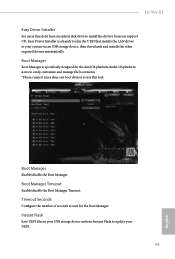
... boot menu. *Please connect more than one boot devices to use this tool. Boot Manager Enable/disable the Boot Manager. Boot Manager Timeout Enable/disable the Boot Manager Timeout. Boot Manager Boot Manager is a handy tool in your USB storage device and run Instant Flash to update your system via an USB storage device, then downloads and installs the other required drivers automatically. H170A-X1 Easy Driver Installer For users that don't have an optical disk drive to install the drivers from our support CD, Easy Driver Installer is specifically...
... boot menu. *Please connect more than one boot devices to use this tool. Boot Manager Enable/disable the Boot Manager. Boot Manager Timeout Enable/disable the Boot Manager Timeout. Boot Manager Boot Manager is a handy tool in your USB storage device and run Instant Flash to update your system via an USB storage device, then downloads and installs the other required drivers automatically. H170A-X1 Easy Driver Installer For users that don't have an optical disk drive to install the drivers from our support CD, Easy Driver Installer is specifically...
User Manual
Page 70
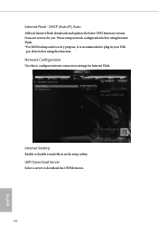
Please setup network configuration before using Internet Flash. *For BIOS backup and recovery purpose, it is recommended to plug in the setup utility. Network Configuration Use this function. Internet Setting Enable or disable sound effects in your USB pen drive before using this to download the UEFI firmware. 66 English UEFI Download Server Select a server to configure internet connection settings for you. DHCP (Auto IP), Auto ASRock Internet Flash downloads and updates the latest UEFI firmware version from our servers for Internet Flash. Internet Flash -
Please setup network configuration before using Internet Flash. *For BIOS backup and recovery purpose, it is recommended to plug in the setup utility. Network Configuration Use this function. Internet Setting Enable or disable sound effects in your USB pen drive before using this to download the UEFI firmware. 66 English UEFI Download Server Select a server to configure internet connection settings for you. DHCP (Auto IP), Auto ASRock Internet Flash downloads and updates the latest UEFI firmware version from our servers for Internet Flash. Internet Flash -
User Manual
Page 73
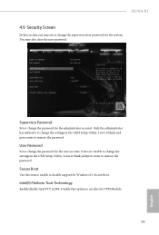
... remove the password. H170A-X1 4.9 Security Screen In this option to use discrete TPM Module. 69 English Leave it blank and press enter to change the settings in the UEFI Setup Utility. Disable this section you may also clear the user password. Users are unable to remove the password. Secure Boot Use this item to change the password for the administrator account. Only the administrator has authority to enable or disable support for the system. User Password Set or change the settings...
... remove the password. H170A-X1 4.9 Security Screen In this option to use discrete TPM Module. 69 English Leave it blank and press enter to change the settings in the UEFI Setup Utility. Disable this section you may also clear the user password. Users are unable to remove the password. Secure Boot Use this item to change the password for the administrator account. Only the administrator has authority to enable or disable support for the system. User Password Set or change the settings...


