
User Manual
Page 4
... (PCI Express Slots) 17 2.5 Jumpers Setup 18 2.6 Onboard Headers and Connectors 19 Chapter 3 Software and Utilities Operation 23 3.1 Installing Drivers 23 3.2 ASRock Live Update & APP Shop 24 3.2.1 UI Overview 24 3.2.2 Apps 25 3.2.3 BIOS & Drivers 28 3.2.4 Setting 29 3.3 Enabling USB Ports for Windows® 7 Installation 30 Chapter 4 UEFI SETUP UTILITY 33 4.1 Introduction 33
... (PCI Express Slots) 17 2.5 Jumpers Setup 18 2.6 Onboard Headers and Connectors 19 Chapter 3 Software and Utilities Operation 23 3.1 Installing Drivers 23 3.2 ASRock Live Update & APP Shop 24 3.2.1 UI Overview 24 3.2.2 Apps 25 3.2.3 BIOS & Drivers 28 3.2.4 Setting 29 3.3 Enabling USB Ports for Windows® 7 Installation 30 Chapter 4 UEFI SETUP UTILITY 33 4.1 Introduction 33
User Manual
Page 6
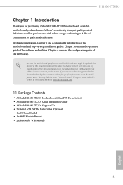
...; ASRock H110M-ITX/D3 Motherboard (Mini-ITX Form Factor) • ASRock H110M-ITX/D3 Quick Installation Guide • ASRock H110M-ITX/D3 Support CD • 2 x Serial ATA (SATA) Data Cables (Optional) • 1 x I/O Panel Shield • 1 x WiFi Module Bracket • 2 x Screws for purchasing ASRock H110M-ITX/D3 motherboard, a reliable motherboard produced under ASRock's consistently stringent quality control. Chapter 3 contains the operation guide of the BIOS setup...
...; ASRock H110M-ITX/D3 Motherboard (Mini-ITX Form Factor) • ASRock H110M-ITX/D3 Quick Installation Guide • ASRock H110M-ITX/D3 Support CD • 2 x Serial ATA (SATA) Data Cables (Optional) • 1 x I/O Panel Shield • 1 x WiFi Module Bracket • 2 x Screws for purchasing ASRock H110M-ITX/D3 motherboard, a reliable motherboard produced under ASRock's consistently stringent quality control. Chapter 3 contains the operation guide of the BIOS setup...
User Manual
Page 9
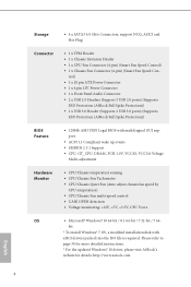
... • 1 x 4 pin 12V Power Connector • 1 x Front Panel Audio Connector • 2 x USB 2.0 Headers (Support 3 USB 2.0 ports) (Supports ESD Protection (ASRock Full Spike Protection)) • 1 x USB 3.0 Header (Supports 2 USB 3.0 ports) (Supports ESD Protection (ASRock Full Spike Protection)) BIOS Feature • 128Mb AMI UEFI Legal BIOS with xHCI drivers packed into the ISO file is required.
... • 1 x 4 pin 12V Power Connector • 1 x Front Panel Audio Connector • 2 x USB 2.0 Headers (Support 3 USB 2.0 ports) (Supports ESD Protection (ASRock Full Spike Protection)) • 1 x USB 3.0 Header (Supports 2 USB 3.0 ports) (Supports ESD Protection (ASRock Full Spike Protection)) BIOS Feature • 128Mb AMI UEFI Legal BIOS with xHCI drivers packed into the ISO file is required.
User Manual
Page 10
H110M-ITX/D3 Certifications • FCC, CE, WHQL • ErP/EuP Ready (ErP/EuP ready power supply is required) * For detailed product information, please visit our website: http://www.asrock.com Please realize that there is a certain risk involved with overclocking, including adjusting the setting in the BIOS, applying Untied Overclocking Technology, or using third...
H110M-ITX/D3 Certifications • FCC, CE, WHQL • ErP/EuP Ready (ErP/EuP ready power supply is required) * For detailed product information, please visit our website: http://www.asrock.com Please realize that there is a certain risk involved with overclocking, including adjusting the setting in the BIOS, applying Untied Overclocking Technology, or using third...
User Manual
Page 11
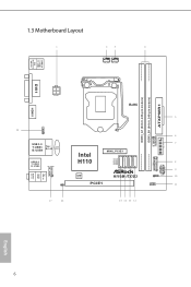
1.3 Motherboard Layout CHA_FAN1 CPU_FAN1 USB 2.0 T: USB1 B: USB2 PS2 Keyboard /Mouse DVI1 HDMI1 AT X P W R 1 DDR3_A1 (64 bit, 240-pin module) DDR3_B1 (64 bit, 240-pin module) ATX12V1 RoHS USB11 1 USB 3.0 T: USB3 B: USB4 Top: RJ-45 CMOS Battery USB 2.0 T: USB5 B: USB6 HD_AUDIO1 1 CI1 1 Intel H110 SATA3_3 SATA3_2 SATA3_1 SATA3_0 MINI_PCIE1 128Mb BIOS PCIE1 H110M-ITX/D3 1 USB_9_10 1 SPEAKER1 1 1 PANEL1 CLRMOS1 1 Top: LINE IN Center: FRONT Bottom: MIC IN USB3_7_8 TPMS1 PLED PWRBTN HDLED RESET English 6
1.3 Motherboard Layout CHA_FAN1 CPU_FAN1 USB 2.0 T: USB1 B: USB2 PS2 Keyboard /Mouse DVI1 HDMI1 AT X P W R 1 DDR3_A1 (64 bit, 240-pin module) DDR3_B1 (64 bit, 240-pin module) ATX12V1 RoHS USB11 1 USB 3.0 T: USB3 B: USB4 Top: RJ-45 CMOS Battery USB 2.0 T: USB5 B: USB6 HD_AUDIO1 1 CI1 1 Intel H110 SATA3_3 SATA3_2 SATA3_1 SATA3_0 MINI_PCIE1 128Mb BIOS PCIE1 H110M-ITX/D3 1 USB_9_10 1 SPEAKER1 1 1 PANEL1 CLRMOS1 1 Top: LINE IN Center: FRONT Bottom: MIC IN USB3_7_8 TPMS1 PLED PWRBTN HDLED RESET English 6
User Manual
Page 23
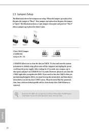
... be detected. The illustration shows a 3-pin jumper whose pin1 and pin2 are setup. However, please do the clear-CMOS action. English 18 Please adjust the BIOS option "Clear Status" to default setup, please turn off the computer and unplug the power cord from the power supply. To clear and reset the... system parameters to clear the record of previous chassis intrusion status. If you to clear the CMOS when you just finish updating the BIOS, you must boot up the system first, and then shut it down before you do not clear the CMOS right after you update the...
... be detected. The illustration shows a 3-pin jumper whose pin1 and pin2 are setup. However, please do the clear-CMOS action. English 18 Please adjust the BIOS option "Clear Status" to default setup, please turn off the computer and unplug the power cord from the power supply. To clear and reset the... system parameters to clear the record of previous chassis intrusion status. If you to clear the CMOS when you just finish updating the BIOS, you must boot up the system first, and then shut it down before you do not clear the CMOS right after you update the...
User Manual
Page 33
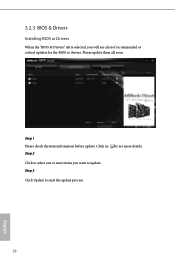
3.2.3 BIOS & Drivers Installing BIOS or Drivers When the "BIOS & Drivers" tab is selected, you want to update. Click to select one or more items you will see more details. Step 1 Please check the item information before update. Step 3 Click Update to see a list of recommended or critical updates for the BIOS or drivers. Click on Step 2 to start the update process. 28 English Please update them all soon.
3.2.3 BIOS & Drivers Installing BIOS or Drivers When the "BIOS & Drivers" tab is selected, you want to update. Click to select one or more items you will see more details. Step 1 Please check the item information before update. Step 3 Click Update to see a list of recommended or critical updates for the BIOS or drivers. Click on Step 2 to start the update process. 28 English Please update them all soon.
User Manual
Page 40
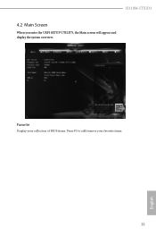
Favorite Display your collection of BIOS items. Press F5 to add/remove your favorite items. 35 English H110M-ITX/D3 4.2 Main Screen When you enter the UEFI SETUP UTILITY, the Main screen will appear and display the system overview.
Favorite Display your collection of BIOS items. Press F5 to add/remove your favorite items. 35 English H110M-ITX/D3 4.2 Main Screen When you enter the UEFI SETUP UTILITY, the Main screen will appear and display the system overview.
User Manual
Page 62
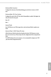
...255 Min: 1 Instant Flash Save UEFI files in your UEFI. DHCP (Auto IP), Auto ASRock Internet Flash downloads and updates the latest UEFI firmware version from our servers for you. H110M-ITX/D3 Dehumidifier Duration Configure the duration of the CPU fan while Dehumidifier is recommended to plug in... your USB storage device and run Instant Flash to update your USB pen drive before using Internet Flash. *For BIOS backup and recovery purpose, ...
...255 Min: 1 Instant Flash Save UEFI files in your UEFI. DHCP (Auto IP), Auto ASRock Internet Flash downloads and updates the latest UEFI firmware version from our servers for you. H110M-ITX/D3 Dehumidifier Duration Configure the duration of the CPU fan while Dehumidifier is recommended to plug in... your USB storage device and run Instant Flash to update your USB pen drive before using Internet Flash. *For BIOS backup and recovery purpose, ...


