
User Manual
Page 2
...may not be liable for any errors or omissions that may apply, see www.dtsc.ca.gov/hazardouswaste/ perchlorate" ASRock Website: http://www.asrock.com When you discard the Lithium battery in California, USA, please follow the related regulations in the documentation or product...and corporate names appearing in this documentation, ASRock does not provide warranty of any kind, either expressed or implied, including but not limited to the following two conditions: (1) this device may not cause harmful interference, and (2) this motherboard contains Perchlorate, a toxic substance controlled ...
...may not be liable for any errors or omissions that may apply, see www.dtsc.ca.gov/hazardouswaste/ perchlorate" ASRock Website: http://www.asrock.com When you discard the Lithium battery in California, USA, please follow the related regulations in the documentation or product...and corporate names appearing in this documentation, ASRock does not provide warranty of any kind, either expressed or implied, including but not limited to the following two conditions: (1) this device may not cause harmful interference, and (2) this motherboard contains Perchlorate, a toxic substance controlled ...
User Manual
Page 4
... 1 Introduction 1 1.1 Package Contents 1 1.2 Specifications 2 1.3 Motherboard Layout 6 1.4 I/O Panel 8 Chapter 2 Installation 10 2.1 Installing the CPU 11 2.2 Installing the CPU Fan and Heatsink 14 2.3 Installing Memory Modules (DIMM) 15 2.4 Expansion Slots (PCI Express Slots) 17 2.5 Onboard Headers and Connectors 18 Chapter 3 Software and Utilities Operation 22 3.1 Installing Drivers 22 3.2 ASRock Live Update & APP Shop 23...
... 1 Introduction 1 1.1 Package Contents 1 1.2 Specifications 2 1.3 Motherboard Layout 6 1.4 I/O Panel 8 Chapter 2 Installation 10 2.1 Installing the CPU 11 2.2 Installing the CPU Fan and Heatsink 14 2.3 Installing Memory Modules (DIMM) 15 2.4 Expansion Slots (PCI Express Slots) 17 2.5 Onboard Headers and Connectors 18 Chapter 3 Software and Utilities Operation 22 3.1 Installing Drivers 22 3.2 ASRock Live Update & APP Shop 23...
User Manual
Page 6
... of this documentation occur, the updated version will be available on ASRock's website as well. Chapter 4 contains the configuration guide of the software and utilities. ASRock website http://www.asrock.com. 1.1 Package Contents • ASRock H110M-HDS Motherboard (Micro ATX Form Factor) • ASRock H110M-HDS Quick Installation Guide • ASRock H110M-HDS Support CD • 2 x Serial ATA (SATA) Data Cables (Optional) •...
... of this documentation occur, the updated version will be available on ASRock's website as well. Chapter 4 contains the configuration guide of the software and utilities. ASRock website http://www.asrock.com. 1.1 Package Contents • ASRock H110M-HDS Motherboard (Micro ATX Form Factor) • ASRock H110M-HDS Quick Installation Guide • ASRock H110M-HDS Support CD • 2 x Serial ATA (SATA) Data Cables (Optional) •...
User Manual
Page 11
1.3 Motherboard Layout 1 2 PS 2 Mouse PS2 Keyboard ATX12V1 CPU_FAN1 3 4 CHA_FAN1 DVI1 DDR4_A1 (64 bit, 288-pin module) DDR4_B1 (64 bit,288-pin module) ATXPWR1 HDMI1 5 USB 3.0 T: USB1 B: USB2 USB 2.0 T: USB0 B: USB1 Top: RJ-45 USB 2.0 T: USB2 B: USB3 RoHS Intel CMOS Battery SATA3_3 SATA3_2 SATA3_1 SATA3_0 USB3_3_4 1 Top: LINE IN Center: FRONT Bottom: MIC IN 6 1 H110 HD_AUDIO1 16 7 PLED PWRBTN HDLED RESET PCIE1 PANEL1 SPK_CI1 1 USB_4_5 1 1 8 BIOS ROM H110M-HDS Audio CODEC PCIE2 TPMS1 9 CLRMOS1 15 14 13 12 11 10 English 6
1.3 Motherboard Layout 1 2 PS 2 Mouse PS2 Keyboard ATX12V1 CPU_FAN1 3 4 CHA_FAN1 DVI1 DDR4_A1 (64 bit, 288-pin module) DDR4_B1 (64 bit,288-pin module) ATXPWR1 HDMI1 5 USB 3.0 T: USB1 B: USB2 USB 2.0 T: USB0 B: USB1 Top: RJ-45 USB 2.0 T: USB2 B: USB3 RoHS Intel CMOS Battery SATA3_3 SATA3_2 SATA3_1 SATA3_0 USB3_3_4 1 Top: LINE IN Center: FRONT Bottom: MIC IN 6 1 H110 HD_AUDIO1 16 7 PLED PWRBTN HDLED RESET PCIE1 PANEL1 SPK_CI1 1 USB_4_5 1 1 8 BIOS ROM H110M-HDS Audio CODEC PCIE2 TPMS1 9 CLRMOS1 15 14 13 12 11 10 English 6
User Manual
Page 15
... do not touch the ICs. • Whenever you install motherboard components or change any components, place them on a carpet. Chapter 2 Installation This is a Micro ATX form factor motherboard. Before you install the motherboard, study the configuration of the following precautions before you handle ...components by the edges and do so may damage the motherboard. 10 English Doing so may cause physical injuries and damages to motherboard components. • In order to avoid damage from static electricity to the motherboard's components, NEVER place your chassis to ensure that comes...
... do not touch the ICs. • Whenever you install motherboard components or change any components, place them on a carpet. Chapter 2 Installation This is a Micro ATX form factor motherboard. Before you install the motherboard, study the configuration of the following precautions before you handle ...components by the edges and do so may damage the motherboard. 10 English Doing so may cause physical injuries and damages to motherboard components. • In order to avoid damage from static electricity to the motherboard's components, NEVER place your chassis to ensure that comes...
User Manual
Page 18
The cover must be placed if you wish to return the motherboard for after service. 13 English H110M-HDS Please save and replace the cover if the processor is removed.
The cover must be placed if you wish to return the motherboard for after service. 13 English H110M-HDS Please save and replace the cover if the processor is removed.
User Manual
Page 20
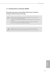
For dual channel configuration, you force the DIMM into a DDR4 slot; It will cause permanent damage to the motherboard and the DIMM if you always need to install identical (the same brand, speed, size and chip-type) DDR4 DIMM pairs. 2. It is...not allowed to activate Dual Channel Memory Technology with only one correct orientation. otherwise, this motherboard and DIMM may be damaged.. The DIMM only fits in one memory module installed. 3. H110M-HDS 2.3 Installing Memory Modules (DIMM) This motherboard provides two 288-pin DDR4 (Double Data Rate 4) DIMM slots, and supports Dual Channel...
For dual channel configuration, you force the DIMM into a DDR4 slot; It will cause permanent damage to the motherboard and the DIMM if you always need to install identical (the same brand, speed, size and chip-type) DDR4 DIMM pairs. 2. It is...not allowed to activate Dual Channel Memory Technology with only one correct orientation. otherwise, this motherboard and DIMM may be damaged.. The DIMM only fits in one memory module installed. 3. H110M-HDS 2.3 Installing Memory Modules (DIMM) This motherboard provides two 288-pin DDR4 (Double Data Rate 4) DIMM slots, and supports Dual Channel...
User Manual
Page 22
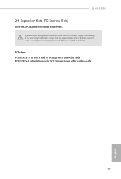
H110M-HDS 2.4 Expansion Slots (PCI Express Slots) There are 2 PCI Express slots on the motherboard. Before installing an expansion card, please make necessary hardware settings for PCI Express x16 lane width graphics cards. 17 English Please read the documentation of the expansion card and make sure that the power supply is switched off or the power cord is used for the card before you start the installation. PCIe slots: PCIE1 (PCIe 2.0 x1 slot) is used for PCI Express x1 lane width cards PCIE2 (PCIe 3.0 x16 slot) is unplugged.
H110M-HDS 2.4 Expansion Slots (PCI Express Slots) There are 2 PCI Express slots on the motherboard. Before installing an expansion card, please make necessary hardware settings for PCI Express x16 lane width graphics cards. 17 English Please read the documentation of the expansion card and make sure that the power supply is switched off or the power cord is used for the card before you start the installation. PCIe slots: PCIE1 (PCIe 2.0 x1 slot) is used for PCI Express x1 lane width cards PCIE2 (PCIe 3.0 x16 slot) is unplugged.
User Manual
Page 23
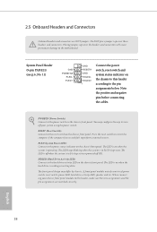
... LED is off when the system is in S4 sleep state or powered off your chassis front panel module to this header according to the motherboard. When connecting your system using the power switch. Do NOT place jumper caps over the headers and connectors will cause permanent damage to the pin...
... LED is off when the system is in S4 sleep state or powered off your chassis front panel module to this header according to the motherboard. When connecting your system using the power switch. Do NOT place jumper caps over the headers and connectors will cause permanent damage to the pin...
User Manual
Page 24
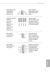
H110M-HDS Chassis Intrusion and Speaker Header (7-pin SPK_CI1) (see p.6, No. 12) 1 SIGNAL GND DUMMY Please connect the +5V chassis intrusion and the DUMMY chassis speaker to 6.0 ...+ GND USB_PWR PP+ GND DUMMY Besides four USB 2.0 ports on the I /O panel, there IntA_PB_SSRX+ GND is one header on this motherboard. Each USB 2.0 header can support two ports. 1 English 19 IntA_PB_SSTX+ motherboard. USB 3.0 Header (19-pin USB3_3_4) (see p.6, No. 9) SATA3_3 SATA3_2 SATA3_1 SATA3_0 These four SATA3 connectors support SATA data cables for...
H110M-HDS Chassis Intrusion and Speaker Header (7-pin SPK_CI1) (see p.6, No. 12) 1 SIGNAL GND DUMMY Please connect the +5V chassis intrusion and the DUMMY chassis speaker to 6.0 ...+ GND USB_PWR PP+ GND DUMMY Besides four USB 2.0 ports on the I /O panel, there IntA_PB_SSRX+ GND is one header on this motherboard. Each USB 2.0 header can support two ports. 1 English 19 IntA_PB_SSTX+ motherboard. USB 3.0 Header (19-pin USB3_3_4) (see p.6, No. 9) SATA3_3 SATA3_2 SATA3_1 SATA3_0 These four SATA3 connectors support SATA data cables for...
User Manual
Page 25
... instructions in the Realtek Control panel and adjust "Recording Volume". English 20 Front Panel Audio Header (9-pin HD_AUDIO1) (see p.6, No. 2) This motherboard pro- Connect Audio_R (RIN) to OUT2_R and Audio_L (LIN) to install your system. 2. You don't need to function correctly. C. FAN_VOLTAGE ... manual to OUT2_L. CPU Fan Connector (4-pin CPU_FAN1) (see p.6, No. 16) OUT_RET MIC_RET PRESENCE# GN D This header is for the HD audio panel only. If you plan to connect a 3-Pin CPU fan, please connect it to the front panel audio header by the steps below...
... instructions in the Realtek Control panel and adjust "Recording Volume". English 20 Front Panel Audio Header (9-pin HD_AUDIO1) (see p.6, No. 2) This motherboard pro- Connect Audio_R (RIN) to OUT2_R and Audio_L (LIN) to install your system. 2. You don't need to function correctly. C. FAN_VOLTAGE ... manual to OUT2_L. CPU Fan Connector (4-pin CPU_FAN1) (see p.6, No. 16) OUT_RET MIC_RET PRESENCE# GN D This header is for the HD audio panel only. If you plan to connect a 3-Pin CPU fan, please connect it to the front panel audio header by the steps below...

User Manual
Page 26
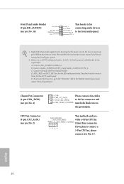
... a 24-pin ATX power connector. To clear CMOS, take out the CMOS battery and short the Clear CMOS Pad. H110M-HDS ATX Power Connector (24-pin ATXPWR1) (see p.6, No. 8) 5 1 8 4 This motherboard provides a 8-pin ATX 12V power connector. 1 PCICLK FRAME PCIRST# LAD3 +3V LAD0 +3VSB GND This connector supports Trusted Platform Module (TPM) system...
... a 24-pin ATX power connector. To clear CMOS, take out the CMOS battery and short the Clear CMOS Pad. H110M-HDS ATX Power Connector (24-pin ATXPWR1) (see p.6, No. 8) 5 1 8 4 This motherboard provides a 8-pin ATX 12V power connector. 1 PCICLK FRAME PCIRST# LAD3 +3V LAD0 +3VSB GND This connector supports Trusted Platform Module (TPM) system...
User Manual
Page 27
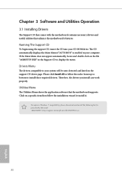
...click on the support CD driver page. Utilities Menu The Utilities Menu shows the application software that enhance the motherboard's features. Therefore, the drivers you install can work properly. Chapter 3 Software and Utilities Operation 3.1 Installing Drivers The ...Support CD that comes with the motherboard contains necessary drivers and useful utilities that the motherboard supports. To improve Windows 7 compatibility, please download and install the following hot fix provided by Microsoft...
...click on the support CD driver page. Utilities Menu The Utilities Menu shows the application software that enhance the motherboard's features. Therefore, the drivers you install can work properly. Chapter 3 Software and Utilities Operation 3.1 Installing Drivers The ...Support CD that comes with the motherboard contains necessary drivers and useful utilities that the motherboard supports. To improve Windows 7 compatibility, please download and install the following hot fix provided by Microsoft...
User Manual
Page 28
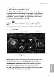
...information panel below displays the relative information. H110M-HDS 3.2 ASRock Live Update & APP Shop The ASRock Live Update & APP Shop is an online store for purchasing and downloading software applications for your motherboard up to date simply with a few clicks. With ASRock APP Shop, you can quickly and ... . 23 English Hot News: The hot news section displays the various latest news. You can optimize your system and keep your ASRock computer. Information Panel: The information panel in the center displays data about the currently selected category and allows users to perform job...
...information panel below displays the relative information. H110M-HDS 3.2 ASRock Live Update & APP Shop The ASRock Live Update & APP Shop is an online store for purchasing and downloading software applications for your motherboard up to date simply with a few clicks. With ASRock APP Shop, you can quickly and ... . 23 English Hot News: The hot news section displays the various latest news. You can optimize your system and keep your ASRock computer. Information Panel: The information panel in the center displays data about the currently selected category and allows users to perform job...
User Manual
Page 34
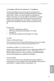
...A Windows® 7 installation disk or USB drive • USB 3.0 drivers (included in the ASRock Support CD or website) • A Windows® PC • Win7 USB Patcher (included in the ASRock Support CD or website) Scenarios You have an ODD and PS/2 ports: If there is an ...You only have an optical disc drive, please find it difficult to disabled after the installation. H110M-HDS 3.3 Enabling USB Ports for Windows® 7 Installation Intel® Braswell and Skylake has removed their motherboard won't work. In order for the USB ports to function properly, please create a Windows®...
...A Windows® 7 installation disk or USB drive • USB 3.0 drivers (included in the ASRock Support CD or website) • A Windows® PC • Win7 USB Patcher (included in the ASRock Support CD or website) Scenarios You have an ODD and PS/2 ports: If there is an ...You only have an optical disc drive, please find it difficult to disabled after the installation. H110M-HDS 3.3 Enabling USB Ports for Windows® 7 Installation Intel® Braswell and Skylake has removed their motherboard won't work. In order for the USB ports to function properly, please create a Windows®...
User Manual
Page 43
...] is exceeded. Long Duration Maintained Configure the period of time until the CPU ratio is lowered when the Long Duration Power Limit is selected, the motherboard will be lowered immediately. When the limit is exceeded, the CPU ratio will detect the memory module(s) inserted and assign the appropriate frequency automatically. DRAM...
...] is exceeded. Long Duration Maintained Configure the period of time until the CPU ratio is lowered when the Long Duration Power Limit is selected, the motherboard will be lowered immediately. When the limit is exceeded, the CPU ratio will detect the memory module(s) inserted and assign the appropriate frequency automatically. DRAM...
User Manual
Page 63
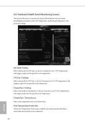
... temperature source for CPU Fan, or choose Customize to monitor the status of the hardware on your system, including the parameters of the CPU temperature, motherboard temperature, fan speed and voltage. Fan-Tastic Tuning Select a fan mode for CPU Fans, or choose Customize to set 5 CPU temperatures and assign a ...respective fan speed for each temperature. Over Temperature Protection When Over Temperature Protection is enabled, the system automatically shuts down when the motherboard is overheated. 58 English CPU Fan 1 Setting Select a fan mode for Chassis Fan.
... temperature source for CPU Fan, or choose Customize to monitor the status of the hardware on your system, including the parameters of the CPU temperature, motherboard temperature, fan speed and voltage. Fan-Tastic Tuning Select a fan mode for CPU Fans, or choose Customize to set 5 CPU temperatures and assign a ...respective fan speed for each temperature. Over Temperature Protection When Over Temperature Protection is enabled, the system automatically shuts down when the motherboard is overheated. 58 English CPU Fan 1 Setting Select a fan mode for Chassis Fan.

