
User Manual
Page 4
... 1 1.2 Specifications 2 1.3 Motherboard Layout 6 1.4 I/O Panel 8 Chapter 2 Installation 10 2.1 Installing the CPU 11 2.2 Installing the CPU Fan and Heatsink 14 2.3 Installing Memory Modules (DIMM) 15 2.4 Expansion Slots (PCI Express Slots) 17 2.5 Onboard Headers and Connectors 18 Chapter 3 Software and Utilities Operation 22 3.1 Installing Drivers 22 3.2 ASRock Live Update & APP Shop 23 3.2.1 UI Overview 23 3.2.2 Apps 24 3.2.3 BIOS & Drivers 27 3.2.4 Setting 28 3.3 Enabling USB Ports for Windows® 7 Installation 29 Chapter 4 UEFI SETUP UTILITY 32...
... 1 1.2 Specifications 2 1.3 Motherboard Layout 6 1.4 I/O Panel 8 Chapter 2 Installation 10 2.1 Installing the CPU 11 2.2 Installing the CPU Fan and Heatsink 14 2.3 Installing Memory Modules (DIMM) 15 2.4 Expansion Slots (PCI Express Slots) 17 2.5 Onboard Headers and Connectors 18 Chapter 3 Software and Utilities Operation 22 3.1 Installing Drivers 22 3.2 ASRock Live Update & APP Shop 23 3.2.1 UI Overview 23 3.2.2 Apps 24 3.2.3 BIOS & Drivers 27 3.2.4 Setting 28 3.3 Enabling USB Ports for Windows® 7 Installation 29 Chapter 4 UEFI SETUP UTILITY 32...
User Manual
Page 6
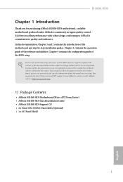
... are using. Chapter 4 contains the configuration guide of the software and utilities. In case any modifications of the motherboard and step-by-step installation guides. ASRock website http://www.asrock.com. 1.1 Package Contents • ASRock H110M-HDS Motherboard (Micro ATX Form Factor) • ASRock H110M-HDS Quick Installation Guide • ASRock H110M-HDS Support CD • 2 x Serial ATA (SATA) Data Cables (Optional) • 1 x I/O Panel Shield 1 English In this documentation will be available on ASRock's website as well. Because the motherboard specifications and the BIOS...
... are using. Chapter 4 contains the configuration guide of the software and utilities. In case any modifications of the motherboard and step-by-step installation guides. ASRock website http://www.asrock.com. 1.1 Package Contents • ASRock H110M-HDS Motherboard (Micro ATX Form Factor) • ASRock H110M-HDS Quick Installation Guide • ASRock H110M-HDS Support CD • 2 x Serial ATA (SATA) Data Cables (Optional) • 1 x I/O Panel Shield 1 English In this documentation will be available on ASRock's website as well. Because the motherboard specifications and the BIOS...
User Manual
Page 8
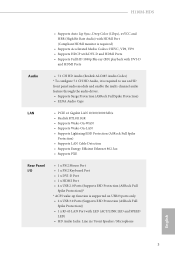
...) • Supports LAN Cable Detection • Supports Energy Efficient Ethernet 802.3az • Supports PXE Rear Panel I/O • 1 x PS/2 Mouse Port • 1 x PS/2 Keyboard Port • 1 x DVI-D Port • 1 x HDMI Port • 4 x USB 2.0 Ports (Supports ESD Protection (ASRock Full Spike Protection))* * ACPI wake-up function is supported on USB23 ports only. • 2 x USB 3.0 Ports (Supports ESD Protection (ASRock Full Spike Protection)) • 1 x RJ-45 LAN Port with LED (ACT/LINK LED and SPEED LED) • HD Audio Jacks: Line in / Front Speaker / Microphone...
...) • Supports LAN Cable Detection • Supports Energy Efficient Ethernet 802.3az • Supports PXE Rear Panel I/O • 1 x PS/2 Mouse Port • 1 x PS/2 Keyboard Port • 1 x DVI-D Port • 1 x HDMI Port • 4 x USB 2.0 Ports (Supports ESD Protection (ASRock Full Spike Protection))* * ACPI wake-up function is supported on USB23 ports only. • 2 x USB 3.0 Ports (Supports ESD Protection (ASRock Full Spike Protection)) • 1 x RJ-45 LAN Port with LED (ACT/LINK LED and SPEED LED) • HD Audio Jacks: Line in / Front Speaker / Microphone...
User Manual
Page 9
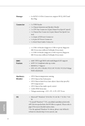
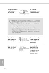
...Connector • 1 x Front Panel Audio Connector • 1 x USB 2.0 Header (Supports 2 USB 2.0 ports) (Supports ESD Protection (ASRock Full Spike Protection)) • 1 x USB 3.0 Header (Supports 2 USB 3.0 ports) (Supports ESD Protection (ASRock Full Spike Protection)) BIOS Feature • AMI UEFI Legal BIOS with xHCI drivers packed into the ISO file is required. bit * To install Windows® 7 OS, a modified installation disk with multilingual GUI support • ACPI 5.0 Compliant wake up events • SMBIOS 2.7 Support • CPU, GT_CPU, DRAM, PCH 1.0V, VCCIO, VCCSA Voltage...
...Connector • 1 x Front Panel Audio Connector • 1 x USB 2.0 Header (Supports 2 USB 2.0 ports) (Supports ESD Protection (ASRock Full Spike Protection)) • 1 x USB 3.0 Header (Supports 2 USB 3.0 ports) (Supports ESD Protection (ASRock Full Spike Protection)) BIOS Feature • AMI UEFI Legal BIOS with xHCI drivers packed into the ISO file is required. bit * To install Windows® 7 OS, a modified installation disk with multilingual GUI support • ACPI 5.0 Compliant wake up events • SMBIOS 2.7 Support • CPU, GT_CPU, DRAM, PCH 1.0V, VCCIO, VCCSA Voltage...
User Manual
Page 12
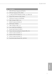
No. Description 1 ATX 12V Power Connector (ATX12V1) 2 CPU Fan Connector (CPU_FAN1) 3 2 x 288-pin DDR4 DIMM Slots (DDR4_A1, DDR4_B1) 4 Chassis Fan Connector (CHA_FAN1) 5 ATX Power Connector (ATXPWR1) 6 USB 3.0 Header (USB3_3_4) 7 SATA3 Connector (SATA3_0) 8 TPM Header (TPMS1) 9 USB 2.0 Header (USB_4_5) 10 Clear CMOS Pad (CLRMOS1) 11 System Panel Header (PANEL1) 12 Chassis Intrusion and Speaker Header (SPK_CI1) 13 SATA3 Connector (SATA3_1) 14 SATA3 Connector (SATA3_2) 15 SATA3 Connector (SATA3_3) 16 Front Panel Audio Header (HD_AUDIO1) H110M-HDS English 7
No. Description 1 ATX 12V Power Connector (ATX12V1) 2 CPU Fan Connector (CPU_FAN1) 3 2 x 288-pin DDR4 DIMM Slots (DDR4_A1, DDR4_B1) 4 Chassis Fan Connector (CHA_FAN1) 5 ATX Power Connector (ATXPWR1) 6 USB 3.0 Header (USB3_3_4) 7 SATA3 Connector (SATA3_0) 8 TPM Header (TPMS1) 9 USB 2.0 Header (USB_4_5) 10 Clear CMOS Pad (CLRMOS1) 11 System Panel Header (PANEL1) 12 Chassis Intrusion and Speaker Header (SPK_CI1) 13 SATA3 Connector (SATA3_1) 14 SATA3 Connector (SATA3_2) 15 SATA3 Connector (SATA3_3) 16 Front Panel Audio Header (HD_AUDIO1) H110M-HDS English 7
User Manual
Page 22
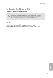
PCIe slots: PCIE1 (PCIe 2.0 x1 slot) is used for the card before you start the installation. Please read the documentation of the expansion card and make sure that the power supply is switched off or the power cord is used for PCI Express x1 lane width cards PCIE2 (PCIe 3.0 x16 slot) is unplugged. Before installing an expansion card, please make necessary hardware settings for PCI Express x16 lane width graphics cards. 17 English H110M-HDS 2.4 Expansion Slots (PCI Express Slots) There are 2 PCI Express slots on the motherboard.
PCIe slots: PCIE1 (PCIe 2.0 x1 slot) is used for the card before you start the installation. Please read the documentation of the expansion card and make sure that the power supply is switched off or the power cord is used for PCI Express x1 lane width cards PCIE2 (PCIe 3.0 x16 slot) is unplugged. Before installing an expansion card, please make necessary hardware settings for PCI Express x16 lane width graphics cards. 17 English H110M-HDS 2.4 Expansion Slots (PCI Express Slots) There are 2 PCI Express slots on the motherboard.
User Manual
Page 23
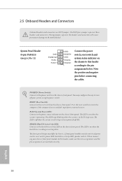
... chassis front panel. The LED is on the chassis front panel. A front panel module mainly consists of power switch, reset switch, power LED, hard drive activity LED, speaker and etc. Do NOT place jumper caps over the headers and connectors will cause permanent damage to perform a normal restart. PWRBTN (Power Switch): Connect to this header, make sure the wire assignments and the pin assignments are NOT jumpers. HDLED (Hard Drive Activity LED): Connect to the reset switch on the chassis front panel. RESET (Reset Switch): Connect to the hard drive activity LED...
... chassis front panel. The LED is on the chassis front panel. A front panel module mainly consists of power switch, reset switch, power LED, hard drive activity LED, speaker and etc. Do NOT place jumper caps over the headers and connectors will cause permanent damage to perform a normal restart. PWRBTN (Power Switch): Connect to this header, make sure the wire assignments and the pin assignments are NOT jumpers. HDLED (Hard Drive Activity LED): Connect to the reset switch on the chassis front panel. RESET (Reset Switch): Connect to the hard drive activity LED...
User Manual
Page 24
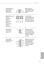
... four SATA3 connectors support SATA data cables for internal storage devices with up to this motherboard. H110M-HDS Chassis Intrusion and Speaker Header (7-pin SPK_CI1) (see p.6, No. 12) 1 SIGNAL GND DUMMY Please connect the +5V chassis intrusion and the DUMMY chassis speaker to 6.0 Gb/s data transfer rate. 1 USB_PWR PP+ GND USB_PWR PP+ GND DUMMY Besides four USB 2.0 ports on the I /O panel, there IntA_PB_SSRX+ GND is one header on this DUMMY SPEAKER header. Serial ATA3 Connectors (SATA3_0...
... four SATA3 connectors support SATA data cables for internal storage devices with up to this motherboard. H110M-HDS Chassis Intrusion and Speaker Header (7-pin SPK_CI1) (see p.6, No. 12) 1 SIGNAL GND DUMMY Please connect the +5V chassis intrusion and the DUMMY chassis speaker to 6.0 Gb/s data transfer rate. 1 USB_PWR PP+ GND USB_PWR PP+ GND DUMMY Besides four USB 2.0 ports on the I /O panel, there IntA_PB_SSRX+ GND is one header on this DUMMY SPEAKER header. Serial ATA3 Connectors (SATA3_0...
User Manual
Page 25
... D This header is for the HD audio panel only. MIC2_L 1 1. D. High Definition Audio supports Jack Sensing, but the panel wire on the chassis must support HDA to the ground pin. Chassis Fan Connector (4-pin CHA_FAN1) (see p.6, No. 4) GND FAN_VOLTAGE CHA_FAN_SPEED Please connect fan cables to the fan connector and FAN_SPEED_CONTROL match the black wire to function correctly. FAN_VOLTAGE CPU_FAN_SPEED vides a 4-Pin CPU fan GND FAN_SPEED_CONTROL (Quiet Fan) connector. 1 2 34 If you use an AC'97 audio panel, please install it to Pin...
... D This header is for the HD audio panel only. MIC2_L 1 1. D. High Definition Audio supports Jack Sensing, but the panel wire on the chassis must support HDA to the ground pin. Chassis Fan Connector (4-pin CHA_FAN1) (see p.6, No. 4) GND FAN_VOLTAGE CHA_FAN_SPEED Please connect fan cables to the fan connector and FAN_SPEED_CONTROL match the black wire to function correctly. FAN_VOLTAGE CPU_FAN_SPEED vides a 4-Pin CPU fan GND FAN_SPEED_CONTROL (Quiet Fan) connector. 1 2 34 If you use an AC'97 audio panel, please install it to Pin...

User Manual
Page 26
.... 5) 1 13 12 24 This motherboard provides a 24-pin ATX power connector. H110M-HDS ATX Power Connector (24-pin ATXPWR1) (see p.6, No. 8) 5 1 8 4 This motherboard provides a 8-pin ATX 12V power connector. 1 PCICLK FRAME PCIRST# LAD3 +3V LAD0 +3VSB GND This connector supports Trusted Platform Module (TPM) system, GND SMB_CLK_MAIN which can securely store keys, SMB_DATA_MAIN digital certificates, passwords, LAD2 LAD1 and data. To use a 20-pin ATX power supply, please plug it along Pin 1 and Pin 13. Clear CMOS Pad (CLRMOS1) (see...
.... 5) 1 13 12 24 This motherboard provides a 24-pin ATX power connector. H110M-HDS ATX Power Connector (24-pin ATXPWR1) (see p.6, No. 8) 5 1 8 4 This motherboard provides a 8-pin ATX 12V power connector. 1 PCICLK FRAME PCIRST# LAD3 +3V LAD0 +3VSB GND This connector supports Trusted Platform Module (TPM) system, GND SMB_CLK_MAIN which can securely store keys, SMB_DATA_MAIN digital certificates, passwords, LAD2 LAD1 and data. To use a 20-pin ATX power supply, please plug it along Pin 1 and Pin 13. Clear CMOS Pad (CLRMOS1) (see...
User Manual
Page 27
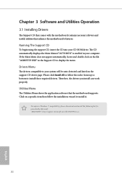
... automatically displays the Main Menu if "AUTORUN" is enabled in the Support CD to your CD-ROM drive. Chapter 3 Software and Utilities Operation 3.1 Installing Drivers The Support CD that comes with the motherboard contains necessary drivers and useful utilities that the motherboard supports. If the Main Menu does not appear automatically, locate and double click on the support CD driver page. Utilities Menu The Utilities Menu shows the application software that enhance the motherboard's features. Therefore, the drivers you install can work...
... automatically displays the Main Menu if "AUTORUN" is enabled in the Support CD to your CD-ROM drive. Chapter 3 Software and Utilities Operation 3.1 Installing Drivers The Support CD that comes with the motherboard contains necessary drivers and useful utilities that the motherboard supports. If the Main Menu does not appear automatically, locate and double click on the support CD driver page. Utilities Menu The Utilities Menu shows the application software that enhance the motherboard's features. Therefore, the drivers you install can work...
User Manual
Page 28
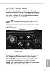
... your ASRock computer. H110M-HDS 3.2 ASRock Live Update & APP Shop The ASRock Live Update & APP Shop is an online store for purchasing and downloading software applications for your desktop to access ASRock Live Update & APP Shop *You need to be connected to the Internet to date simply with a few clicks. You can optimize your system and keep your motherboard up to download apps from the ASRock Live Update...
... your ASRock computer. H110M-HDS 3.2 ASRock Live Update & APP Shop The ASRock Live Update & APP Shop is an online store for purchasing and downloading software applications for your desktop to access ASRock Live Update & APP Shop *You need to be connected to the Internet to date simply with a few clicks. You can optimize your system and keep your motherboard up to download apps from the ASRock Live Update...
User Manual
Page 34
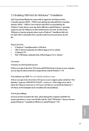
H110M-HDS 3.3 Enabling USB Ports for Windows® 7 Installation Intel® Braswell and Skylake has removed their motherboard won't work. Due to that fact that XHCI is not included in UEFI SETUP UTILITY > Advanced > USB Configuration, which allows the USB port to function properly, please create a Windows® 7 installation disk with the "Win7 USB Patcher". Requirements • A Windows® 7 installation disk or USB drive • USB 3.0 drivers (included in the ASRock Support CD or website) • A Windows® PC • Win7 USB Patcher...
H110M-HDS 3.3 Enabling USB Ports for Windows® 7 Installation Intel® Braswell and Skylake has removed their motherboard won't work. Due to that fact that XHCI is not included in UEFI SETUP UTILITY > Advanced > USB Configuration, which allows the USB port to function properly, please create a Windows® 7 installation disk with the "Win7 USB Patcher". Requirements • A Windows® 7 installation disk or USB drive • USB 3.0 drivers (included in the ASRock Support CD or website) • A Windows® PC • Win7 USB Patcher...
User Manual
Page 35
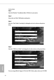
If you are using ASRock's Support CD for the USB 3.0 driver, please select your system. Instructions Step 1 Insert the Windows® 7 installation disk or USB drive to your CD-ROM. 30 English Step 2 Extract the tool (Win7 USB Patcher) and launch it. Step 4 Select the "USB Driver Folder" by clicking the red circle as shown as the picture below . Step 3 Select the "Win7 Folder" from Step1 by clicking the red circle as shown as the picture below .
If you are using ASRock's Support CD for the USB 3.0 driver, please select your system. Instructions Step 1 Insert the Windows® 7 installation disk or USB drive to your CD-ROM. 30 English Step 2 Extract the tool (Win7 USB Patcher) and launch it. Step 4 Select the "USB Driver Folder" by clicking the red circle as shown as the picture below . Step 3 Select the "Win7 Folder" from Step1 by clicking the red circle as shown as the picture below .
User Manual
Page 53
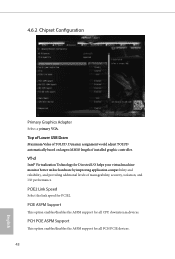
... Support This option enables/disables the ASPM support for PCIE2. PCIE ASPM Support This option enables/disables the ASPM support for Directed I/O helps your virtual machine monitor better utilize hardware by improving application compatibility and reliability, and providing additional levels of installed graphic controller. Dynamic assignment would adjust TOLUD automatically based on largest MMIO length of manageability, security, isolation, and I/O performance. 4.6.2 Chipset Configuration Primary Graphics Adapter Select a primary VGA. Top of Lower USB Dram...
... Support This option enables/disables the ASPM support for PCIE2. PCIE ASPM Support This option enables/disables the ASPM support for Directed I/O helps your virtual machine monitor better utilize hardware by improving application compatibility and reliability, and providing additional levels of installed graphic controller. Dynamic assignment would adjust TOLUD automatically based on largest MMIO length of manageability, security, isolation, and I/O performance. 4.6.2 Chipset Configuration Primary Graphics Adapter Select a primary VGA. Top of Lower USB Dram...
User Manual
Page 54
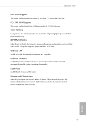
.... PCH DMI ASPM Support This option enables/disables the ASPM support for all times. Onboard LAN Enable or disable the onboard network interface controller. If [Power Off] is allocated to disable the integrated graphics when an external graphics card is installed. IGPU Multi-Monitor Select disable to the integrated graphics processor when the system boots up when the power recovers. 49 English Onboard HD Audio Enable/disable onboard HD audio. Front Panel Enable/disable front panel HD audio. H110M-HDS DMI ASPM Support This option enables/disables the control of ASPM on...
.... PCH DMI ASPM Support This option enables/disables the ASPM support for all times. Onboard LAN Enable or disable the onboard network interface controller. If [Power Off] is allocated to disable the integrated graphics when an external graphics card is installed. IGPU Multi-Monitor Select disable to the integrated graphics processor when the system boots up when the power recovers. 49 English Onboard HD Audio Enable/disable onboard HD audio. Front Panel Enable/disable front panel HD audio. H110M-HDS DMI ASPM Support This option enables/disables the control of ASPM on...
User Manual
Page 60
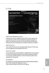
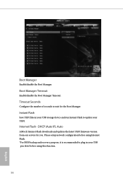
4.7 Tools H110M-HDS OMG (Online Management Guard) Administrators are required. You may schedule the starting and ending hours of internet access granted to use this tool. 55 English Please setup network configuration before using UEFI Tech Service. Boot Manager Boot Manager is a handy tool in the UEFI that installs the LAN driver to establish an internet curfew or restrict internet access at specified times via an USB storage device, then downloads and installs the...
4.7 Tools H110M-HDS OMG (Online Management Guard) Administrators are required. You may schedule the starting and ending hours of internet access granted to use this tool. 55 English Please setup network configuration before using UEFI Tech Service. Boot Manager Boot Manager is a handy tool in the UEFI that installs the LAN driver to establish an internet curfew or restrict internet access at specified times via an USB storage device, then downloads and installs the...
User Manual
Page 61
... setup network configuration before using Internet Flash. *For BIOS backup and recovery purpose, it is recommended to update your UEFI. Internet Flash - Instant Flash Save UEFI files in your USB storage device and run Instant Flash to plug in your USB pen drive before using this function. 56 English Boot Manager Enable/disable the Boot Manager. Boot Manager Timeout Enable/disable the Boot Manager Timeout. DHCP (Auto IP), Auto ASRock Internet Flash downloads and updates the latest UEFI firmware version from our servers for the Boot Manager. Timeout Seconds Configure...
... setup network configuration before using Internet Flash. *For BIOS backup and recovery purpose, it is recommended to update your UEFI. Internet Flash - Instant Flash Save UEFI files in your USB storage device and run Instant Flash to plug in your USB pen drive before using this function. 56 English Boot Manager Enable/disable the Boot Manager. Boot Manager Timeout Enable/disable the Boot Manager Timeout. DHCP (Auto IP), Auto ASRock Internet Flash downloads and updates the latest UEFI firmware version from our servers for the Boot Manager. Timeout Seconds Configure...
User Manual
Page 62
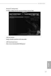
UEFI Download Server Select a server to configure internet connection settings for Internet Flash. H110M-HDS Network Configuration Use this to download the UEFI firmware. 57 English Internet Setting Enable or disable sound effects in the setup utility.
UEFI Download Server Select a server to configure internet connection settings for Internet Flash. H110M-HDS Network Configuration Use this to download the UEFI firmware. 57 English Internet Setting Enable or disable sound effects in the setup utility.
User Manual
Page 65
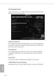
... option to change the password for Windows 8.1 Secure Boot. Only the administrator has authority to use discrete TPM Module. 60 English Leave it blank and press enter to enable or disable support for the user account. Disable this item to remove the password. Leave it blank and press enter to change the password for the system. Intel(R) Platform Trust Technology Enable/disable Intel PTT in the UEFI Setup Utility. User Password Set or change the settings in the UEFI Setup Utility...
... option to change the password for Windows 8.1 Secure Boot. Only the administrator has authority to use discrete TPM Module. 60 English Leave it blank and press enter to enable or disable support for the user account. Disable this item to remove the password. Leave it blank and press enter to change the password for the system. Intel(R) Platform Trust Technology Enable/disable Intel PTT in the UEFI Setup Utility. User Password Set or change the settings in the UEFI Setup Utility...


