
User Manual
Page 12
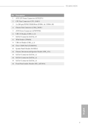
Description 1 ATX 12V Power Connector (ATX12V1) 2 CPU Fan Connector (CPU_FAN1) 3 2 x 288-pin DDR4 DIMM Slots (DDR4_A1, DDR4_B1) 4 Chassis Fan Connector (CHA_FAN1) 5 ATX Power Connector (ATXPWR1) 6 USB 3.0 Header (USB3_3_4) 7 SATA3 Connector (SATA3_0) 8 TPM Header (TPMS1) 9 USB 2.0 Header (USB_4_5) 10 Clear CMOS Pad (CLRMOS1) 11 System Panel Header (PANEL1) 12 Chassis Intrusion and Speaker Header (SPK_CI1) 13 SATA3 Connector (SATA3_1) 14 SATA3 Connector (SATA3_2) 15 SATA3 Connector (SATA3_3) 16 Front Panel Audio Header (HD_AUDIO1) H110M-HDS English 7 No.
Description 1 ATX 12V Power Connector (ATX12V1) 2 CPU Fan Connector (CPU_FAN1) 3 2 x 288-pin DDR4 DIMM Slots (DDR4_A1, DDR4_B1) 4 Chassis Fan Connector (CHA_FAN1) 5 ATX Power Connector (ATXPWR1) 6 USB 3.0 Header (USB3_3_4) 7 SATA3 Connector (SATA3_0) 8 TPM Header (TPMS1) 9 USB 2.0 Header (USB_4_5) 10 Clear CMOS Pad (CLRMOS1) 11 System Panel Header (PANEL1) 12 Chassis Intrusion and Speaker Header (SPK_CI1) 13 SATA3 Connector (SATA3_1) 14 SATA3 Connector (SATA3_2) 15 SATA3 Connector (SATA3_3) 16 Front Panel Audio Header (HD_AUDIO1) H110M-HDS English 7 No.

User Manual
Page 26
... 21 ATX 12V Power Connector (8-pin ATX12V1) (see p.6, No. 1) TPM Header (17-pin TPMS1) (see p.6, No. 10) CLRMOS1 allows you to clear the data in CMOS. Clear CMOS Pad (CLRMOS1) (see p.6, No. 8) 5 1 8 4 This motherboard provides a 8-pin ATX 12V power connector. 1 PCICLK FRAME PCIRST# LAD3 +3V..., SERIRQ# GND protects digital identities, and ensures platform integrity. To clear CMOS, take out the CMOS battery and short the Clear CMOS Pad. To use a 20-pin ATX power supply, please plug it along Pin 1 and Pin 13. H110M-HDS ATX Power Connector (24-pin ATXPWR1) (see p.6, No. 5) ...
... 21 ATX 12V Power Connector (8-pin ATX12V1) (see p.6, No. 1) TPM Header (17-pin TPMS1) (see p.6, No. 10) CLRMOS1 allows you to clear the data in CMOS. Clear CMOS Pad (CLRMOS1) (see p.6, No. 8) 5 1 8 4 This motherboard provides a 8-pin ATX 12V power connector. 1 PCICLK FRAME PCIRST# LAD3 +3V..., SERIRQ# GND protects digital identities, and ensures platform integrity. To clear CMOS, take out the CMOS battery and short the Clear CMOS Pad. To use a 20-pin ATX power supply, please plug it along Pin 1 and Pin 13. H110M-HDS ATX Power Connector (24-pin ATXPWR1) (see p.6, No. 5) ...
User Manual
Page 66
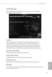
H110M-HDS 4.10 Boot Screen This section displays the available devices on your computer's boot time. Bootup Num-Lock Select whether Num Lock should be turned on ... of seconds to configure the boot settings and the boot priority. Please note that the only way to enter this UEFI Setup Utility is to Clear CMOS or run the Restart to be waked up . Boot From Onboard LAN Allow the system to UEFI utility in Windows. Please notice that Ultra Fast...
H110M-HDS 4.10 Boot Screen This section displays the available devices on your computer's boot time. Bootup Num-Lock Select whether Num Lock should be turned on ... of seconds to configure the boot settings and the boot priority. Please note that the only way to enter this UEFI Setup Utility is to Clear CMOS or run the Restart to be waked up . Boot From Onboard LAN Allow the system to UEFI utility in Windows. Please notice that Ultra Fast...

