

User Manual
Page 3
... 1 Introduction 1 1.1 Package Contents 1 1.2 Specifications 2 1.3 Motherboard Layout 5 1.4 I/O Panel 7 Chapter 2 Installation 9 2.1 Installing the CPU 10 2.2 Installing the CPU Fan and Heatsink 13 2.3 Installing Memory Modules (DIMM) 14 2.4 Expansion Slots (PCI Express Slots) 16 2.5 Onboard Headers and Connectors 17 Chapter 3 Software and Utilities Operation 21 3.1 Installing Drivers 21 3.2 ASRock Live Update & APP Shop 22 3.2.1 UI Overview...
... 1 Introduction 1 1.1 Package Contents 1 1.2 Specifications 2 1.3 Motherboard Layout 5 1.4 I/O Panel 7 Chapter 2 Installation 9 2.1 Installing the CPU 10 2.2 Installing the CPU Fan and Heatsink 13 2.3 Installing Memory Modules (DIMM) 14 2.4 Expansion Slots (PCI Express Slots) 16 2.5 Onboard Headers and Connectors 17 Chapter 3 Software and Utilities Operation 21 3.1 Installing Drivers 21 3.2 ASRock Live Update & APP Shop 22 3.2.1 UI Overview...
User Manual
Page 7
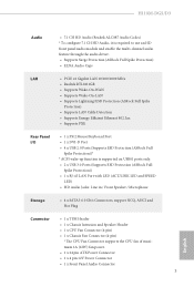
H110M-DGS/D3 Audio • 7.1 CH HD Audio (Realtek ALC887 Audio Codec) * To configure 7.1 CH HD Audio, it is required to use an HD front panel audio module and enable the multi-channel audio feature through the audio driver. • Supports Surge Protection (ASRock Full Spike Protection) • ELNA Audio Caps LAN • PCIE x1...
H110M-DGS/D3 Audio • 7.1 CH HD Audio (Realtek ALC887 Audio Codec) * To configure 7.1 CH HD Audio, it is required to use an HD front panel audio module and enable the multi-channel audio feature through the audio driver. • Supports Surge Protection (ASRock Full Spike Protection) • ELNA Audio Caps LAN • PCIE x1...

User Manual
Page 10
Description 1 ATX 12V Power Connector (ATX12V1) 2 CPU Fan Connector (CPU_FAN1) 3 2 x 240-pin DDR3/DDR3L DIMM Slots (DDR3_A1, DDR3_B1) 4 Chassis Fan Connector (CHA_FAN1) 5 ATX Power Connector (ATXPWR1) 6 USB 3.0 Header (USB3_3_4) 7 TPM Header (TPMS1) 8 USB 2.0 Header (USB4_5) 9 Clear CMOS Pad (CLRMOS1) 10 System Panel Header (PANEL1) 11 Chassis Intrusion and Speaker Header (SPK_CI1) 12 SATA3 Connector (SATA3_0) 13 SATA3 Connector (SATA3_1) 14 SATA3 Connector (SATA3_2) 15 SATA3 Connector (SATA3_3) 16 Front Panel Audio Header (HD_AUDIO1) 6 English No.
Description 1 ATX 12V Power Connector (ATX12V1) 2 CPU Fan Connector (CPU_FAN1) 3 2 x 240-pin DDR3/DDR3L DIMM Slots (DDR3_A1, DDR3_B1) 4 Chassis Fan Connector (CHA_FAN1) 5 ATX Power Connector (ATXPWR1) 6 USB 3.0 Header (USB3_3_4) 7 TPM Header (TPMS1) 8 USB 2.0 Header (USB4_5) 9 Clear CMOS Pad (CLRMOS1) 10 System Panel Header (PANEL1) 11 Chassis Intrusion and Speaker Header (SPK_CI1) 12 SATA3 Connector (SATA3_0) 13 SATA3 Connector (SATA3_1) 14 SATA3 Connector (SATA3_2) 15 SATA3 Connector (SATA3_3) 16 Front Panel Audio Header (HD_AUDIO1) 6 English No.

User Manual
Page 21
...). PWRBTN (Power Switch): Connect to the power status indicator on the chassis front panel. Do NOT place jumper caps over the headers and connectors will cause permanent damage to perform a normal restart. H110M-DGS/D3 2.5 Onboard Headers and Connectors Onboard headers and connectors are matched correctly. PLED (System Power LED): Connect to the power switch on...
...). PWRBTN (Power Switch): Connect to the power status indicator on the chassis front panel. Do NOT place jumper caps over the headers and connectors will cause permanent damage to perform a normal restart. H110M-DGS/D3 2.5 Onboard Headers and Connectors Onboard headers and connectors are matched correctly. PLED (System Power LED): Connect to the power switch on...
User Manual
Page 22
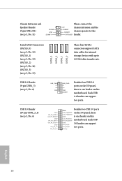
...1 USB_PWR PP+ GND USB_PWR PP+ GND DUMMY Besides four USB 2.0 ports on the I /O panel, there IntA_PB_SSRX+ GND is one header on this DUMMY SPEAKER header. Each USB 2.0 header can support...Connectors (SATA3_0) (see p.5, No. 12) (SATA3_1) (see p.5, No. 13) (SATA3_2) (see p.5, No. 14) (SATA3_3) (see p.5, No. 15) USB 2.0 Header (9-pin USB4_5) (see p.5, No. 6) Vbus IntA_PA_SSRXIntA_PA_SSRX+ GND IntA_PA_SSTXIntA_PA_SSTX+ GND IntA_PA_DIntA_PA_D+ Besides two USB 3.0 ports Vbus IntA_PB_SSRX- Each USB GND IntA_PB_DIntA_PB_D+ Dummy 3.0 header can support two ports. on the I /O panel...
...1 USB_PWR PP+ GND USB_PWR PP+ GND DUMMY Besides four USB 2.0 ports on the I /O panel, there IntA_PB_SSRX+ GND is one header on this DUMMY SPEAKER header. Each USB 2.0 header can support...Connectors (SATA3_0) (see p.5, No. 12) (SATA3_1) (see p.5, No. 13) (SATA3_2) (see p.5, No. 14) (SATA3_3) (see p.5, No. 15) USB 2.0 Header (9-pin USB4_5) (see p.5, No. 6) Vbus IntA_PA_SSRXIntA_PA_SSRX+ GND IntA_PA_SSTXIntA_PA_SSTX+ GND IntA_PA_DIntA_PA_D+ Besides two USB 3.0 ports Vbus IntA_PB_SSRX- Each USB GND IntA_PB_DIntA_PB_D+ Dummy 3.0 header can support two ports. on the I /O panel...
User Manual
Page 23
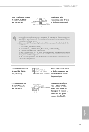
.... Please follow the instructions in the Realtek Control panel and adjust "Recording Volume". B. CPU Fan Connector (4-pin CPU_FAN1) (see p.5, No. 4) GND FAN_VOLTAGE CHA_FAN_SPEED Please connect fan cables to the fan connector and FAN_SPEED_CONTROL match the black wire to the front audio panel. English 19 H110M-DGS/D3 Front Panel Audio Header (9-pin HD_AUDIO1) (see p.5, No. 16) OUT_RET...
.... Please follow the instructions in the Realtek Control panel and adjust "Recording Volume". B. CPU Fan Connector (4-pin CPU_FAN1) (see p.5, No. 4) GND FAN_VOLTAGE CHA_FAN_SPEED Please connect fan cables to the fan connector and FAN_SPEED_CONTROL match the black wire to the front audio panel. English 19 H110M-DGS/D3 Front Panel Audio Header (9-pin HD_AUDIO1) (see p.5, No. 16) OUT_RET...

