
User Manual
Page 3
... Contents 4 1.2 Specifications 4 1.3 Motherboard Layout (GE Pro-M 6 1.4 Motherboard Layout (GE Pro-HT 7 1.5 ASRock I/OTM (GE Pro-M / GE Pro-HT 8 2 Installation 9 2.1 Screw Holes 9 2.2 Pre-installation Precautions 9 2.3 CPU Installation 9 2.4 Installation of Heatsink and CPU fan 10 2.5 Installation of Memory Modules (DIMM 10 2.6 Expansion Slots 11 2.7 ... 4.2 Support CD Information 19 4.2.1 Running Support CD 19 4.2.2 Drivers Menu 19 4.2.3 Utilities Menu 19 4.2.4 ASRock PC-DIY Live Demo Program 19 4.2.5 Contact Information 19 Appendix: Advanced BIOS Setup 20 1. Security Menu 23...
... Contents 4 1.2 Specifications 4 1.3 Motherboard Layout (GE Pro-M 6 1.4 Motherboard Layout (GE Pro-HT 7 1.5 ASRock I/OTM (GE Pro-M / GE Pro-HT 8 2 Installation 9 2.1 Screw Holes 9 2.2 Pre-installation Precautions 9 2.3 CPU Installation 9 2.4 Installation of Heatsink and CPU fan 10 2.5 Installation of Memory Modules (DIMM 10 2.6 Expansion Slots 11 2.7 ... 4.2 Support CD Information 19 4.2.1 Running Support CD 19 4.2.2 Drivers Menu 19 4.2.3 Utilities Menu 19 4.2.4 ASRock PC-DIY Live Demo Program 19 4.2.5 Contact Information 19 Appendix: Advanced BIOS Setup 20 1. Security Menu 23...

User Manual
Page 4
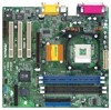
...information. 1.1 Package Contents ASRock GE Pro-M or GE Pro-HT motherboard (Micro ATX form factor: 9.6" x 9.6", 24.4 x 24.4 cm) ASRock GE Pro-M / GE Pro-HT Quick Installation Guide ASRock Intel-SiS Support CD...ASRock's consistently stringent quality control. Chapter 3 and 4 contain basic BIOS setup and Support CD information. For advanced users' reference, the Appendix appearing on GE Pro-HT motherboard: SiS 651HT chipsets , standard FSB 533 MHz, supports Hyper-Threading Technology (see CAUTION1); South Bridge: Supports USB 2.0, ATA 133 Clock Generator: 100 MHz - 200MHz Memory...
...information. 1.1 Package Contents ASRock GE Pro-M or GE Pro-HT motherboard (Micro ATX form factor: 9.6" x 9.6", 24.4 x 24.4 cm) ASRock GE Pro-M / GE Pro-HT Quick Installation Guide ASRock Intel-SiS Support CD...ASRock's consistently stringent quality control. Chapter 3 and 4 contain basic BIOS setup and Support CD information. For advanced users' reference, the Appendix appearing on GE Pro-HT motherboard: SiS 651HT chipsets , standard FSB 533 MHz, supports Hyper-Threading Technology (see CAUTION1); South Bridge: Supports USB 2.0, ATA 133 Clock Generator: 100 MHz - 200MHz Memory...

User Manual
Page 6
...27 20 AUDIO1 19 AUDIO CODEC Super I/O SiS 651 Chipset Accelerated Graphics Port PCI 1 PCI 2 11 2MB PCI 3 BIOS AMR1 GE Pro-M 26 18 8 7 01 23 01 23 SiS South Bridge CMOS 9 Battery CHA_FAN1 CLRCMOS1 FLOPPY1 IR1 COM1 USB45 SPEAKER1 RESET HDLED PANEL1... Primary IDE connector (IDE1, Blue) 8 Secondary IDE connector (IDE2, Black) 9 Chassis fan connector (CHA_FAN1) 10 Floppy connector (FLOPPY1) 11 Flash Memory 12 System panel connector (PANEL1) 13 USB 2.0 header (USB45) 14 Infrared module connector (IR1) 15 Chassis speaker connector (SPEAKER1) 16 South Bridge ...
...27 20 AUDIO1 19 AUDIO CODEC Super I/O SiS 651 Chipset Accelerated Graphics Port PCI 1 PCI 2 11 2MB PCI 3 BIOS AMR1 GE Pro-M 26 18 8 7 01 23 01 23 SiS South Bridge CMOS 9 Battery CHA_FAN1 CLRCMOS1 FLOPPY1 IR1 COM1 USB45 SPEAKER1 RESET HDLED PANEL1... Primary IDE connector (IDE1, Blue) 8 Secondary IDE connector (IDE2, Black) 9 Chassis fan connector (CHA_FAN1) 10 Floppy connector (FLOPPY1) 11 Flash Memory 12 System panel connector (PANEL1) 13 USB 2.0 header (USB45) 14 Infrared module connector (IR1) 15 Chassis speaker connector (SPEAKER1) 16 South Bridge ...

User Manual
Page 7
... 27 20 19 AUDIO1 AUDIO CODEC Super I/O SiS 651HT Chipset Accelerated Graphics Port PCI 1 PCI 2 11 2MB PCI 3 BIOS AMR1 GE Pro-HT 26 18 8 7 01 23 01 23 SiS South Bridge CMOS 9 Battery CHA_FAN1 CLRCMOS1 FLOPPY1 IR1 COM1 USB45 SPEAKER1 RESET HDLED ...7 Primary IDE connector (IDE1, Blue) 8 Secondary IDE connector (IDE2, Black) 9 Chassis fan connector (CHA_FAN1) 10 Floppy connector (FLOPPY1) 11 Flash Memory 12 System panel connector (PANEL1) 13 USB 2.0 header (USB45) 14 Infrared module connector (IR1) 15 Chassis speaker connector (SPEAKER1) 16 South Bridge controller...
... 27 20 19 AUDIO1 AUDIO CODEC Super I/O SiS 651HT Chipset Accelerated Graphics Port PCI 1 PCI 2 11 2MB PCI 3 BIOS AMR1 GE Pro-HT 26 18 8 7 01 23 01 23 SiS South Bridge CMOS 9 Battery CHA_FAN1 CLRCMOS1 FLOPPY1 IR1 COM1 USB45 SPEAKER1 RESET HDLED ...7 Primary IDE connector (IDE1, Blue) 8 Secondary IDE connector (IDE2, Black) 9 Chassis fan connector (CHA_FAN1) 10 Floppy connector (FLOPPY1) 11 Flash Memory 12 System panel connector (PANEL1) 13 USB 2.0 header (USB45) 14 Infrared module connector (IR1) 15 Chassis speaker connector (SPEAKER1) 16 South Bridge controller...

User Manual
Page 10
... is locked. Make sure that it is in good contact with each other. Please do not use two different models of Memory Modules (DIMM) SDRAM (Synchronous DRAM) DIMM (Dual In-line Memory Module) has 168 pinsand DDR (Double Data Rate) SDRAM DIMM has 184 pins. When the CPU is not recommended to...
... is locked. Make sure that it is in good contact with each other. Please do not use two different models of Memory Modules (DIMM) SDRAM (Synchronous DRAM) DIMM (Dual In-line Memory Module) has 168 pinsand DDR (Double Data Rate) SDRAM DIMM has 184 pins. When the CPU is not recommended to...

User Manual
Page 15
... the BIOS Setup Utility, otherwise, POST continues with the following table lists the keys in the legend bar with their corresponding functions. 15 The Flash Memory on the system chassis. Press during the Power-On-Self-Test (POST) to scroll through its test routines. You can also restart by pressing the...
... the BIOS Setup Utility, otherwise, POST continues with the following table lists the keys in the legend bar with their corresponding functions. 15 The Flash Memory on the system chassis. Press during the Power-On-Self-Test (POST) to scroll through its test routines. You can also restart by pressing the...

User Manual
Page 16
... this to set the type of floppy drives installed. Dec Day: 01 - 31 Year: 1980 - 2099 GE Pro-HT BIOS P1.00 Pentium (R) 4 Family CPU 2100 MHz 512 KB F23 / 08 224 MB + 32 MB Share Memory 256 MB / 333 MHz None None None F1:Help Esc:Exit :Select Item :Select Menu +/-:Change... [ Setup Help ] Month: Jan - Main Advanced System Date System Time Floppy Drives IDE Devices BIOS Version Processor Type Processor Speed Cache Size Microcode Update Total Memory DDR1 DDR2 SDR1 SDR2 AMIBIOS SETUP UTILITY - Use keys to move between the Month, Day and Year fields.
... this to set the type of floppy drives installed. Dec Day: 01 - 31 Year: 1980 - 2099 GE Pro-HT BIOS P1.00 Pentium (R) 4 Family CPU 2100 MHz 512 KB F23 / 08 224 MB + 32 MB Share Memory 256 MB / 333 MHz None None None F1:Help Esc:Exit :Select Item :Select Menu +/-:Change... [ Setup Help ] Month: Jan - Main Advanced System Date System Time Floppy Drives IDE Devices BIOS Version Processor Type Processor Speed Cache Size Microcode Update Total Memory DDR1 DDR2 SDR1 SDR2 AMIBIOS SETUP UTILITY - Use keys to move between the Month, Day and Year fields.

User Manual
Page 20
... DIMM or PCI slot. Whether the option is open or locked is selected, the motherboard detects the memory module(s) inserted and automatically assigns appropriate frequency. Appendix: Advanced BIOS Setup This section will be [Disabled] for GE Pro-HT only): To enable this technology, such as operating frequency: [200MHz], [266MHz], [333MHz]. CPU Ratio Selection...
... DIMM or PCI slot. Whether the option is open or locked is selected, the motherboard detects the memory module(s) inserted and automatically assigns appropriate frequency. Appendix: Advanced BIOS Setup This section will be [Disabled] for GE Pro-HT only): To enable this technology, such as operating frequency: [200MHz], [266MHz], [333MHz]. CPU Ratio Selection...

User Manual
Page 21
...Latency Timer (PCI Clocks): The default is not inserted. VERSION 3.31a Chipset Configuration [ Setup Help ] AGP Aperture Size Onboard VGA Share Memory USB Controller USB Device Legacy Support 32MB 4MB Disabled Disabled to keep the default value unless your AGP card requires other settings. Please do ...: Select PCI, OnBoard VGA, or Add-on AGP as mouse, keyboard,... We recommend that you leave this to a section of share memory is selected. We recommend you to emulate legacy I/O devices such as the primary graphics adapter. 21 USB Controller: Use this field at the...
...Latency Timer (PCI Clocks): The default is not inserted. VERSION 3.31a Chipset Configuration [ Setup Help ] AGP Aperture Size Onboard VGA Share Memory USB Controller USB Device Legacy Support 32MB 4MB Disabled Disabled to keep the default value unless your AGP card requires other settings. Please do ...: Select PCI, OnBoard VGA, or Add-on AGP as mouse, keyboard,... We recommend that you leave this to a section of share memory is selected. We recommend you to emulate legacy I/O devices such as the primary graphics adapter. 21 USB Controller: Use this field at the...

User Manual
Page 25
... to enable or disable the quick boot mode. Boot Up Num-Lock: This automatically activates the Numeric Lock function after boot up routine by skipping memory retestings. If you to set the boot device priority. 5. Exit Menu Main Advanced AMIBIOS SETUP UTILITY - VERSION 3.31a Security Power Boot Exit Exit Saving Changes...
... to enable or disable the quick boot mode. Boot Up Num-Lock: This automatically activates the Numeric Lock function after boot up routine by skipping memory retestings. If you to set the boot device priority. 5. Exit Menu Main Advanced AMIBIOS SETUP UTILITY - VERSION 3.31a Security Power Boot Exit Exit Saving Changes...

