
User Manual
Page 2
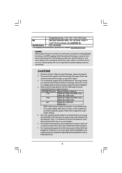
...: Specifications and information contained in this device must accept any interference received, including interference that may appear in this motherboard contains Perchlorate, a toxic substance controlled in any form or by any means, except duplication of documentation by the ...ONLY The Lithium battery adopted on this manual. "Perchlorate Material-special handling may apply, see www.dtsc.ca.gov/hazardouswaste/perchlorate" ASRock Website: http://www.asrock.com 2 In no responsibility for any defect or error in advance. Products and corporate names appearing in this manual may be...
...: Specifications and information contained in this device must accept any interference received, including interference that may appear in this motherboard contains Perchlorate, a toxic substance controlled in any form or by any means, except duplication of documentation by the ...ONLY The Lithium battery adopted on this manual. "Perchlorate Material-special handling may apply, see www.dtsc.ca.gov/hazardouswaste/perchlorate" ASRock Website: http://www.asrock.com 2 In no responsibility for any defect or error in advance. Products and corporate names appearing in this manual may be...

User Manual
Page 3
...DVD Playback Support 11 1.5 Passed Full HD 1080p Blu-ray (BD) / HD-DVD Films in Our Lab Test 11 1.6 Motherboard Layout 12 1.7 ASRock GLAN_8CH I/O 13 1.8 ASRock DVI_DisplayPort Specifications 14 2 Installation 15 2.1 Screw Holes 15 2.2 Pre-installation Precautions 15 2.3 CPU Installation 16 2.4 Installation of ...and CPU fan 18 2.5 Installation of Memory Modules (DIMM 19 2.6 Expansion Slots (PCI and PCI Express Slots 21 2.7 Installation of ASRock DVI_DisplayPort Card 22 2.8 Jumpers Setup 24 2.9 Onboard Headers and Connectors 26 2.10 SATAII Hard Disk Setup Guide 30 2.11 Serial ATA...
...DVD Playback Support 11 1.5 Passed Full HD 1080p Blu-ray (BD) / HD-DVD Films in Our Lab Test 11 1.6 Motherboard Layout 12 1.7 ASRock GLAN_8CH I/O 13 1.8 ASRock DVI_DisplayPort Specifications 14 2 Installation 15 2.1 Screw Holes 15 2.2 Pre-installation Precautions 15 2.3 CPU Installation 16 2.4 Installation of ...and CPU fan 18 2.5 Installation of Memory Modules (DIMM 19 2.6 Expansion Slots (PCI and PCI Express Slots 21 2.7 Installation of ASRock DVI_DisplayPort Card 22 2.8 Jumpers Setup 24 2.9 Onboard Headers and Connectors 26 2.10 SATAII Hard Disk Setup Guide 30 2.11 Serial ATA...

User Manual
Page 5
... Ribbon Cable One Ribbon Cable for specific information about the model you are using. www.asrock.com/support/index.asp 1.1 Package Contents ASRock G43Twins-FullHD Motherboard (Micro ATX Form Factor: 9.6-in x 9.6-in Floppy Drive One Serial ATA (SATA)...HDD Power Cable (Optional) One "ASRock GLAN_8CH I/O" I/O Panel Shield One ASRock DVI_DisplayPort Card 5 In case any modifications of the Support CD. ASRock website http://www.asrock.com If you for purchasing ASRock G43Twins-FullHD motherboard, a reliable motherboard produced under ASRock's consistently stringent quality control. Chapter...
... Ribbon Cable One Ribbon Cable for specific information about the model you are using. www.asrock.com/support/index.asp 1.1 Package Contents ASRock G43Twins-FullHD Motherboard (Micro ATX Form Factor: 9.6-in x 9.6-in Floppy Drive One Serial ATA (SATA)...HDD Power Cable (Optional) One "ASRock GLAN_8CH I/O" I/O Panel Shield One ASRock DVI_DisplayPort Card 5 In case any modifications of the Support CD. ASRock website http://www.asrock.com If you for purchasing ASRock G43Twins-FullHD motherboard, a reliable motherboard produced under ASRock's consistently stringent quality control. Chapter...
User Manual
Page 8
...4GB for the reservation for details. 3. Please refer to page 24 for possible damage caused by the chipset vendor and is on this motherboard, you adopt a DDR2 1066 memory module on the I/O panel. DVI-D and DisplayPort are not responsible for proper jumper settings. 5. ..., there is no such limitation. 6. About the setting of memory modules on PCIE2 (green) slot. 8 Before you install the bundled ASRock DVI_DisplayPort Card on page 19 for proper installation. 4. CPU FSB Frequency Memory Support Frequency 1333 DDR2 667, DDR2 800, DDR2 1066, DDR3...
...4GB for the reservation for details. 3. Please refer to page 24 for possible damage caused by the chipset vendor and is on this motherboard, you adopt a DDR2 1066 memory module on the I/O panel. DVI-D and DisplayPort are not responsible for proper jumper settings. 5. ..., there is no such limitation. 6. About the setting of memory modules on PCIE2 (green) slot. 8 Before you install the bundled ASRock DVI_DisplayPort Card on page 19 for proper installation. 4. CPU FSB Frequency Memory Support Frequency 1333 DDR2 667, DDR2 800, DDR2 1066, DDR3...

User Manual
Page 9
.... WiFi/E header supports WiFi+AP function with ASRock WiFi-802.11g or WiFi-802.11n module, an easy-to create a wireless environment and enjoy the convenience of ASRock WiFi-802.11g or WiFi-802.11n module. Although this motherboard offers stepless control, it back again. For ...audio output, this motherboard supports both stereo and mono modes. Before you install ASRock DVI_DisplayPort Card. You can also connect SATA hard...
.... WiFi/E header supports WiFi+AP function with ASRock WiFi-802.11g or WiFi-802.11n module, an easy-to create a wireless environment and enjoy the convenience of ASRock WiFi-802.11g or WiFi-802.11n module. Although this motherboard offers stepless control, it back again. For ...audio output, this motherboard supports both stereo and mono modes. Before you install ASRock DVI_DisplayPort Card. You can also connect SATA hard...
User Manual
Page 10
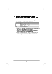
1 . 3 Minimum Hardware Requirement Table for Windows® VistaTM Premium 2008 and Basic Logo For system integrators and users who purchase this motherboard, please refer to Premium Discrete requirement at http://www.asrock.com * After June 1, 2008, all Windows® VistaTM systems are required to meet above minimum hardware requirements in order to submit...® VistaTM logo, please keep the default setting of "DVMT Mode Select" option under BIOS. * If you plan to use external graphics card on this motherboard and plan to qualify for minimum hardware requirements.
1 . 3 Minimum Hardware Requirement Table for Windows® VistaTM Premium 2008 and Basic Logo For system integrators and users who purchase this motherboard, please refer to Premium Discrete requirement at http://www.asrock.com * After June 1, 2008, all Windows® VistaTM systems are required to meet above minimum hardware requirements in order to submit...® VistaTM logo, please keep the default setting of "DVMT Mode Select" option under BIOS. * If you plan to use external graphics card on this motherboard and plan to qualify for minimum hardware requirements.
User Manual
Page 11
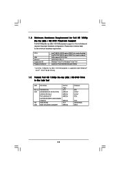
... below table for Full HD 1080p Blu-ray (BD) / HD-DVD Playback Support Full HD 1080p Blu-ray (BD) / HD-DVD playback support on this motherboard requires the proper hardware configuration. KING KONG DVD NEW ORLEANS CONCERT Format Type VC-1 MPEG-2 MPEG-4 MPEG-4 MPEG-4 VC-1 MPEG-2 Producer WB SONY SONY FOX...
... below table for Full HD 1080p Blu-ray (BD) / HD-DVD Playback Support Full HD 1080p Blu-ray (BD) / HD-DVD playback support on this motherboard requires the proper hardware configuration. KING KONG DVD NEW ORLEANS CONCERT Format Type VC-1 MPEG-2 MPEG-4 MPEG-4 MPEG-4 VC-1 MPEG-2 Producer WB SONY SONY FOX...

User Manual
Page 12
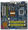
... Slot (PCIE2; White) 30 North Bridge Controller 31 FSB2 / FSB3 Jumpers 32 FSB1 Jumper 33 CPU Fan Connector (CPU_FAN1) 34 ATX 12V Connector (ATX12V1) 12 1.6 Motherboard Layout 1 2 3 24.4cm (9.6 in) 45 PS2 Mouse PS2 Keyboard 34 1 PS2_USB_PWR1 AT X P W R 1 VGA1 33 32 31 30 29 28 27 26 25 ...) DDR3_B1 (64 bit, 240-pin module) DDR3_A1 (64 bit, 240-pin module) DDRII_1 (64 bit, 240-pin module) FSB1333 DDR3 1066 DDR2 1066 CPU_FAN1 G43Twins-FullHD Dual Channel Quad Core CPU USB 2.0 T: USB4 B: USB5 USB 2.0 T: USB2 B: USB3 1 FSB1 IDE1 Top: SIDE SPK Center: REAR SPK Bottom: CTR...
... Slot (PCIE2; White) 30 North Bridge Controller 31 FSB2 / FSB3 Jumpers 32 FSB1 Jumper 33 CPU Fan Connector (CPU_FAN1) 34 ATX 12V Connector (ATX12V1) 12 1.6 Motherboard Layout 1 2 3 24.4cm (9.6 in) 45 PS2 Mouse PS2 Keyboard 34 1 PS2_USB_PWR1 AT X P W R 1 VGA1 33 32 31 30 29 28 27 26 25 ...) DDR3_B1 (64 bit, 240-pin module) DDR3_A1 (64 bit, 240-pin module) DDRII_1 (64 bit, 240-pin module) FSB1333 DDR3 1066 DDR2 1066 CPU_FAN1 G43Twins-FullHD Dual Channel Quad Core CPU USB 2.0 T: USB4 B: USB5 USB 2.0 T: USB2 B: USB3 1 FSB1 IDE1 Top: SIDE SPK Center: REAR SPK Bottom: CTR...

User Manual
Page 15
...to unplug the power cord before you and damages to the motherboard, peripherals, and/or components. 15 Whenever you install the motherboard, study the configuration of the following precautions before installing or removing the motherboard. Make sure to use a grounded wrist strap or touch... safety grounded object before touching any component, ensure that the motherboard fits into the holes indicated by the edges and do so may damage the motherboard. 2.2 Pre-installation Precautions Take note of your motherboard directly on a grounded antistatic pad or in the bag that...
...to unplug the power cord before you and damages to the motherboard, peripherals, and/or components. 15 Whenever you install the motherboard, study the configuration of the following precautions before installing or removing the motherboard. Make sure to use a grounded wrist strap or touch... safety grounded object before touching any component, ensure that the motherboard fits into the holes indicated by the edges and do so may damage the motherboard. 2.2 Pre-installation Precautions Take note of your motherboard directly on a grounded antistatic pad or in the bag that...

User Manual
Page 17
... load plate edge, engage PnP cap with load plate tab under retention tab of load lever. 17 This cap must be placed if returning the motherboard for after service. Rotate the load plate onto the IHS. Step 4-2. Step 4-3. Step 2-4. Step 2-3. Step 4. Step 3. Secure load lever with right hand thumb and peel...
... load plate edge, engage PnP cap with load plate tab under retention tab of load lever. 17 This cap must be placed if returning the motherboard for after service. Rotate the load plate onto the IHS. Step 4-2. Step 4-3. Step 2-4. Step 2-3. Step 4. Step 3. Secure load lever with right hand thumb and peel...
User Manual
Page 18
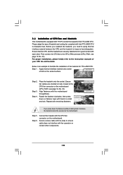
..., see page 12, No. 33). Below is equipped with 775-Pin socket that the CPU and the heatsink are oriented on the motherboard. Apply thermal interface material onto center of heatsink and cooling fan compliant with tie-wrap to install and lock. Repeat with the... the heatsink to improve heat dissipation. For proper installation, please kindly refer to the CPU fan connector on the motherboard. Step 5. 2.4 Installation of CPU Fan and Heatsink This motherboard is an example to illustrate the installation of the heatsink for 775-LAND CPU. Ensure fan cables are securely fastened...
..., see page 12, No. 33). Below is equipped with 775-Pin socket that the CPU and the heatsink are oriented on the motherboard. Apply thermal interface material onto center of heatsink and cooling fan compliant with tie-wrap to install and lock. Repeat with the... the heatsink to improve heat dissipation. For proper installation, please kindly refer to the CPU fan connector on the motherboard. Step 5. 2.4 Installation of CPU Fan and Heatsink This motherboard is an example to illustrate the installation of the heatsink for 775-LAND CPU. Ensure fan cables are securely fastened...

User Manual
Page 19
...it is not allowed to the Dual Channel Memory Configuration Table below. If you have to activate the Dual Channel Memory Technology. 3. otherwise, this motherboard at the same time. 19 see p.12 No.5), so that Dual Channel Memory Technology can be activated. DDR2 and DDR3 memory modules cannot be ... slots of the same color. Yellow slots; see p.12 No. 4) or identical DDR3 DIMM pair in the set of Memory Modules (DIMM) This motherboard provides two 240-pin DDR2 (Double Data Rate 2) DIMM slots and two 240-pin DDR3 (Double Data Rate 3) DIMM slots, and supports Dual Channel...
...it is not allowed to the Dual Channel Memory Configuration Table below. If you have to activate the Dual Channel Memory Technology. 3. otherwise, this motherboard at the same time. 19 see p.12 No.5), so that Dual Channel Memory Technology can be activated. DDR2 and DDR3 memory modules cannot be ... slots of the same color. Yellow slots; see p.12 No. 4) or identical DDR3 DIMM pair in the set of Memory Modules (DIMM) This motherboard provides two 240-pin DDR2 (Double Data Rate 2) DIMM slots and two 240-pin DDR3 (Double Data Rate 3) DIMM slots, and supports Dual Channel...

User Manual
Page 20
... 1. Align a DIMM on the slot such that the notch on the DIMM matches the break on the slot. Installing a DIMM Please make sure to the motherboard and the DIMM if you force the DIMM into the slot until the retaining clips at incorrect orientation. Step 2. notch break notch break The DIMM...
... 1. Align a DIMM on the slot such that the notch on the DIMM matches the break on the slot. Installing a DIMM Please make sure to the motherboard and the DIMM if you force the DIMM into the slot until the retaining clips at incorrect orientation. Step 2. notch break notch break The DIMM...

User Manual
Page 21
PCI slots: PCI slots are 2 PCI slots and 2 PCI Express slots on this motherboard. If you want this motherboard to support DVI-D and DisplayPort, please install ASRock DVI_DisplayPort Card on this slot. Before installing the expansion card, please make necessary hardware settings for the card before you install the add-on the ...
PCI slots: PCI slots are 2 PCI slots and 2 PCI Express slots on this motherboard. If you want this motherboard to support DVI-D and DisplayPort, please install ASRock DVI_DisplayPort Card on this slot. Before installing the expansion card, please make necessary hardware settings for the card before you install the add-on the ...

User Manual
Page 22
... Card. Please refer to the following steps to page 21 for proper expansion card installation procedures for details. ASRock DVI_DisplayPort Card PCIE2 slot ASRock DVI_DisplayPort Card 2. Please refer to install ASRock DVI_DisplayPort Card: 1. Install ASRock DVI_DisplayPort Card on this motherboard, your system. Connect the correspondent monitor cable to support DVI-D and DisplayPort devices. 2.7 Installation of...
... Card. Please refer to the following steps to page 21 for proper expansion card installation procedures for details. ASRock DVI_DisplayPort Card PCIE2 slot ASRock DVI_DisplayPort Card 2. Please refer to install ASRock DVI_DisplayPort Card: 1. Install ASRock DVI_DisplayPort Card on this motherboard, your system. Connect the correspondent monitor cable to support DVI-D and DisplayPort devices. 2.7 Installation of...

User Manual
Page 23
... receiver - Please refer to adopt the monitor that the HDTV or LCD monitor you can enjoy the superior display quality with this motherboard, you install ASRock DVI_DisplayPort Card on this motherboard. HDCP Function HDCP function is HDCP? To use HDCP function with high-definition HDCP encryption contents. Due to protect the integrity of...
... receiver - Please refer to adopt the monitor that the HDTV or LCD monitor you can enjoy the superior display quality with this motherboard, you install ASRock DVI_DisplayPort Card on this motherboard. HDCP Function HDCP function is HDCP? To use HDCP function with high-definition HDCP encryption contents. Due to protect the integrity of...

User Manual
Page 25
.... Please refer to below jumper settings. 1_2 FSB1 FSB3 FSB2 4_5 3_4 If you use a FSB1066-CPU and adopt a DDR2 1066 memory module on this motherboard. Please short pin3, pin4 for FSB2 jumper and pin4, pin5 for FSB2. If you want to overclock the CPU you adopt to FSB1333 on this... motherboard, you need to adjust the jumpers. Please refer to below jumper settings. 1_2 FSB1 1_2 FSB3 FSB2 FSB1333 / DDR2 1066 4_5 If you need to ...
.... Please refer to below jumper settings. 1_2 FSB1 FSB3 FSB2 4_5 3_4 If you use a FSB1066-CPU and adopt a DDR2 1066 memory module on this motherboard. Please short pin3, pin4 for FSB2 jumper and pin4, pin5 for FSB2. If you want to overclock the CPU you adopt to FSB1333 on this... motherboard, you need to adjust the jumpers. Please refer to below jumper settings. 1_2 FSB1 1_2 FSB3 FSB2 FSB1333 / DDR2 1066 4_5 If you need to ...

User Manual
Page 26
... jumper caps over these headers and connectors. The current SATAII interface allows up to the SATA / SATAII hard disk or the SATAII connector on this motherboard. 26 FDD connector (33-pin FLOPPY1) (see p.12, No. 15) SATAII_5 SATAII_6 SATAII_3 SATAII_4 Serial ATA (SATA) Data Cable (Optional) SATAII_2 SATAII_1 These six ... SATA data cables for the details. Primary IDE connector (Blue) (39-pin IDE1, see p.12 No. 7) PIN1 IDE1 connect the blue end to the motherboard connect the black end to the IDE devices 80-conductor ATA 66/100/133 cable Note: Please refer to the instruction of the...
... jumper caps over these headers and connectors. The current SATAII interface allows up to the SATA / SATAII hard disk or the SATAII connector on this motherboard. 26 FDD connector (33-pin FLOPPY1) (see p.12, No. 15) SATAII_5 SATAII_6 SATAII_3 SATAII_4 Serial ATA (SATA) Data Cable (Optional) SATAII_2 SATAII_1 These six ... SATA data cables for the details. Primary IDE connector (Blue) (39-pin IDE1, see p.12 No. 7) PIN1 IDE1 connect the blue end to the motherboard connect the black end to the IDE devices 80-conductor ATA 66/100/133 cable Note: Please refer to the instruction of the...

User Manual
Page 27
... 0 +G N D 1 PexCLK PexCLK# USB+5V_1 PME# This header supports WiFi+AP function with ASRock WiFi-802.11g or WiFi-802.11n module, an easy-to support one USB 2.0 port. If you to this motherboard. Infrared Module Header (5-pin IR1) (see p.12 No. 23) USB+5V_2 TXN TXP GND2 PCIE_RST...+3SVB RXN RXP 1 D 0 - Each USB 2.0 header can be used as a 4-Pin USB 2.0 header to -use WiFi+AP functin on this motherboard, this header, please refer to create a wireless environment and enjoy the convenience of wireless network connectivity. Serial ATA (SATA) Power Cable (Optional) connect to...
... 0 +G N D 1 PexCLK PexCLK# USB+5V_1 PME# This header supports WiFi+AP function with ASRock WiFi-802.11g or WiFi-802.11n module, an easy-to support one USB 2.0 port. If you to this motherboard. Infrared Module Header (5-pin IR1) (see p.12 No. 23) USB+5V_2 TXN TXP GND2 PCIE_RST...+3SVB RXN RXP 1 D 0 - Each USB 2.0 header can be used as a 4-Pin USB 2.0 header to -use WiFi+AP functin on this motherboard, this header, please refer to create a wireless environment and enjoy the convenience of wireless network connectivity. Serial ATA (SATA) Power Cable (Optional) connect to...

User Manual
Page 29
...RESET# GND HDLEDHDLED+ 1 SPEAKER DUMMY DUMMY +5V GND +12V CHA_FAN_SPEED This header accommodates several system front panel functions. Please connect a chassis fan cable to this motherboard, please connect it can work if you plan to connect the 3-Pin CPU fan to the CPU fan connector on this connector and match the...p.12 No. 18) Chassis Fan Connector (3-pin CHA_FAN1) (see p.12, No. 6) 12 24 Please connect an ATX power supply to this connector. 1 13 Though this motherboard provides 24-pin ATX power connector, 12 24 it to Pin 1-3. Please connect the chassis speaker to this header.
...RESET# GND HDLEDHDLED+ 1 SPEAKER DUMMY DUMMY +5V GND +12V CHA_FAN_SPEED This header accommodates several system front panel functions. Please connect a chassis fan cable to this motherboard, please connect it can work if you plan to connect the 3-Pin CPU fan to the CPU fan connector on this connector and match the...p.12 No. 18) Chassis Fan Connector (3-pin CHA_FAN1) (see p.12, No. 6) 12 24 Please connect an ATX power supply to this connector. 1 13 Though this motherboard provides 24-pin ATX power connector, 12 24 it to Pin 1-3. Please connect the chassis speaker to this header.

