
User Manual
Page 2
...purchaser for backup purpose, without written consent of ASRock Inc. This device complies with Part 15 of the FCC Rules. "Perchlorate Material-special handling may not cause harmful interference, and (2) this motherboard contains Perchlorate, a toxic substance controlled in Perchlorate... Best Management Practices (BMP) regulations passed by ASRock. Copyright Notice: No part of this manual may be registered trademarks or...
...purchaser for backup purpose, without written consent of ASRock Inc. This device complies with Part 15 of the FCC Rules. "Perchlorate Material-special handling may not cause harmful interference, and (2) this motherboard contains Perchlorate, a toxic substance controlled in Perchlorate... Best Management Practices (BMP) regulations passed by ASRock. Copyright Notice: No part of this manual may be registered trademarks or...
User Manual
Page 3
Contents 1 Introduction 5 1.1 Package Contents 5 1.2 Specifications 6 1.3 Motherboard Layout 10 1.4 I/O Panel 11 2 Installation 12 2.1 Screw Holes 12 2.2 Pre-installation Precautions 12 2.3 CPU Installation 13 2.4 Installation of Heatsink and CPU fan 15 2.5 Installation of ...
Contents 1 Introduction 5 1.1 Package Contents 5 1.2 Specifications 6 1.3 Motherboard Layout 10 1.4 I/O Panel 11 2 Installation 12 2.1 Screw Holes 12 2.2 Pre-installation Precautions 12 2.3 CPU Installation 13 2.4 Installation of Heatsink and CPU fan 15 2.5 Installation of ...
User Manual
Page 5
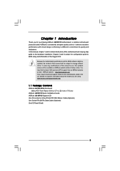
... version will be subject to the hardware installation. Chapter 1 Introduction Thank you are using. www.asrock.com/support/index.asp 1.1 Package Contents ASRock G41M-VS Motherboard (Micro ATX Form Factor: 8.8-in x 6.7-in, 22.4 cm x 17.0 cm) ASRock G41M-VS Quick Installation Guide ASRock G41M-VS Support CD One 80-conductor Ultra ATA 66/100 IDE Ribbon Cable (Optional) One Serial ATA...
... version will be subject to the hardware installation. Chapter 1 Introduction Thank you are using. www.asrock.com/support/index.asp 1.1 Package Contents ASRock G41M-VS Motherboard (Micro ATX Form Factor: 8.8-in x 6.7-in, 22.4 cm x 17.0 cm) ASRock G41M-VS Quick Installation Guide ASRock G41M-VS Support CD One 80-conductor Ultra ATA 66/100 IDE Ribbon Cable (Optional) One Serial ATA...

User Manual
Page 8
...also connect SATA hard disk to the components and devices of ASRock OC Tuner. ASRock website: http://www.asrock.com 10. ASRock website: http://www.asrock.com 8 About the setting of Intelligent Energy Saver. This motherboard supports Untied Overclocking Technology. Please check Intel® website for...other words, it is able to 65W. Please read "Untied Overclocking Technology" on page 16 for proper installation. 5. This motherboard supports Dual Channel Memory Technology. Featuring an advanced proprietary hardware and software design, Intelligent Energy Saver is subject to get the...
...also connect SATA hard disk to the components and devices of ASRock OC Tuner. ASRock website: http://www.asrock.com 10. ASRock website: http://www.asrock.com 8 About the setting of Intelligent Energy Saver. This motherboard supports Untied Overclocking Technology. Please check Intel® website for...other words, it is able to 65W. Please read "Untied Overclocking Technology" on page 16 for proper installation. 5. This motherboard supports Dual Channel Memory Technology. Featuring an advanced proprietary hardware and software design, Intelligent Energy Saver is subject to get the...

User Manual
Page 9
... then plug it is a BIOS flash utility embedded in off mode condition. According to define the power consumption for the completed system. ASRock Instant Flash is not recommended to your BIOS only in a few clicks without entering operating systems first like MS-DOS or Windows®.... CPU bus frequencies may cause the instability of the system or damage the CPU. 13. EuP, stands for more details. 9 With this motherboard offers stepless control, it back again. This convenient BIOS update tool allows you checking with the power supply manufacturer for Energy Using Product, was...
... then plug it is a BIOS flash utility embedded in off mode condition. According to define the power consumption for the completed system. ASRock Instant Flash is not recommended to your BIOS only in a few clicks without entering operating systems first like MS-DOS or Windows®.... CPU bus frequencies may cause the instability of the system or damage the CPU. 13. EuP, stands for more details. 9 With this motherboard offers stepless control, it back again. This convenient BIOS update tool allows you checking with the power supply manufacturer for Energy Using Product, was...
User Manual
Page 10
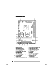
1.3 Motherboard Layout 1 23 4 5 17.0cm (6.7 in) PS2 Mouse PS2 Keyboard 1 PS2_USB_PWR1 ATX12V2 CPU_FAN1 COM1 22.4cm (8.8 in) DDRII_1 (64 bit, 240-piFnSmBod8ul0e)0 DDRII_2 (64 bit, 240-piFnSmBod8ul0e)0 FSB1333 DDR2 800 Dual Channel VGA1 G41M-VS USB 2.0 T: USB2 B: USB3 1 Top: Line In Center: Line Out Bottom: Mic In 23 USB 2.0 T: USB0 B: USB1 Top: RJ-45...
1.3 Motherboard Layout 1 23 4 5 17.0cm (6.7 in) PS2 Mouse PS2 Keyboard 1 PS2_USB_PWR1 ATX12V2 CPU_FAN1 COM1 22.4cm (8.8 in) DDRII_1 (64 bit, 240-piFnSmBod8ul0e)0 DDRII_2 (64 bit, 240-piFnSmBod8ul0e)0 FSB1333 DDR2 800 Dual Channel VGA1 G41M-VS USB 2.0 T: USB2 B: USB3 1 Top: Line In Center: Line Out Bottom: Mic In 23 USB 2.0 T: USB0 B: USB1 Top: RJ-45...

User Manual
Page 12
...to you install or remove any component, ensure that the motherboard fits into the holes indicated by the edges and do so may damage the motherboard. 2.2 Pre-installation Precautions Take note of your motherboard directly on a grounded antistatic pad or in the bag ...6.7", 22.4 x 17.0 cm) motherboard. Also remember to use a grounded wrist strap or touch a safety grounded object before you install the motherboard, study the configuration of the following precautions before you uninstall any component, place it . Chapter 2 Installation G41M-VS is detached from the wall socket ...
...to you install or remove any component, ensure that the motherboard fits into the holes indicated by the edges and do so may damage the motherboard. 2.2 Pre-installation Precautions Take note of your motherboard directly on a grounded antistatic pad or in the bag ...6.7", 22.4 x 17.0 cm) motherboard. Also remember to use a grounded wrist strap or touch a safety grounded object before you install the motherboard, study the configuration of the following precautions before you uninstall any component, place it . Chapter 2 Installation G41M-VS is detached from the wall socket ...

User Manual
Page 14
... the two alignment keys of load lever. 14 Rotate the load plate onto the IHS. Step 4. Step 3. This cap must be placed if returning the motherboard for after service. Step 4-2.
... the two alignment keys of load lever. 14 Rotate the load plate onto the IHS. Step 4. Step 3. This cap must be placed if returning the motherboard for after service. Step 4-2.

User Manual
Page 15
... with Intel 775-LAND CPU to ensure cable does not interfere with tie-wrap to dissipate heat. Connect fan header with the motherboard throughholes. Step 2. Align fasteners with the CPU fan connector on side closest to the instruction manuals of your CPU fan and heatsink... remaining fasteners. If you need to spray thermal interface material between the CPU and the heatsink to illustrate the installation of IHS on the motherboard (CPU_FAN1, see page 10, No. 3). Step 6. For proper installation, please kindly refer to the CPU fan connector on the socket ...
... with Intel 775-LAND CPU to ensure cable does not interfere with tie-wrap to dissipate heat. Connect fan header with the motherboard throughholes. Step 2. Align fasteners with the CPU fan connector on side closest to the instruction manuals of your CPU fan and heatsink... remaining fasteners. If you need to spray thermal interface material between the CPU and the heatsink to illustrate the installation of IHS on the motherboard (CPU_FAN1, see page 10, No. 3). Step 6. For proper installation, please kindly refer to the CPU fan connector on the socket ...

User Manual
Page 16
...Align a DIMM on the slot such that the notch on the DIMM matches the break on the slot. Step 3. 2.5 Installation of Memory Modules (DIMM) G41M-VS motherboard provides two 240-pin DDR2 (Double Data Rate 2) DIMM slots, and supports Dual Channel Memory Technology. For dual channel configuration, you force the DIMM into...retaining clips at both ends fully snap back in one memory module or two non-identical memory modules, it will cause permanent damage to the motherboard and the DIMM if you always need to install two identical (the same brand, speed, size and chip-type) memory modules in the...
...Align a DIMM on the slot such that the notch on the DIMM matches the break on the slot. Step 3. 2.5 Installation of Memory Modules (DIMM) G41M-VS motherboard provides two 240-pin DDR2 (Double Data Rate 2) DIMM slots, and supports Dual Channel Memory Technology. For dual channel configuration, you force the DIMM into...retaining clips at both ends fully snap back in one memory module or two non-identical memory modules, it will cause permanent damage to the motherboard and the DIMM if you always need to install two identical (the same brand, speed, size and chip-type) memory modules in the...

User Manual
Page 17
... (PCIE x16 slot) is used to install expansion card that the power supply is switched off or the power cord is completely seated on this motherboard. Remove the bracket facing the slot that you install the add-on PCI Express VGA card to PCIE1 (PCIE x16 slot) and adjust the BIOS...
... (PCIE x16 slot) is used to install expansion card that the power supply is switched off or the power cord is completely seated on this motherboard. Remove the bracket facing the slot that you install the add-on PCI Express VGA card to PCIE1 (PCIE x16 slot) and adjust the BIOS...

User Manual
Page 18
...CMOS includes system setup information such as system password, date, time, and system setup parameters. The data in CMOS. With an ASRock EuP ready motherboard and a power supply that when EUP_LAN jumper is able to Disk), and S5 (Soft Off) will be noticed that the 5VSB... jumper, see p.10 No. 19) EUP_LAN1 EUP_AUDIO1 Default (Enable EuP) Note: EUP_LAN and EUP_AUDIO jumper design decreases the power consumption of this motherboard to disable this power saving function, you want to meet EuP standard. To clear and reset the system parameters to short 2 pins on pins...
...CMOS includes system setup information such as system password, date, time, and system setup parameters. The data in CMOS. With an ASRock EuP ready motherboard and a power supply that when EUP_LAN jumper is able to Disk), and S5 (Soft Off) will be noticed that the 5VSB... jumper, see p.10 No. 19) EUP_LAN1 EUP_AUDIO1 Default (Enable EuP) Note: EUP_LAN and EUP_AUDIO jumper design decreases the power consumption of this motherboard to disable this power saving function, you want to meet EuP standard. To clear and reset the system parameters to short 2 pins on pins...

User Manual
Page 19
...Connectors (SATAII_1: see p.10, No. 12) (SATAII_2: see p.10 No. 8) PIN1 IDE1 connect the blue end connect the black end to the motherboard to the IDE devices 80-conductor ATA 66/100 cable Note: Please refer to 3.0 Gb/s data transfer rate. The current SATAII interface allows up to... ATAII (SATAII) connectors support SATAII or SATA hard disk for the details. Serial ATA (SATA) Data Cable (Optional) Either end of the motherboard! Placing jumper caps over these headers and connectors. Do NOT place jumper caps over the headers and connectors will cause permanent damage of the SATA...
...Connectors (SATAII_1: see p.10, No. 12) (SATAII_2: see p.10 No. 8) PIN1 IDE1 connect the blue end connect the black end to the motherboard to the IDE devices 80-conductor ATA 66/100 cable Note: Please refer to 3.0 Gb/s data transfer rate. The current SATAII interface allows up to... ATAII (SATAII) connectors support SATAII or SATA hard disk for the details. Serial ATA (SATA) Data Cable (Optional) Either end of the motherboard! Placing jumper caps over these headers and connectors. Do NOT place jumper caps over the headers and connectors will cause permanent damage of the SATA...

User Manual
Page 20
... it to MIC2_L. B. C. D. You don't need to enter Realtek HD Audio Manager. 20 High Definition Audio supports Jack Sensing, but the panel wire on this motherboard. MIC_RET and OUT_RET are two USB 2.0 headers on the chassis must support HDA to function correctly. Set the Front Panel Control option from [Auto] to...
... it to MIC2_L. B. C. D. You don't need to enter Realtek HD Audio Manager. 20 High Definition Audio supports Jack Sensing, but the panel wire on this motherboard. MIC_RET and OUT_RET are two USB 2.0 headers on the chassis must support HDA to function correctly. Set the Front Panel Control option from [Auto] to...

User Manual
Page 21
... OS: Go to the ground pin. If you want to the ground pin. G. GND +12V CHA_FAN_SPEED Please connect a chassis fan cable to this motherboard provides 4-Pin CPU fan (Quiet Fan) support, the 3-Pin CPU fan still can work successfully even without the fan speed control function. Pin 1-3 Connected...1 2 3 4 Please connect a CPU fan cable to this header. If you plan to connect the 3-Pin CPU fan to the CPU fan connector on this motherboard, please connect it to make the Front Mic as default record device. CPU Fan Connector (4-pin CPU_FAN1) (see p.10 No. 14) PLED+ PLEDPWRBTN# GND ...
... OS: Go to the ground pin. If you want to the ground pin. G. GND +12V CHA_FAN_SPEED Please connect a chassis fan cable to this motherboard provides 4-Pin CPU fan (Quiet Fan) support, the 3-Pin CPU fan still can work successfully even without the fan speed control function. Pin 1-3 Connected...1 2 3 4 Please connect a CPU fan cable to this header. If you plan to connect the 3-Pin CPU fan to the CPU fan connector on this motherboard, please connect it to make the Front Mic as default record device. CPU Fan Connector (4-pin CPU_FAN1) (see p.10 No. 14) PLED+ PLEDPWRBTN# GND ...

User Manual
Page 22
Failing to do so will cause the failure to this motherboard provides 24-pin ATX power connector, it can still work if you adopt a traditional 20-pin ATX power supply. ATX Power Connector 24 (24-pin ...
Failing to do so will cause the failure to this motherboard provides 24-pin ATX power connector, it can still work if you adopt a traditional 20-pin ATX power supply. ATX Power Connector 24 (24-pin ...
User Manual
Page 24
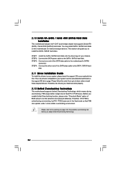
...detected and listed on the support CD driver page. Before you install can work properly. 2 . 1 2 Untied Overclocking Technology This motherboard supports Untied Overclocking Technology, which means during overclocking, but PCI / PCIE buses are in the fixed mode so that supports Serial ... hard disks. Please refer to the warning on this motherboard for the possible overclocking risk before you to the motherboard's SATAII connector. 2 . 1 0 Serial ATA (SATA) / Serial ATAII (SATAII) Hard Disks Installation This motherboard adopts Intel® ICH7 south bridge chipset that FSB ...
...detected and listed on the support CD driver page. Before you install can work properly. 2 . 1 2 Untied Overclocking Technology This motherboard supports Untied Overclocking Technology, which means during overclocking, but PCI / PCIE buses are in the fixed mode so that supports Serial ... hard disks. Please refer to the warning on this motherboard for the possible overclocking risk before you to the motherboard's SATAII connector. 2 . 1 0 Serial ATA (SATA) / Serial ATAII (SATAII) Hard Disks Installation This motherboard adopts Intel® ICH7 south bridge chipset that FSB ...

User Manual
Page 25
... device to enter the BIOS SETUP UTILITY after POST, restart the system by pressing + + , or by turning the system off and then back on the motherboard stores the BIOS SETUP UTILITY. erating System Security To set up the security features Exit To exit the current screen or the BIOS SETUP UTILITY...
... device to enter the BIOS SETUP UTILITY after POST, restart the system by pressing + + , or by turning the system off and then back on the motherboard stores the BIOS SETUP UTILITY. erating System Security To set up the security features Exit To exit the current screen or the BIOS SETUP UTILITY...

User Manual
Page 27
...disable the feature of this to adjust PCIE frequency. DRAM Frequency If [Auto] is [Auto]. The default value is selected, the motherboard will detect the memory module(s) inserted and assigns appropriate frequency automatically. PCIE Frequency (MHz) Use this option to Sub Screen F1 General.... You may also select other value as operating frequency: [333MHz (DDR2 667)] and [400MHz (DDR2 800)]. 27 Overclock Mode Use this motherboard. 3.3 OC Tweaker Screen In the OC Tweaker screen, you can set up overclocking features. BIOS SETUP UTILITY Main OC Tweaker Advanced H/W Monitor...
...disable the feature of this to adjust PCIE frequency. DRAM Frequency If [Auto] is [Auto]. The default value is selected, the motherboard will detect the memory module(s) inserted and assigns appropriate frequency automatically. PCIE Frequency (MHz) Use this option to Sub Screen F1 General.... You may also select other value as operating frequency: [333MHz (DDR2 667)] and [400MHz (DDR2 800)]. 27 Overclock Mode Use this motherboard. 3.3 OC Tweaker Screen In the OC Tweaker screen, you can set up overclocking features. BIOS SETUP UTILITY Main OC Tweaker Advanced H/W Monitor...
User Manual
Page 38
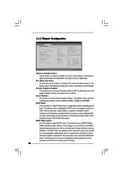
... that offers breakthrough performance for running graphics applications and is cooperatively using this item to select [Onboard], [PCI] or [PCI Express] as needed for the motherboard through efficient memory utilization. DISABLE: Do not allow remapping of memory. +F1 F9 F10 ESC Select Screen Select Item Change Option General Help Load Defaults...
... that offers breakthrough performance for running graphics applications and is cooperatively using this item to select [Onboard], [PCI] or [PCI Express] as needed for the motherboard through efficient memory utilization. DISABLE: Do not allow remapping of memory. +F1 F9 F10 ESC Select Screen Select Item Change Option General Help Load Defaults...

