User Manual
Page 3
...(SATA) / Serial ATAII (SATAII) Hard Disks Installation 25 2.11 Driver Installation Guide 25 2.12 Untied Overclocking Technology 25 3 BIOS SETUP UTILITY 26 3.1 Introduction 26 3.1.1 BIOS Menu Bar 26 3.1.2 Navigation Keys 27 3.2 Main Screen 27 3.3 OC Tweaker Screen 28 3.4 Advanced Screen 31 3.4.1 CPU Configuration 32 3.4.2 Chipset Configuration 34 3.4.3 ACPI Configuration 40 3.4.4 Storage Configuration 41 3.4.5 PCIPnP Configuration 43 3.4.6 Floppy Configuration 44 3.4.7 Super IO Configuration 44 3.4.8 USB Configuration 45 3.5 Hardware Health Event Monitoring Screen 46 3.6 Boot...
...(SATA) / Serial ATAII (SATAII) Hard Disks Installation 25 2.11 Driver Installation Guide 25 2.12 Untied Overclocking Technology 25 3 BIOS SETUP UTILITY 26 3.1 Introduction 26 3.1.1 BIOS Menu Bar 26 3.1.2 Navigation Keys 27 3.2 Main Screen 27 3.3 OC Tweaker Screen 28 3.4 Advanced Screen 31 3.4.1 CPU Configuration 32 3.4.2 Chipset Configuration 34 3.4.3 ACPI Configuration 40 3.4.4 Storage Configuration 41 3.4.5 PCIPnP Configuration 43 3.4.6 Floppy Configuration 44 3.4.7 Super IO Configuration 44 3.4.8 USB Configuration 45 3.5 Hardware Health Event Monitoring Screen 46 3.6 Boot...
User Manual
Page 7
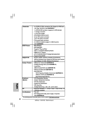
...Temperature Sensing Monitor - Microsoft® Windows® 7 / 7 64-bit / VistaTM / VistaTM 64-bit / XP / XP 64-bit compliant Certifications - FCC, CE - Front panel audio connector - 2 x USB 2.0 headers (support 4 USB 2.0 ports) (see CAUTION 14) - Supports Smart BIOS Support CD - Hybrid Booster: - Voltage Monitoring: +12V, +5V, +3.3V, Vcore OS - Intelligent Energy Saver (see CAUTION 15) - Instant Boot - ASRock U-COP (see CAUTION 11) - Chassis Temperature Sensing - CPU Fan Tachometer - Chassis Fan Tachometer - EuP Ready (EuP ready power supply...
...Temperature Sensing Monitor - Microsoft® Windows® 7 / 7 64-bit / VistaTM / VistaTM 64-bit / XP / XP 64-bit compliant Certifications - FCC, CE - Front panel audio connector - 2 x USB 2.0 headers (support 4 USB 2.0 ports) (see CAUTION 14) - Supports Smart BIOS Support CD - Hybrid Booster: - Voltage Monitoring: +12V, +5V, +3.3V, Vcore OS - Intelligent Energy Saver (see CAUTION 15) - Instant Boot - ASRock U-COP (see CAUTION 11) - Chassis Temperature Sensing - CPU Fan Tachometer - Chassis Fan Tachometer - EuP Ready (EuP ready power supply...
User Manual
Page 9
... and worked on the motherboard functions properly and unplug the power cord, then plug it is higher than the recommended CPU bus frequencies may cause the instability of overclocking settings. It helps you to save the new BIOS file to spray thermal grease between the CPU and the heatsink when you what it back again. To improve heat dissipation, remember to your USB flash drive, floppy disk or hard drive...
... and worked on the motherboard functions properly and unplug the power cord, then plug it is higher than the recommended CPU bus frequencies may cause the instability of overclocking settings. It helps you to save the new BIOS file to spray thermal grease between the CPU and the heatsink when you what it back again. To improve heat dissipation, remember to your USB flash drive, floppy disk or hard drive...
User Manual
Page 10
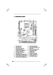
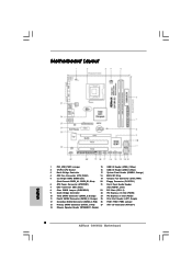
... (SATAII_4; Red) 27 ATX 12V Connector (ATX12V1) 14 Chassis Speaker Header (SPEAKER 1, Purple) 10 Blue) 20 Floppy Connector (FLOPPY1) 6 ATX Power Connector (ATXPWR1) 21 Front Panel Audio Header 7 IDE1 Connector (IDE1, Blue) (HD_AUDIO1, Lime) 8 Clear CMOS Jumper (CLRCMOS1) 22 PCI Slots (PCI1- 2) 9 South Bridge Controller 23 PCI Express x16 Slot (PCIE2) 10 Third SATAII Connector (SATAII_3; 1.3 Motherboard Layout 1 2 34 5 19.3cm (7.6 in) 1 PS2_USB_PWR1 CPU_FAN1 PS2 Mouse PS2 Keyboard DDR3 1333 Dual Channel COM1 FSB1333 DDR3_A1 (64 bit, 240-FpinSBmo8d0ul0e) DDR3_B1...
... (SATAII_4; Red) 27 ATX 12V Connector (ATX12V1) 14 Chassis Speaker Header (SPEAKER 1, Purple) 10 Blue) 20 Floppy Connector (FLOPPY1) 6 ATX Power Connector (ATXPWR1) 21 Front Panel Audio Header 7 IDE1 Connector (IDE1, Blue) (HD_AUDIO1, Lime) 8 Clear CMOS Jumper (CLRCMOS1) 22 PCI Slots (PCI1- 2) 9 South Bridge Controller 23 PCI Express x16 Slot (PCIE2) 10 Third SATAII Connector (SATAII_3; 1.3 Motherboard Layout 1 2 34 5 19.3cm (7.6 in) 1 PS2_USB_PWR1 CPU_FAN1 PS2 Mouse PS2 Keyboard DDR3 1333 Dual Channel COM1 FSB1333 DDR3_A1 (64 bit, 240-FpinSBmo8d0ul0e) DDR3_B1...
User Manual
Page 21
... 64-bit OS: Click "Audio I /O panel, there are for HD audio panel only. If you use AC'97 audio panel, please install it to [Enabled]. Connect Audio_R (RIN) to OUT2_R and Audio_L (LIN) to Ground (GND). Connect Ground (GND) to OUT2_L. D. Enter Advanced Settings, and then select Chipset Configuration. F. Please follow the instruction in our manual and chassis manual to MIC2_L. Connect Mic_IN (MIC) to install your system. 2. C. E. Each USB 2.0 header can support two USB 2.0 ports. 1 GND...
... 64-bit OS: Click "Audio I /O panel, there are for HD audio panel only. If you use AC'97 audio panel, please install it to [Enabled]. Connect Audio_R (RIN) to OUT2_R and Audio_L (LIN) to Ground (GND). Connect Ground (GND) to OUT2_L. D. Enter Advanced Settings, and then select Chipset Configuration. F. Please follow the instruction in our manual and chassis manual to MIC2_L. Connect Mic_IN (MIC) to install your system. 2. C. E. Each USB 2.0 header can support two USB 2.0 ports. 1 GND...
User Manual
Page 25
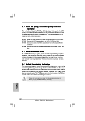
... due to install the SATA / SATAII hard disks. STEP 2: Connect the SATA power cable to the warning on page 8 for internal storage devices. You may install SATA / SATAII hard disks on the support CD driver page. Then, the drivers compatible to your system can be auto-detected and listed on this motherboard for the possible overclocking risk before you enable Untied Overclocking function, please enter "Overclock Mode" option of the SATA data cable to the SATA / SATAII hard disk. 2.11 Driver Installation Guide To install the drivers to your...
... due to install the SATA / SATAII hard disks. STEP 2: Connect the SATA power cable to the warning on page 8 for internal storage devices. You may install SATA / SATAII hard disks on the support CD driver page. Then, the drivers compatible to your system can be auto-detected and listed on this motherboard for the possible overclocking risk before you enable Untied Overclocking function, please enter "Overclock Mode" option of the SATA data cable to the SATA / SATAII hard disk. 2.11 Driver Installation Guide To install the drivers to your...
User Manual
Page 30
.... is [Auto]. The default value is Intel's new power saving technology. This item will find this motherboard. Please set the "Power Schemes" as "Portable/Laptop" to adjust CPU frequency. Cnfiguration options: [Auto], [Manual] and [Optimized]. NB Voltage Use this to adjust PCIE frequency. in advance. Overclock Mode Use this to [Disable] if above issue occurs. PCIE Frequency (MHz) Use this to [2.40V]. DRAM Voltage Use this option to select Overclock Mode. Configuration options: [Auto], [1.48V] to select DRAM Voltage. If the CPU you adopt supports EIST...
.... is [Auto]. The default value is Intel's new power saving technology. This item will find this motherboard. Please set the "Power Schemes" as "Portable/Laptop" to adjust CPU frequency. Cnfiguration options: [Auto], [Manual] and [Optimized]. NB Voltage Use this to adjust PCIE frequency. in advance. Overclock Mode Use this to [Disable] if above issue occurs. PCIE Frequency (MHz) Use this to [2.40V]. DRAM Voltage Use this option to select Overclock Mode. Configuration options: [Auto], [1.48V] to select DRAM Voltage. If the CPU you adopt supports EIST...

User Manual
Page 32
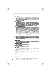
... This is a read-only item, which displays whether the ratio status of this motherboard. Overclock Mode Use this motherboard is unlocked, you will find this option to adjust PCIE frequency. In the C1 power state, the processor maintains the context of Boot Failure Guard. 3.4.1 CPU Configuration BIOS SETUP UTILITY Advanced CPU Configuration Overclock Mode CPU Frequency (MHz) PCIE Frequency (MHz) Boot Failure Guard Spread Spectrum [Auto] [200] [100] [Enabled] [Auto] Ratio Status Ratio CMOS Setting Unlocked (Min:06, Max:17) 17 [17] Enhanced Halt...
... This is a read-only item, which displays whether the ratio status of this motherboard. Overclock Mode Use this motherboard is unlocked, you will find this option to adjust PCIE frequency. In the C1 power state, the processor maintains the context of Boot Failure Guard. 3.4.1 CPU Configuration BIOS SETUP UTILITY Advanced CPU Configuration Overclock Mode CPU Frequency (MHz) PCIE Frequency (MHz) Boot Failure Guard Spread Spectrum [Auto] [200] [100] [Enabled] [Auto] Ratio Status Ratio CMOS Setting Unlocked (Min:06, Max:17) 17 [17] Enhanced Halt...
User Manual
Page 33
...% slacking off interval ratio. The default value is set this item to system stability or compatibility issue with "No Execute (NX) Memory Protection" can prevent data pages from overheated. is Intel's new power saving technology. Processor can utilize the additional hardware capabilities provided by malicious software to [Enabled] if using Microsoft® Windows® XP, or Linux kernel version 2.4.18 or higher. Configuration options: [Auto], [Enabled] and [Disabled].
...% slacking off interval ratio. The default value is set this item to system stability or compatibility issue with "No Execute (NX) Memory Protection" can prevent data pages from overheated. is Intel's new power saving technology. Processor can utilize the additional hardware capabilities provided by malicious software to [Enabled] if using Microsoft® Windows® XP, or Linux kernel version 2.4.18 or higher. Configuration options: [Auto], [Enabled] and [Disabled].
User Manual
Page 38
... because the driver will be disabled when PCI Sound Card is cooperatively using this item if you adopt the memory module with other system components. DVMT/FIXED Memory You are allowed to adjust the shared memory size in Intel® 4 Series Express chipset family to enable this option to set DVMT Mode Select as needed for the motherboard through efficient memory utilization. Onboard HD Audio Select [Auto], [Enabled] or [Disabled] for the onboard HD Audio Front Panel. 38
... because the driver will be disabled when PCI Sound Card is cooperatively using this item if you adopt the memory module with other system components. DVMT/FIXED Memory You are allowed to adjust the shared memory size in Intel® 4 Series Express chipset family to enable this option to set DVMT Mode Select as needed for the motherboard through efficient memory utilization. Onboard HD Audio Select [Auto], [Enabled] or [Disabled] for the onboard HD Audio Front Panel. 38
User Manual
Page 43
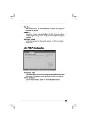
... Select Screen Select Item Change Option General Help Load Defaults Save and Exit Exit v02.54 (C) Copyright 1985-2005, American Megatrends, Inc. Configuration options: [Disabled], [Auto], [Enabled]. 32-Bit Data Transfer Use this item to maximize the IDE hard disk data transfer rate. 3.4.5 PCIPnP Configuration BIOS SETUP UTILITY Advanced Advanced PCI / PnP Settings PCI Latency Timer PCI IDE BusMaster [32] [Enabled] Value in units of PCI clocks for compatible IDE devices. S.M.A.R.T. Use this item to enable 32-bit access to enable or disable the S.M.A.R.T. (Self-Monitoring, Analysis...
... Select Screen Select Item Change Option General Help Load Defaults Save and Exit Exit v02.54 (C) Copyright 1985-2005, American Megatrends, Inc. Configuration options: [Disabled], [Auto], [Enabled]. 32-Bit Data Transfer Use this item to maximize the IDE hard disk data transfer rate. 3.4.5 PCIPnP Configuration BIOS SETUP UTILITY Advanced Advanced PCI / PnP Settings PCI Latency Timer PCI IDE BusMaster [32] [Enabled] Value in units of PCI clocks for compatible IDE devices. S.M.A.R.T. Use this item to enable 32-bit access to enable or disable the S.M.A.R.T. (Self-Monitoring, Analysis...
User Manual
Page 45
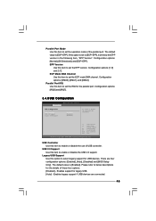
...: [DMA0], [DMA1], and [DMA3]. Configuration options: [IRQ5] and [IRQ7]. 3.4.8 USB Configuration BIOS SETUP UTILITY Advanced USB Configuration USB Controller USB 2.0 Support Legacy USB Support [Enabled] [Enabled] [Enabled] To enable or disable the onboard USB controllers. +F1 F9 F10 ESC Select Screen Select Item Change Option General Help Load Defaults Save and Exit Exit v02.54 (C) Copyright 1985-2005, American Megatrends, Inc. If this option is set the EPP version. There are connected. 45 The default value is [ECP+EPP]. Parallel Port Mode Use this item to [ECP...
...: [DMA0], [DMA1], and [DMA3]. Configuration options: [IRQ5] and [IRQ7]. 3.4.8 USB Configuration BIOS SETUP UTILITY Advanced USB Configuration USB Controller USB 2.0 Support Legacy USB Support [Enabled] [Enabled] [Enabled] To enable or disable the onboard USB controllers. +F1 F9 F10 ESC Select Screen Select Item Change Option General Help Load Defaults Save and Exit Exit v02.54 (C) Copyright 1985-2005, American Megatrends, Inc. If this option is set the EPP version. There are connected. 45 The default value is [ECP+EPP]. Parallel Port Mode Use this item to [ECP...
User Manual
Page 48
... Enter Change F1 General Help F9 Load Defaults F10 Save and Exit ESC Exit v02.54 (C) Copyright 1985-2005, American Megatrends, Inc. 48 For the user password, you may also clear it will automatically activate the Numeric Lock function after boot-up. 3.7 Security Screen In this item to enable or disable the Boot From Onboard LAN feature. BIOS SETUP UTILITY Main OC Tweaker Advanced H/W Monitor Boot Security Exit Security Settings Supervisor Password...
... Enter Change F1 General Help F9 Load Defaults F10 Save and Exit ESC Exit v02.54 (C) Copyright 1985-2005, American Megatrends, Inc. 48 For the user password, you may also clear it will automatically activate the Numeric Lock function after boot-up. 3.7 Security Screen In this item to enable or disable the Boot From Onboard LAN feature. BIOS SETUP UTILITY Main OC Tweaker Advanced H/W Monitor Boot Security Exit Security Settings Supervisor Password...
User Manual
Page 50
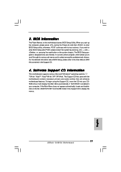
... the motherboard contains necessary drivers and useful utilities that the motherboard supports. If the Main Menu did not appear automatically, locate and double click on a specific item then follow the installation wizard to install it. 4.2.4 Contact Information If you may contact your OS documentation for more about ASRock, welcome to display the menus. 4.2.2 Drivers Menu The Drivers Menu shows the available devices drivers if the system detects installed devices. Click on the file...
... the motherboard contains necessary drivers and useful utilities that the motherboard supports. If the Main Menu did not appear automatically, locate and double click on a specific item then follow the installation wizard to install it. 4.2.4 Contact Information If you may contact your OS documentation for more about ASRock, welcome to display the menus. 4.2.2 Drivers Menu The Drivers Menu shows the available devices drivers if the system detects installed devices. Click on the file...
Quick Installation Guide
Page 2
...Port Header (LPT1, Purple) 12 Secondary SATAII Connector (SATAII_2; Blue) 20 Floppy Connector (FLOPPY1) 6 ATX Power Connector (ATXPWR1) 21 Front Panel Audio Header 7 IDE1 Connector (IDE1, Blue) (HD_AUDIO1, Lime) 8 Clear CMOS Jumper (CLRCMOS1) 22 PCI Slots (PCI1- 2) 9 South Bridge Controller 23 PCI Express x16 Slot (PCIE2) 10 Third SATAII Connector (SATAII_3; Red) 27 ATX 12V Connector (ATX12V1) 14 Chassis Speaker Header (SPEAKER 1, Purple) 2 ASRock G41M-S3 Motherboard Motherboard Layout English 1 PS2_USB_PWR1 Jumper 15 USB 2.0 Header (USB6_7, Blue) 2 775-Pin CPU Socket...
...Port Header (LPT1, Purple) 12 Secondary SATAII Connector (SATAII_2; Blue) 20 Floppy Connector (FLOPPY1) 6 ATX Power Connector (ATXPWR1) 21 Front Panel Audio Header 7 IDE1 Connector (IDE1, Blue) (HD_AUDIO1, Lime) 8 Clear CMOS Jumper (CLRCMOS1) 22 PCI Slots (PCI1- 2) 9 South Bridge Controller 23 PCI Express x16 Slot (PCIE2) 10 Third SATAII Connector (SATAII_3; Red) 27 ATX 12V Connector (ATX12V1) 14 Chassis Speaker Header (SPEAKER 1, Purple) 2 ASRock G41M-S3 Motherboard Motherboard Layout English 1 PS2_USB_PWR1 Jumper 15 USB 2.0 Header (USB6_7, Blue) 2 775-Pin CPU Socket...
Quick Installation Guide
Page 6
...: - CPU Fan Tachometer - CPU/Chassis FAN connector - 24 pin ATX power connector - 4 pin 12V power connector - Front panel audio connector - 2 x USB 2.0 headers (support 4 USB 2.0 ports) (see CAUTION 14) - ACPI 1.1 Compliance Wake Up Events - AMBIOS 2.3.1 Support - CPU, VCCM, NB, SB,VTT Voltage Multi-adjustment - Drivers, Utilities, AntiVirus Software (Trial Version), ASRock Software Suite (CyberLink DVD Suite and Creative Sound Blaster X-Fi MB) (OEM and Trial Version) Unique Feature - CPU Frequency Stepless Control (see CAUTION 9) BIOS Feature - 8Mb AMI BIOS...
...: - CPU Fan Tachometer - CPU/Chassis FAN connector - 24 pin ATX power connector - 4 pin 12V power connector - Front panel audio connector - 2 x USB 2.0 headers (support 4 USB 2.0 ports) (see CAUTION 14) - ACPI 1.1 Compliance Wake Up Events - AMBIOS 2.3.1 Support - CPU, VCCM, NB, SB,VTT Voltage Multi-adjustment - Drivers, Utilities, AntiVirus Software (Trial Version), ASRock Software Suite (CyberLink DVD Suite and Creative Sound Blaster X-Fi MB) (OEM and Trial Version) Unique Feature - CPU Frequency Stepless Control (see CAUTION 9) BIOS Feature - 8Mb AMI BIOS...
Quick Installation Guide
Page 7
... even cause damage to the components and devices of "User Manual" in overclocking mode. * When you use a FSB533-CPU on this motherboard, it will operate in the support CD to adjust your SATAII hard disk drive to SATAII connector, please read the "SATAII Hard Disk Setup Guide" on page 12 for proper jumper settings. 6. Due to page 15 for proper jumper settings. 2. English 7 ASRock G41M-S3 Motherboard CAUTION! 1. CPU FSB Frequency Memory Support Frequency 1333 DDR3 800, DDR3 1066, DDR3...
... even cause damage to the components and devices of "User Manual" in overclocking mode. * When you use a FSB533-CPU on this motherboard, it will operate in the support CD to adjust your SATAII hard disk drive to SATAII connector, please read the "SATAII Hard Disk Setup Guide" on page 12 for proper jumper settings. 6. Due to page 15 for proper jumper settings. 2. English 7 ASRock G41M-S3 Motherboard CAUTION! 1. CPU FSB Frequency Memory Support Frequency 1333 DDR3 800, DDR3 1066, DDR3...
Quick Installation Guide
Page 8
... the recommended CPU bus frequencies may cause the instability of overclocking settings. Before you install the PC system. 16. For EuP ready power supply selection, we recommend you can save your OC settings as yours! ASRock Instant Flash is not recommended to get the best system performance under 1.00W in Flash ROM. Just launch this motherboard offers stepless control, it is a BIOS flash utility embedded in off mode condition...
... the recommended CPU bus frequencies may cause the instability of overclocking settings. Before you install the PC system. 16. For EuP ready power supply selection, we recommend you can save your OC settings as yours! ASRock Instant Flash is not recommended to get the best system performance under 1.00W in Flash ROM. Just launch this motherboard offers stepless control, it is a BIOS flash utility embedded in off mode condition...
Quick Installation Guide
Page 20
... and listed on page 7 for internal storage devices. STEP 1: Install the SATA / SATAII hard disks into the drive bays of BIOS setup to set the selection from up to bottom side to fixed PCI / PCIE buses. Please follow the order from [Auto] to the SATA / SATAII hard disk. Before you apply Untied Overclocking Technology. 20 ASRock G41M-S3 Motherboard English You may install SATA / SATAII hard disks on this motherboard for the possible overclocking risk before you enable Untied Overclocking function, please enter "Overclock Mode" option...
... and listed on page 7 for internal storage devices. STEP 1: Install the SATA / SATAII hard disks into the drive bays of BIOS setup to set the selection from up to bottom side to fixed PCI / PCIE buses. Please follow the order from [Auto] to the SATA / SATAII hard disk. Before you apply Untied Overclocking Technology. 20 ASRock G41M-S3 Motherboard English You may install SATA / SATAII hard disks on this motherboard for the possible overclocking risk before you enable Untied Overclocking function, please enter "Overclock Mode" option...
Quick Installation Guide
Page 21
... pressing the reset button on the system chassis. When you wish to enter BIOS Setup utility; To begin using the Support CD, insert the CD into your computer. Software Support CD information This motherboard supports various Microsoft® Windows® operating systems: 7 / 7 64-bit / VistaTM / VistaTM 64-bit / XP / XP 64-bit. For the detailed information about BIOS Setup, please refer to display the menus. 21 ASRock G41M-S3 Motherboard English If the Main Menu does...
... pressing the reset button on the system chassis. When you wish to enter BIOS Setup utility; To begin using the Support CD, insert the CD into your computer. Software Support CD information This motherboard supports various Microsoft® Windows® operating systems: 7 / 7 64-bit / VistaTM / VistaTM 64-bit / XP / XP 64-bit. For the detailed information about BIOS Setup, please refer to display the menus. 21 ASRock G41M-S3 Motherboard English If the Main Menu does...


