
User Manual
Page 2
...to infringe. With respect to the contents of this manual, ASRock does not provide warranty of any defect or error in the manual or product. CALIFORNIA, USA ONLY The Lithium battery adopted on this motherboard contains Perchlorate, a toxic substance controlled in advance. In no ...warranties or conditions of the FCC Rules. "Perchlorate Material-special handling may apply, see www.dtsc.ca.gov/hazardouswaste/perchlorate" ASRock Website: http://www.asrock.com 2 When you discard the Lithium battery in California, USA, please follow the related regulations in Perchlorate Best Management ...
...to infringe. With respect to the contents of this manual, ASRock does not provide warranty of any defect or error in the manual or product. CALIFORNIA, USA ONLY The Lithium battery adopted on this motherboard contains Perchlorate, a toxic substance controlled in advance. In no ...warranties or conditions of the FCC Rules. "Perchlorate Material-special handling may apply, see www.dtsc.ca.gov/hazardouswaste/perchlorate" ASRock Website: http://www.asrock.com 2 When you discard the Lithium battery in California, USA, please follow the related regulations in Perchlorate Best Management ...
User Manual
Page 3
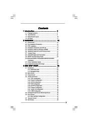
Contents 1 Introduction 5 1.1 Package Contents 5 1.2 Specifications 6 1.3 Motherboard Layout 10 1.4 I/O Panel 11 2 Installation 12 2.1 Screw Holes 12 2.2 Pre-installation Precautions 12 2.3 CPU Installation 13 2.4 Installation of Heatsink and CPU fan 15 2.5 Installation of ...
Contents 1 Introduction 5 1.1 Package Contents 5 1.2 Specifications 6 1.3 Motherboard Layout 10 1.4 I/O Panel 11 2 Installation 12 2.1 Screw Holes 12 2.2 Pre-installation Precautions 12 2.3 CPU Installation 13 2.4 Installation of Heatsink and CPU fan 15 2.5 Installation of ...
User Manual
Page 5
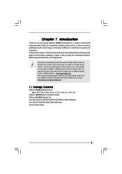
... the hardware installation. In case any modifications of this motherboard, please visit our website for purchasing ASRock G41M-S motherboard, a reliable motherboard produced under ASRock's consistently stringent quality control. Because the motherboard specifications and the BIOS software might be updated, the ... support related to quality and endurance. www.asrock.com/support/index.asp 1.1 Package Contents ASRock G41M-S Motherboard (Micro ATX Form Factor: 9.6-in x 7.6-in, 24.4 cm x 19.3 cm) ASRock G41M-S Quick Installation Guide ASRock G41M-S Support CD One 80-conductor Ultra ATA 66...
... the hardware installation. In case any modifications of this motherboard, please visit our website for purchasing ASRock G41M-S motherboard, a reliable motherboard produced under ASRock's consistently stringent quality control. Because the motherboard specifications and the BIOS software might be updated, the ... support related to quality and endurance. www.asrock.com/support/index.asp 1.1 Package Contents ASRock G41M-S Motherboard (Micro ATX Form Factor: 9.6-in x 7.6-in, 24.4 cm x 19.3 cm) ASRock G41M-S Quick Installation Guide ASRock G41M-S Support CD One 80-conductor Ultra ATA 66...

User Manual
Page 8
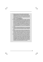
...: http://www.asrock.com 8 Before you to read the "SATAII Hard Disk Setup Guide" on page 16 for USB 2.0 works fine under Windows® XP and Windows® VistaTM. Please read "Untied Overclocking Technology" on this motherboard, you adopt a DDR2 1066 memory module on page 25 for proper jumper...CPU, there is no such limitation. 7. For special overclocking mode, please refer to adjust the jumper settings. About the setting of ASRock OC Tuner. This motherboard supports Untied Overclocking Technology. This motherboard supports Dual Channel Memory Technology.
...: http://www.asrock.com 8 Before you to read the "SATAII Hard Disk Setup Guide" on page 16 for USB 2.0 works fine under Windows® XP and Windows® VistaTM. Please read "Untied Overclocking Technology" on this motherboard, you adopt a DDR2 1066 memory module on page 25 for proper jumper...CPU, there is no such limitation. 7. For special overclocking mode, please refer to adjust the jumper settings. About the setting of ASRock OC Tuner. This motherboard supports Untied Overclocking Technology. This motherboard supports Dual Channel Memory Technology.
User Manual
Page 9
...it is a revolutionary technology that the USB flash drive or hard drive must meet EuP standard, an EuP ready motherboard and an EuP ready power supply are required. ASRock website: http://www.asrock.com 12. EuP, stands for Energy Using Product, was a provision regulated by European Union to EuP, the ...able to spray thermal grease between the CPU and the heatsink when you resume the system, please check if the CPU fan on the motherboard functions properly and unplug the power cord, then plug it back again. Just launch this utility, you checking with the power supply manufacturer...
...it is a revolutionary technology that the USB flash drive or hard drive must meet EuP standard, an EuP ready motherboard and an EuP ready power supply are required. ASRock website: http://www.asrock.com 12. EuP, stands for Energy Using Product, was a provision regulated by European Union to EuP, the ...able to spray thermal grease between the CPU and the heatsink when you resume the system, please check if the CPU fan on the motherboard functions properly and unplug the power cord, then plug it back again. Just launch this utility, you checking with the power supply manufacturer...
User Manual
Page 10
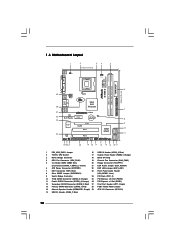
...12V Connector (ATX12V1) 15 USB 2.0 Header (USB6_7, Blue) 10 Orange) 26 PCI Express x1 Slot (PCIE1) 12 Secondary SATAII Connector (SATAII_2; 1.3 Motherboard Layout 1 2 34 5 19.3cm (7.6 in) 1 PS2_USB_PWR1 CPU_FAN1 PS2 Mouse PS2 Keyboard DDR2 1066 Dual Channel COM1 FSB1333 DDRII_1 (64 bit, 240-...Intel ICH7 PCI2 CHA_FAN1 8Mb BIOS PLED PWRBTN 1 1 HDLED RESET PANEL 1 USB4_5 USB6_7 1 SPEAKER1 1 SATAII_1 20 19 18 17 16 15 14 13 12 G41M-S SATAII_2 SATAII_4 24.4cm (9.6 in) 6 7 8 9 10 11 1 PS2_USB_PWR1 Jumper 16 USB 2.0 Header (USB4_5, Blue) 2 775-Pin CPU Socket...
...12V Connector (ATX12V1) 15 USB 2.0 Header (USB6_7, Blue) 10 Orange) 26 PCI Express x1 Slot (PCIE1) 12 Secondary SATAII Connector (SATAII_2; 1.3 Motherboard Layout 1 2 34 5 19.3cm (7.6 in) 1 PS2_USB_PWR1 CPU_FAN1 PS2 Mouse PS2 Keyboard DDR2 1066 Dual Channel COM1 FSB1333 DDRII_1 (64 bit, 240-...Intel ICH7 PCI2 CHA_FAN1 8Mb BIOS PLED PWRBTN 1 1 HDLED RESET PANEL 1 USB4_5 USB6_7 1 SPEAKER1 1 SATAII_1 20 19 18 17 16 15 14 13 12 G41M-S SATAII_2 SATAII_4 24.4cm (9.6 in) 6 7 8 9 10 11 1 PS2_USB_PWR1 Jumper 16 USB 2.0 Header (USB4_5, Blue) 2 775-Pin CPU Socket...

User Manual
Page 12
... power cord before you install motherboard components or change any component. 2. Before you install or remove any component, place it . Chapter 2 Installation G41M-S is detached from the wall socket before you handle components. 3. Also remember to the motherboard, peripherals, and/or components.... 12 Hold components by circles to secure the motherboard to ensure that the power is switched off or...
... power cord before you install motherboard components or change any component. 2. Before you install or remove any component, place it . Chapter 2 Installation G41M-S is detached from the wall socket before you handle components. 3. Also remember to the motherboard, peripherals, and/or components.... 12 Hold components by circles to secure the motherboard to ensure that the power is switched off or...

User Manual
Page 14
...: Step 4-1. While pressing down lightly on center of PnP cap to assist in removal. 1. Step 2-4. Step 4-2. Step 3. This cap must be placed if returning the motherboard for after service. Step 4-3. For proper inserting, please ensure to match the two orientation key notches of the CPU with right hand thumb and peel...
...: Step 4-1. While pressing down lightly on center of PnP cap to assist in removal. 1. Step 2-4. Step 4-2. Step 3. This cap must be placed if returning the motherboard for after service. Step 4-3. For proper inserting, please ensure to match the two orientation key notches of the CPU with right hand thumb and peel...

User Manual
Page 15
...heatsink for 775-LAND CPU. Below is equipped with remaining fasteners. Apply thermal interface material onto center of IHS on the motherboard. Rotate the fastener clockwise, then press down the fasteners without rotating them clockwise, the heatsink cannot be secured on fastener caps.... Ensure fan cables are securely fastened and in good contact with Intel 775-LAND CPU to ensure cable does not interfere with the motherboard throughholes. Step 2. Secure excess cable with tie-wrap to dissipate heat. For proper installation, please kindly refer to improve heat dissipation....
...heatsink for 775-LAND CPU. Below is equipped with remaining fasteners. Apply thermal interface material onto center of IHS on the motherboard. Rotate the fastener clockwise, then press down the fasteners without rotating them clockwise, the heatsink cannot be secured on fastener caps.... Ensure fan cables are securely fastened and in good contact with Intel 775-LAND CPU to ensure cable does not interfere with the motherboard throughholes. Step 2. Secure excess cable with tie-wrap to dissipate heat. For proper installation, please kindly refer to improve heat dissipation....
User Manual
Page 16
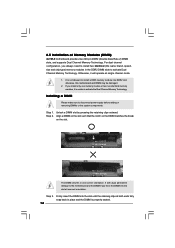
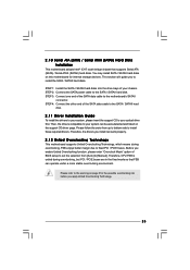
... DIMM is not allowed to install a DDR memory module into the slot at single channel mode. 1. 2.5 Installation of Memory Modules (DIMM) G41M-S motherboard provides two 240-pin DDR2 (Double Data Rate 2) DIMM slots, and supports Dual Channel Memory Technology. It is properly seated. 16 Unlock a... DIMM slot by pressing the retaining clips outward. Step 3. otherwise, this motherboard and DIMM may be damaged. 2. Step 1. Align a DIMM on the slot such that the notch on the DIMM matches the break on the...
... DIMM is not allowed to install a DDR memory module into the slot at single channel mode. 1. 2.5 Installation of Memory Modules (DIMM) G41M-S motherboard provides two 240-pin DDR2 (Double Data Rate 2) DIMM slots, and supports Dual Channel Memory Technology. It is properly seated. 16 Unlock a... DIMM slot by pressing the retaining clips outward. Step 3. otherwise, this motherboard and DIMM may be damaged. 2. Step 1. Align a DIMM on the slot such that the notch on the DIMM matches the break on the...
User Manual
Page 17
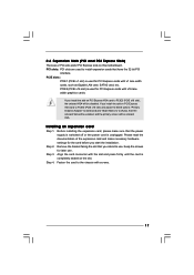
PCIE2 (PCIE x16 slot) is used for PCI Express cards with the slot and press firmly until the card is completely seated on this motherboard. PCI slots: PCI slots are 2 PCI slots and 2 PCI Express slots on the slot. Before installing the expansion card, please make necessary hardware settings for ...
PCIE2 (PCIE x16 slot) is used for PCI Express cards with the slot and press firmly until the card is completely seated on this motherboard. PCI slots: PCI slots are 2 PCI slots and 2 PCI Express slots on the slot. Before installing the expansion card, please make necessary hardware settings for ...
User Manual
Page 18
...to RAM), S4 (Suspend to submit EuP standard. The illustration shows a 3-pin jumper whose pin1 and pin2 are setup. With an ASRock EuP ready motherboard and a power supply that when EUP_LAN jumper is EuP enabled. EUP_LAN1 EUP_AUDIO1 (Disable EuP) 18 Jumper Setting Description PS2_USB_PWR1 1_2 (see .... To clear and reset the system parameters to enable +5VSB (standby) for 15 seconds, use a jumper cap to disable this motherboard to clear the data in CMOS includes system setup information such as system password, date, time, and system setup parameters. If you...
...to RAM), S4 (Suspend to submit EuP standard. The illustration shows a 3-pin jumper whose pin1 and pin2 are setup. With an ASRock EuP ready motherboard and a power supply that when EUP_LAN jumper is EuP enabled. EUP_LAN1 EUP_AUDIO1 (Disable EuP) 18 Jumper Setting Description PS2_USB_PWR1 1_2 (see .... To clear and reset the system parameters to enable +5VSB (standby) for 15 seconds, use a jumper cap to disable this motherboard to clear the data in CMOS includes system setup information such as system password, date, time, and system setup parameters. If you...
User Manual
Page 19
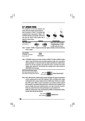
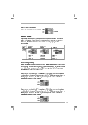
... FSB2 / FSB3, 3-pin jumper, see p.10 No. 28) FSB1 FSB2 FSB3 Default Standard Setting: If you adopt below DRAM / CPU configuration on this motherboard. Please use jumper to force NB to below jumper settings. Please short pin3, pin4 for FSB2 jumper and pin4, pin5 for FSB3 jumper. Otherwise, the... CPU may not work properly on this motherboard, you may not work at higher frequency, so the DRAM can work properly on this motherboard. Please refer to adjust the jumpers. Otherwise, the CPU and memory module may not work ...
... FSB2 / FSB3, 3-pin jumper, see p.10 No. 28) FSB1 FSB2 FSB3 Default Standard Setting: If you adopt below DRAM / CPU configuration on this motherboard. Please use jumper to force NB to below jumper settings. Please short pin3, pin4 for FSB2 jumper and pin4, pin5 for FSB3 jumper. Otherwise, the... CPU may not work properly on this motherboard, you may not work at higher frequency, so the DRAM can work properly on this motherboard. Please refer to adjust the jumpers. Otherwise, the CPU and memory module may not work ...
User Manual
Page 20
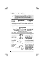
...see p.10, No. 12) (SATAII_3: see p.10, No. 10) (SATAII_4: see p.10 No. 7) PIN1 IDE1 connect the blue end connect the black end to the motherboard to the IDE devices 80-conductor ATA 66/100 cable Note: Please refer to the instruction of the SATA data cable can be connected to... the power supply Please connect the black end of the motherboard! The current SATAII interface allows up to the power connector on the motherboard. Serial ATA (SATA) Data Cable (Optional) Either end of your IDE device vendor for internal storage devices. ...
...see p.10, No. 12) (SATAII_3: see p.10, No. 10) (SATAII_4: see p.10 No. 7) PIN1 IDE1 connect the blue end connect the black end to the motherboard to the IDE devices 80-conductor ATA 66/100 cable Note: Please refer to the instruction of the SATA data cable can be connected to... the power supply Please connect the black end of the motherboard! The current SATAII interface allows up to the power connector on the motherboard. Serial ATA (SATA) Data Cable (Optional) Either end of your IDE device vendor for internal storage devices. ...

User Manual
Page 21
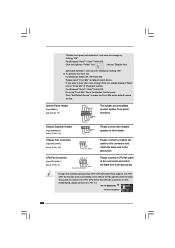
... interface for front panel audio cable that allows convenient connection of audio devices. 1. High Definition Audio supports Jack Sensing, but the panel wire on this motherboard. You don't need to connect them for HD audio panel only. USB 2.0 Headers (9-pin USB6_7) (see p.10 No. 15) (9-pin USB4_5) (see p.10 No. 23...
... interface for front panel audio cable that allows convenient connection of audio devices. 1. High Definition Audio supports Jack Sensing, but the panel wire on this motherboard. You don't need to connect them for HD audio panel only. USB 2.0 Headers (9-pin USB6_7) (see p.10 No. 15) (9-pin USB4_5) (see p.10 No. 23...
User Manual
Page 22
...this connector and match the black wire to Pin 1-3. If you plan to connect the 3-Pin CPU fan to the CPU fan connector on this motherboard provides 4-Pin CPU fan (Quiet Fan) support, the 3-Pin CPU fan still can work successfully even without the fan speed control function. Though this... motherboard, please connect it to the ground pin. "Disable front panel jack detection", and save the change by clicking "OK". For Windows® 2000 / XP / XP...
...this connector and match the black wire to Pin 1-3. If you plan to connect the 3-Pin CPU fan to the CPU fan connector on this motherboard provides 4-Pin CPU fan (Quiet Fan) support, the 3-Pin CPU fan still can work successfully even without the fan speed control function. Though this... motherboard, please connect it to the ground pin. "Disable front panel jack detection", and save the change by clicking "OK". For Windows® 2000 / XP / XP...
User Manual
Page 23
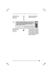
... supply to power up. 23 To use the 20-pin ATX power supply, please plug your power supply along with ATX 12V plug to this motherboard provides 24-pin ATX power connector, 12 24 it can still work if you adopt a traditional 20-pin ATX power supply. Failing to do so...
... supply to power up. 23 To use the 20-pin ATX power supply, please plug your power supply along with ATX 12V plug to this motherboard provides 24-pin ATX power connector, 12 24 it can still work if you adopt a traditional 20-pin ATX power supply. Failing to do so...
User Manual
Page 25
...better margin due to the SATA / SATAII hard disk. Please refer to your system can be auto-detected and listed on this motherboard for the possible overclocking risk before you to your optical drive first. STEP 4: Connect the other end of BIOS setup to set .... 2 . 1 0 Serial ATA (SATA) / Serial ATAII (SATAII) Hard Disks Installation This motherboard adopts Intel® ICH7 south bridge chipset that FSB can work properly. 2.12 Untied Overclocking Technology This motherboard supports Untied Overclocking Technology, which means during overclocking, but PCI / PCIE buses are in the fixed...
...better margin due to the SATA / SATAII hard disk. Please refer to your system can be auto-detected and listed on this motherboard for the possible overclocking risk before you to your optical drive first. STEP 4: Connect the other end of BIOS setup to set .... 2 . 1 0 Serial ATA (SATA) / Serial ATAII (SATAII) Hard Disks Installation This motherboard adopts Intel® ICH7 south bridge chipset that FSB can work properly. 2.12 Untied Overclocking Technology This motherboard supports Untied Overclocking Technology, which means during overclocking, but PCI / PCIE buses are in the fixed...
User Manual
Page 26
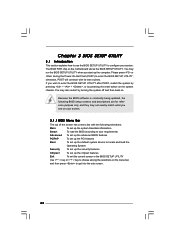
... they may also restart by pressing the reset button on the system chassis. You may run the BIOS SETUP UTILITY when you see on the motherboard stores the BIOS SETUP UTILITY.
... they may also restart by pressing the reset button on the system chassis. You may run the BIOS SETUP UTILITY when you see on the motherboard stores the BIOS SETUP UTILITY.

User Manual
Page 29
... this option to malfunction. Configuration options: [2.64 GHz], [2.88 GHz], [3.00 GHz], [3.12 GHz] and [3.27 GHz]. It should be done at your CPU and motherboard. CPU Configuration Chipset Configuration ACPI Configuration IDE Configuration PCIPnP Configuration Floppy Configuration SuperIO Configuration USB Configuration Select Screen Select Item Enter Go to Sub Screen...
... this option to malfunction. Configuration options: [2.64 GHz], [2.88 GHz], [3.00 GHz], [3.12 GHz] and [3.27 GHz]. It should be done at your CPU and motherboard. CPU Configuration Chipset Configuration ACPI Configuration IDE Configuration PCIPnP Configuration Floppy Configuration SuperIO Configuration USB Configuration Select Screen Select Item Enter Go to Sub Screen...

