
User Manual
Page 10
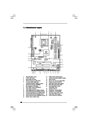
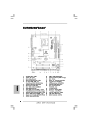
... PWRBTN 1 1 HDLED RESET PANEL 1 USB4_5 USB6_7 1 SPEAKER1 1 SATAII_1 20 19 18 17 16 15 14 13 12 G41M-S SATAII_2 SATAII_4 24.4cm (9.6 in) 6 7 8 9 10 11 1 PS2_USB_PWR1 Jumper 16 USB 2.0 Header (USB4_5, Blue) 2 775-Pin CPU Socket 17 System Panel Header (PANEL1, Orange) 3 North Bridge Controller 18 BIOS SPI Chip 4 CPU Fan Connector (CPU_FAN1...
... PWRBTN 1 1 HDLED RESET PANEL 1 USB4_5 USB6_7 1 SPEAKER1 1 SATAII_1 20 19 18 17 16 15 14 13 12 G41M-S SATAII_2 SATAII_4 24.4cm (9.6 in) 6 7 8 9 10 11 1 PS2_USB_PWR1 Jumper 16 USB 2.0 Header (USB4_5, Blue) 2 775-Pin CPU Socket 17 System Panel Header (PANEL1, Orange) 3 North Bridge Controller 18 BIOS SPI Chip 4 CPU Fan Connector (CPU_FAN1...

User Manual
Page 13
...Step 1-3. black line black line Step 2-2. Pin1 orientation key notch orientation key notch Pin1 alignment key alignment key 775-LAND CPU 775-Pin Socket 13 Open the socket: CPU Marked Corner Step 1-1. Locate Pin1 and the two orientation key notches. Orient the CPU with black lines....Integrated Heat Sink) up. 2.3 CPU Installation For the installation of Intel 775-LAND CPU, please follow the steps below. 775-Pin Socket Overview Before you insert the 775-LAND CPU into the socket if above situation is any bent pin on the ShoockoetkMatrokedcCleoranerr retention tab. ...
...Step 1-3. black line black line Step 2-2. Pin1 orientation key notch orientation key notch Pin1 alignment key alignment key 775-LAND CPU 775-Pin Socket 13 Open the socket: CPU Marked Corner Step 1-1. Locate Pin1 and the two orientation key notches. Orient the CPU with black lines....Integrated Heat Sink) up. 2.3 CPU Installation For the installation of Intel 775-LAND CPU, please follow the steps below. 775-Pin Socket Overview Before you insert the 775-LAND CPU into the socket if above situation is any bent pin on the ShoockoetkMatrokedcCleoranerr retention tab. ...

User Manual
Page 15
...be secured on the motherboard. Step 6. For proper installation, please kindly refer to illustrate the installation of IHS on fastener caps with 775-Pin socket that the CPU and the heatsink are oriented on the motherboard (CPU_FAN1, see page 10, No. 4). Repeat with the motherboard ... motherboard. Connect fan header with each other components. 15 Apply thermal interface material onto center of the heatsink for 775-LAND CPU. Place the heatsink onto the socket. Step 5. Step 2. Align fasteners with remaining fasteners. Step 1. Then connect the CPU fan to the CPU...
...be secured on the motherboard. Step 6. For proper installation, please kindly refer to illustrate the installation of IHS on fastener caps with 775-Pin socket that the CPU and the heatsink are oriented on the motherboard (CPU_FAN1, see page 10, No. 4). Repeat with the motherboard ... motherboard. Connect fan header with each other components. 15 Apply thermal interface material onto center of the heatsink for 775-LAND CPU. Place the heatsink onto the socket. Step 5. Step 2. Align fasteners with remaining fasteners. Step 1. Then connect the CPU fan to the CPU...
Quick Installation Guide
Page 2
...FSB2 / FSB3 Jumper 14 Chassis Speaker Header (SPEAKER 1, Purple) 29 ATX 12V Connector (ATX12V1) 15 USB 2.0 Header (USB6_7, Blue) 2 ASRock G41M-S Motherboard Red) 27 Print Port Header (LPT1, Purple) 13 Primary SATAII Connector (SATAII_1; Yellow) 21 EUP Audio Jumper (EUP_AUDIO1) 6 ATX ... x16 Slot (PCIE2) 11 Fourth SATAII Connector (SATAII_4; Motherboard Layout English 1 PS2_USB_PWR1 Jumper 16 USB 2.0 Header (USB4_5, Blue) 2 775-Pin CPU Socket 17 System Panel Header (PANEL1, Orange) 3 North Bridge Controller 18 BIOS SPI Chip 4 CPU Fan Connector (CPU_FAN1) 19 Chassis Fan ...
...FSB2 / FSB3 Jumper 14 Chassis Speaker Header (SPEAKER 1, Purple) 29 ATX 12V Connector (ATX12V1) 15 USB 2.0 Header (USB6_7, Blue) 2 ASRock G41M-S Motherboard Red) 27 Print Port Header (LPT1, Purple) 13 Primary SATAII Connector (SATAII_1; Yellow) 21 EUP Audio Jumper (EUP_AUDIO1) 6 ATX ... x16 Slot (PCIE2) 11 Fourth SATAII Connector (SATAII_4; Motherboard Layout English 1 PS2_USB_PWR1 Jumper 16 USB 2.0 Header (USB4_5, Blue) 2 775-Pin CPU Socket 17 System Panel Header (PANEL1, Orange) 3 North Bridge Controller 18 BIOS SPI Chip 4 CPU Fan Connector (CPU_FAN1) 19 Chassis Fan ...
Quick Installation Guide
Page 9
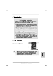
... motherboard components due to insert the CPU into the socket if above situation is any component. Hold components by the edges and do not over-tighten the screws! Otherwise, the CPU will be seriously damaged. 9 ASRock G41M-S Motherboard English Also remember to use a grounded wrist...or in the bag that comes with the component. 5. 2. Installation Pre-installation Precautions Take note of Intel 775-LAND CPU, please follow the steps below. 775-Pin Socket Overview Before you uninstall any motherboard settings. 1. Failure to do so may damage the motherboard. 2.1 CPU ...
... motherboard components due to insert the CPU into the socket if above situation is any component. Hold components by the edges and do not over-tighten the screws! Otherwise, the CPU will be seriously damaged. 9 ASRock G41M-S Motherboard English Also remember to use a grounded wrist...or in the bag that comes with the component. 5. 2. Installation Pre-installation Precautions Take note of Intel 775-LAND CPU, please follow the steps below. 775-Pin Socket Overview Before you uninstall any motherboard settings. 1. Failure to do so may damage the motherboard. 2.1 CPU ...
Quick Installation Guide
Page 10
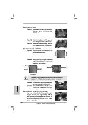
... key notches. Step 3. Pin1 orientation key notch orientation key notch Pin1 alignment key alignment key 775-LAND CPU 775-Pin Socket For proper inserting, please ensure to assist in removal. 10 ASRock G41M-S Motherboard Step 1. Disengaging the lever by depressing down and out on center of PnP cap... to match the two orientation key notches of the socket. Orient the CPU with the two alignment ...
... key notches. Step 3. Pin1 orientation key notch orientation key notch Pin1 alignment key alignment key 775-LAND CPU 775-Pin Socket For proper inserting, please ensure to assist in removal. 10 ASRock G41M-S Motherboard Step 1. Disengaging the lever by depressing down and out on center of PnP cap... to match the two orientation key notches of the socket. Orient the CPU with the two alignment ...
Quick Installation Guide
Page 11
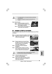
...775-LAND CPU. This cap must be secured on side closest to handle and avoid kicking off the PnP cap. 2. Step 4. Step 4-3. It is an example to the instruction manuals of IHS on the motherboard. Align fasteners with fan operation or contact other components. 11 ASRock G41M...-S Motherboard English 1. Secure load lever with thumb to ensure cable does not interfere with the motherboard throughholes. Step 1. Apply thermal interface material onto center of your CPU fan and heatsink. Step 3. Place the heatsink onto the socket. Rotate the...
...775-LAND CPU. This cap must be secured on side closest to handle and avoid kicking off the PnP cap. 2. Step 4. Step 4-3. It is an example to the instruction manuals of IHS on the motherboard. Align fasteners with fan operation or contact other components. 11 ASRock G41M...-S Motherboard English 1. Secure load lever with thumb to ensure cable does not interfere with the motherboard throughholes. Step 1. Apply thermal interface material onto center of your CPU fan and heatsink. Step 3. Place the heatsink onto the socket. Rotate the...