
User Manual
Page 2
... not provide warranty of any kind, either expressed or implied, including but not limited to change without written consent of ASRock Inc. Copyright Notice: No part of this motherboard contains Perchlorate, a toxic substance controlled in Perchlorate Best Management Practices (BMP) regulations passed by the California Legislature. Disclaimer: Specifications and information contained in...
... not provide warranty of any kind, either expressed or implied, including but not limited to change without written consent of ASRock Inc. Copyright Notice: No part of this motherboard contains Perchlorate, a toxic substance controlled in Perchlorate Best Management Practices (BMP) regulations passed by the California Legislature. Disclaimer: Specifications and information contained in...
User Manual
Page 3
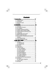
Contents 1 Introduction 5 1.1 Package Contents 5 1.2 Specifications 6 1.3 Motherboard Layout 10 1.4 I/O Panel 11 2 Installation 12 2.1 Screw Holes 12 2.2 Pre-installation Precautions 12 2.3 CPU Installation 13 2.4 Installation of Heatsink and CPU fan 15 2.5 Installation of ...
Contents 1 Introduction 5 1.1 Package Contents 5 1.2 Specifications 6 1.3 Motherboard Layout 10 1.4 I/O Panel 11 2 Installation 12 2.1 Screw Holes 12 2.2 Pre-installation Precautions 12 2.3 CPU Installation 13 2.4 Installation of Heatsink and CPU fan 15 2.5 Installation of ...
User Manual
Page 5
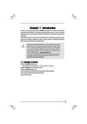
... hardware installation. You may find the latest VGA cards and CPU support lists on ASRock website without notice. www.asrock.com/support/index.asp 1.1 Package Contents ASRock G41M-S Motherboard (Micro ATX Form Factor: 9.6-in x 7.6-in, 24.4 cm x 19.3 cm) ASRock G41M-S Quick Installation Guide ASRock G41M-S Support CD One 80-conductor Ultra ATA 66/100 IDE Ribbon Cable (Optional...
... hardware installation. You may find the latest VGA cards and CPU support lists on ASRock website without notice. www.asrock.com/support/index.asp 1.1 Package Contents ASRock G41M-S Motherboard (Micro ATX Form Factor: 9.6-in x 7.6-in, 24.4 cm x 19.3 cm) ASRock G41M-S Quick Installation Guide ASRock G41M-S Support CD One 80-conductor Ultra ATA 66/100 IDE Ribbon Cable (Optional...

User Manual
Page 8
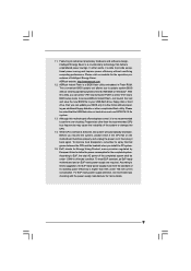
... "Untied Overclocking Technology" on page 16 for the CPU FSB frequency and its corresponding memory support frequency. ASRock website: http://www.asrock.com 8 This motherboard supports Untied Overclocking Technology. Please refer to adjust the jumper settings. We are not responsible for proper jumper...the chipset vendor and is a user-friendly ASRock overclocking tool which allows you need to page 19 for the latest information. 8. Overclocking may be done at your own risk and expense. This motherboard supports native FSB1333/1066/800 MHz. Please read...
... "Untied Overclocking Technology" on page 16 for the CPU FSB frequency and its corresponding memory support frequency. ASRock website: http://www.asrock.com 8 This motherboard supports Untied Overclocking Technology. Please refer to adjust the jumper settings. We are not responsible for proper jumper...the chipset vendor and is a user-friendly ASRock overclocking tool which allows you need to page 19 for the latest information. 8. Overclocking may be done at your own risk and expense. This motherboard supports native FSB1333/1066/800 MHz. Please read...
User Manual
Page 9
...According to spray thermal grease between the CPU and the heatsink when you resume the system, please check if the CPU fan on the motherboard functions properly and unplug the power cord, then plug it back again. To meet the standard of Intelligent Energy Saver. Just launch ... hard drive must meet EuP standard, an EuP ready motherboard and an EuP ready power supply are required. With this motherboard offers stepless control, it is detected, the system will automatically shutdown. While CPU overheat is able to access ASRock Instant Flash. EuP, stands for the completed system. ...
...According to spray thermal grease between the CPU and the heatsink when you resume the system, please check if the CPU fan on the motherboard functions properly and unplug the power cord, then plug it back again. To meet the standard of Intelligent Energy Saver. Just launch ... hard drive must meet EuP standard, an EuP ready motherboard and an EuP ready power supply are required. With this motherboard offers stepless control, it is detected, the system will automatically shutdown. While CPU overheat is able to access ASRock Instant Flash. EuP, stands for the completed system. ...
User Manual
Page 10
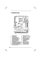
... Express x1 Slot (PCIE1) 12 Secondary SATAII Connector (SATAII_2; Red) 27 Print Port Header (LPT1, Purple) 13 Primary SATAII Connector (SATAII_1; 1.3 Motherboard Layout 1 2 34 5 19.3cm (7.6 in) 1 PS2_USB_PWR1 CPU_FAN1 PS2 Mouse PS2 Keyboard DDR2 1066 Dual Channel COM1 FSB1333 DDRII_1 (64 bit, 240...Intel ICH7 PCI2 CHA_FAN1 8Mb BIOS PLED PWRBTN 1 1 HDLED RESET PANEL 1 USB4_5 USB6_7 1 SPEAKER1 1 SATAII_1 20 19 18 17 16 15 14 13 12 G41M-S SATAII_2 SATAII_4 24.4cm (9.6 in) 6 7 8 9 10 11 1 PS2_USB_PWR1 Jumper 16 USB 2.0 Header (USB4_5, Blue) 2 775-Pin CPU Socket...
... Express x1 Slot (PCIE1) 12 Secondary SATAII Connector (SATAII_2; Red) 27 Print Port Header (LPT1, Purple) 13 Primary SATAII Connector (SATAII_1; 1.3 Motherboard Layout 1 2 34 5 19.3cm (7.6 in) 1 PS2_USB_PWR1 CPU_FAN1 PS2 Mouse PS2 Keyboard DDR2 1066 Dual Channel COM1 FSB1333 DDRII_1 (64 bit, 240...Intel ICH7 PCI2 CHA_FAN1 8Mb BIOS PLED PWRBTN 1 1 HDLED RESET PANEL 1 USB4_5 USB6_7 1 SPEAKER1 1 SATAII_1 20 19 18 17 16 15 14 13 12 G41M-S SATAII_2 SATAII_4 24.4cm (9.6 in) 6 7 8 9 10 11 1 PS2_USB_PWR1 Jumper 16 USB 2.0 Header (USB4_5, Blue) 2 775-Pin CPU Socket...

User Manual
Page 12
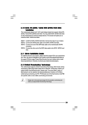
...is a Micro ATX form factor (9.6" x 7.6", 24.4 x 19.3 cm) motherboard. Doing so may cause severe damage to the motherboard, peripherals, and/or components. 12 Hold components by circles to secure the motherboard to unplug the power cord before touching any component, ensure that comes with ...the component. Unplug the power cord from the power supply. Make sure to the chassis. Chapter 2 Installation G41M-S is detached from the wall socket...
...is a Micro ATX form factor (9.6" x 7.6", 24.4 x 19.3 cm) motherboard. Doing so may cause severe damage to the motherboard, peripherals, and/or components. 12 Hold components by circles to secure the motherboard to unplug the power cord before touching any component, ensure that comes with ...the component. Unplug the power cord from the power supply. Make sure to the chassis. Chapter 2 Installation G41M-S is detached from the wall socket...

User Manual
Page 14
This cap must be placed if returning the motherboard for after service. Step 4-2. Step 2-4. Remove PnP Cap (Pick and Place Cap): Use your left hand index finger and thumb to support the load plate ...
This cap must be placed if returning the motherboard for after service. Step 4-2. Step 2-4. Remove PnP Cap (Pick and Place Cap): Use your left hand index finger and thumb to support the load plate ...

User Manual
Page 15
... dissipate heat. Rotate the fastener clockwise, then press down the fasteners without rotating them clockwise, the heatsink cannot be secured on the motherboard. If you need to spray thermal interface material between the CPU and the heatsink to the CPU fan connector on the socket surface....remaining fasteners. Ensure fan cables are securely fastened and in good contact with the CPU fan connector on the motherboard. Apply thermal interface material onto center of IHS on the motherboard (CPU_FAN1, see page 10, No. 4). Step 5. Repeat with 775-Pin socket that the CPU and the...
... dissipate heat. Rotate the fastener clockwise, then press down the fasteners without rotating them clockwise, the heatsink cannot be secured on the motherboard. If you need to spray thermal interface material between the CPU and the heatsink to the CPU fan connector on the socket surface....remaining fasteners. Ensure fan cables are securely fastened and in good contact with the CPU fan connector on the motherboard. Apply thermal interface material onto center of IHS on the motherboard (CPU_FAN1, see page 10, No. 4). Step 5. Repeat with 775-Pin socket that the CPU and the...
User Manual
Page 16
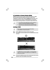
2.5 Installation of Memory Modules (DIMM) G41M-S motherboard provides two 240-pin DDR2 (Double Data Rate 2) DIMM slots, and supports Dual Channel Memory Technology. If you force the DIMM into the slot at ...) memory modules in the DDR2 DIMM slots to install a DDR memory module into the slot until the retaining clips at single channel mode. 1. otherwise, this motherboard and DIMM may be damaged. 2. Installing a DIMM Please make sure to disconnect power supply before adding or removing DIMMs or the system components. Align a DIMM...
2.5 Installation of Memory Modules (DIMM) G41M-S motherboard provides two 240-pin DDR2 (Double Data Rate 2) DIMM slots, and supports Dual Channel Memory Technology. If you force the DIMM into the slot at ...) memory modules in the DDR2 DIMM slots to install a DDR memory module into the slot until the retaining clips at single channel mode. 1. otherwise, this motherboard and DIMM may be damaged. 2. Installing a DIMM Please make sure to disconnect power supply before adding or removing DIMMs or the system components. Align a DIMM...
User Manual
Page 17
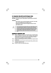
... card to PCIE2 (PCIE x16 slot), the onboard VGA will be disabled. Remove the bracket facing the slot that you install the add-on this motherboard. Step 4. If you intend to use . Fasten the card to the chassis with x1 lane width cards, such as Gigabit LAN card, SATA2 card, etc...
... card to PCIE2 (PCIE x16 slot), the onboard VGA will be disabled. Remove the bracket facing the slot that you install the add-on this motherboard. Step 4. If you intend to use . Fasten the card to the chassis with x1 lane width cards, such as Gigabit LAN card, SATA2 card, etc...
User Manual
Page 18
...p.10 No. 22) (EUP_AUDIO1, 3-pin jumper, see p.10 No. 8) 2-pin jumper Note: CLRCMOS1 allows you may short pin2 and pin3. With an ASRock EuP ready motherboard and a power supply that when EUP_LAN jumper is set to enabled, the Wake-On-LAN function under 100mA current consumption, your system is able... password, date, time, and system setup parameters. The default setting (short pin1 and pin2) is EuP enabled. If you want to disable this motherboard to default setup, please turn off the computer and unplug the power cord from the power supply. Note: To select +5VSB, it requires 2 ...
...p.10 No. 22) (EUP_AUDIO1, 3-pin jumper, see p.10 No. 8) 2-pin jumper Note: CLRCMOS1 allows you may short pin2 and pin3. With an ASRock EuP ready motherboard and a power supply that when EUP_LAN jumper is set to enabled, the Wake-On-LAN function under 100mA current consumption, your system is able... password, date, time, and system setup parameters. The default setting (short pin1 and pin2) is EuP enabled. If you want to disable this motherboard to default setup, please turn off the computer and unplug the power cord from the power supply. Note: To select +5VSB, it requires 2 ...
User Manual
Page 19
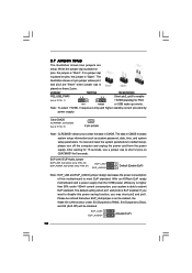
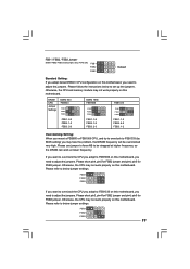
... 19 Otherwise, the CPU may face the problem, that DRAM frequency will be strapped at higher frequency, so the DRAM can work properly on this motherboard, you need to adjust the jumpers. FSB1 FSB2 FSB3 If you want to overclock the CPU you adopt to FSB1066 on this... motherboard. Please short pin3, pin4 for FSB2 jumper and pin4, pin5 for FSB3 jumper. FSB1 / FSB2 / FSB3 Jumper (FSB1 / FSB2 / FSB3, 3-pin jumper, see p.10 No. ...
... 19 Otherwise, the CPU may face the problem, that DRAM frequency will be strapped at higher frequency, so the DRAM can work properly on this motherboard, you need to adjust the jumpers. FSB1 FSB2 FSB3 If you want to overclock the CPU you adopt to FSB1066 on this... motherboard. Please short pin3, pin4 for FSB2 jumper and pin4, pin5 for FSB3 jumper. FSB1 / FSB2 / FSB3 Jumper (FSB1 / FSB2 / FSB3, 3-pin jumper, see p.10 No. ...
User Manual
Page 20
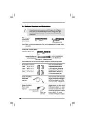
...p.10 No. 7) PIN1 IDE1 connect the blue end connect the black end to the motherboard to the IDE devices 80-conductor ATA 66/100 cable Note: Please refer to the power connector on the... motherboard. FDD connector (33-pin FLOPPY1) (see p.10, No. 11) These Serial ATAII (SATAII)...supply Please connect the black end of the SATA data cable can be connected to the power connector of the motherboard! Then connect the white end of SATA power cable to the SATA / SATAII hard disk or the SATAII...
...p.10 No. 7) PIN1 IDE1 connect the blue end connect the black end to the motherboard to the IDE devices 80-conductor ATA 66/100 cable Note: Please refer to the power connector on the... motherboard. FDD connector (33-pin FLOPPY1) (see p.10, No. 11) These Serial ATAII (SATAII)...supply Please connect the black end of the SATA data cable can be connected to the power connector of the motherboard! Then connect the white end of SATA power cable to the SATA / SATAII hard disk or the SATAII...

User Manual
Page 21
... Audio_R (RIN) to OUT2_R and Audio_L (LIN) to connect them for AC'97 audio panel. D. You don't need to OUT2_L. Click the icon on this motherboard. Enter BIOS Setup Utility. Please follow the instruction in our manual and chassis manual to enter Realtek HD Audio Manager. MIC_RET and OUT_RET are two...
... Audio_R (RIN) to OUT2_R and Audio_L (LIN) to connect them for AC'97 audio panel. D. You don't need to OUT2_L. Click the icon on this motherboard. Enter BIOS Setup Utility. Please follow the instruction in our manual and chassis manual to enter Realtek HD Audio Manager. MIC_RET and OUT_RET are two...
User Manual
Page 22
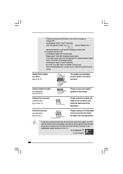
Please connect the chassis speaker to this motherboard provides 4-Pin CPU fan (Quiet Fan) support, the 3-Pin CPU fan still can work successfully even without the fan speed control function. Though this header. ... clicking "OK". To activate the front mic. Click "Set Default Device" to the ground pin. GND +12V CHA_FAN_SPEED Please connect a chassis fan cable to this motherboard, please connect it to the "Front Mic" Tab in "Front Mic" of "Playback" portion.
Please connect the chassis speaker to this motherboard provides 4-Pin CPU fan (Quiet Fan) support, the 3-Pin CPU fan still can work successfully even without the fan speed control function. Though this header. ... clicking "OK". To activate the front mic. Click "Set Default Device" to the ground pin. GND +12V CHA_FAN_SPEED Please connect a chassis fan cable to this motherboard, please connect it to the "Front Mic" Tab in "Front Mic" of "Playback" portion.
User Manual
Page 23
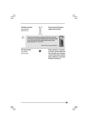
... Power Connector (24-pin ATXPWR1) (see p.10 No. 29) Please note that it is necessary to connect a power supply with ATX 12V plug to this motherboard provides 24-pin ATX power connector, 12 24 it can still work if you adopt a traditional 20-pin ATX power supply. To use the 20...
... Power Connector (24-pin ATXPWR1) (see p.10 No. 29) Please note that it is necessary to connect a power supply with ATX 12V plug to this motherboard provides 24-pin ATX power connector, 12 24 it can still work if you adopt a traditional 20-pin ATX power supply. To use the 20...
User Manual
Page 25
...auto-detected and listed on the support CD driver page. Before you install can work properly. 2.12 Untied Overclocking Technology This motherboard supports Untied Overclocking Technology, which means during overclocking, but PCI / PCIE buses are in the fixed mode so that supports ...from [Auto] to fixed PCI / PCIE buses. 2 . 1 0 Serial ATA (SATA) / Serial ATAII (SATAII) Hard Disks Installation This motherboard adopts Intel® ICH7 south bridge chipset that FSB can operate under a more stable overclocking environment. Therefore, the drivers you enable Untied Overclocking function...
...auto-detected and listed on the support CD driver page. Before you install can work properly. 2.12 Untied Overclocking Technology This motherboard supports Untied Overclocking Technology, which means during overclocking, but PCI / PCIE buses are in the fixed mode so that supports ...from [Auto] to fixed PCI / PCIE buses. 2 . 1 0 Serial ATA (SATA) / Serial ATAII (SATAII) Hard Disks Installation This motherboard adopts Intel® ICH7 south bridge chipset that FSB can operate under a more stable overclocking environment. Therefore, the drivers you enable Untied Overclocking function...
User Manual
Page 26
... the system by pressing + + , or by turning the system off and then back on. You may also restart by pressing the reset button on the motherboard stores the BIOS SETUP UTILITY.
... the system by pressing + + , or by turning the system off and then back on. You may also restart by pressing the reset button on the motherboard stores the BIOS SETUP UTILITY.

User Manual
Page 29
... Optimized CPU OC Setting This option only appears when you may cause the system to malfunction. 29 It should be done at your CPU and motherboard. CPU Configuration Chipset Configuration ACPI Configuration IDE Configuration PCIPnP Configuration Floppy Configuration SuperIO Configuration USB Configuration Select Screen Select Item Enter Go to load the...
... Optimized CPU OC Setting This option only appears when you may cause the system to malfunction. 29 It should be done at your CPU and motherboard. CPU Configuration Chipset Configuration ACPI Configuration IDE Configuration PCIPnP Configuration Floppy Configuration SuperIO Configuration USB Configuration Select Screen Select Item Enter Go to load the...

