
User Manual
Page 3
... Guide ...25 2.10 Serial ATA (SATA) / Serial ATAII (SATAII) Hard Disks Installation ...26 2.11 Driver Installation Guide ...26 2.12 Untied Overclocking Technology ...26 3 BIOS S ETUP UTILITY ...27 SETUP 3.1 Introduction ...3.1.1 BIOS Menu Bar ...3.1.2 Navigation Keys ...3.2 Main Screen ...3.3 Smart Screen ...3.4 Advanced Screen ...3.4.1 CPU Configuration ...3.4.2 Chipset Configuration ...3.4.3 ACPI Configuration ...3.4.4 IDE Configuration ...3.4.5 PCIPnP Configuration ...3.4.6 Floppy Configuration...
... Guide ...25 2.10 Serial ATA (SATA) / Serial ATAII (SATAII) Hard Disks Installation ...26 2.11 Driver Installation Guide ...26 2.12 Untied Overclocking Technology ...26 3 BIOS S ETUP UTILITY ...27 SETUP 3.1 Introduction ...3.1.1 BIOS Menu Bar ...3.1.2 Navigation Keys ...3.2 Main Screen ...3.3 Smart Screen ...3.4 Advanced Screen ...3.4.1 CPU Configuration ...3.4.2 Chipset Configuration ...3.4.3 ACPI Configuration ...3.4.4 IDE Configuration ...3.4.5 PCIPnP Configuration ...3.4.6 Floppy Configuration...
User Manual
Page 5
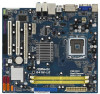
...step guide to BIOS setup and information of the Support CD. www.asrock.com/support/index.asp 1.1 P ack age Contents ackage ASRock G41M-LE Motherboard (Micro ATX Form Factor: 9.6-in x 8.6-in, 24.4 cm x 21.8 cm) ASRock G41M-LE Quick Installation Guide ASRock G41M-LE Support CD ...the hardware installation. Because the motherboard specifications and the BIOS software might be updated, the content of this motherboard, please visit our website for purchasing ASRock G41M-LE motherboard, a reliable motherboard produced under ASRock's consistently stringent quality control. You may find the ...
...step guide to BIOS setup and information of the Support CD. www.asrock.com/support/index.asp 1.1 P ack age Contents ackage ASRock G41M-LE Motherboard (Micro ATX Form Factor: 9.6-in x 8.6-in, 24.4 cm x 21.8 cm) ASRock G41M-LE Quick Installation Guide ASRock G41M-LE Support CD ...the hardware installation. Because the motherboard specifications and the BIOS software might be updated, the content of this motherboard, please visit our website for purchasing ASRock G41M-LE motherboard, a reliable motherboard produced under ASRock's consistently stringent quality control. You may find the ...

User Manual
Page 7
... Speaker/Rear Speaker/Central/Bass/ Line in header - ASRock OC Tuner (see CAUTION 11) - 8Mb AMI BIOS - Chassis Temperature Sensing - FCC, CE, WHQL * For detailed product information, please visit our website: http://www.asrock.com 7 CD in /Front Speaker/Microphone (see CAUTION... USB 2.0 headers (support 4 USB 2.0 ports) (see CAUTION 12) - AMI Legal BIOS - CPU, DRAM, NB, SB, VTT Voltage Multi-adjustment - ASRock U-COP (see CAUTION 13) - Chassis Fan Tachometer - Supports Smart BIOS - Intelligent Energy Saver (see CAUTION 15) - Hybrid Booster: - CPU Temperature Sensing -...
... Speaker/Rear Speaker/Central/Bass/ Line in header - ASRock OC Tuner (see CAUTION 11) - 8Mb AMI BIOS - Chassis Temperature Sensing - FCC, CE, WHQL * For detailed product information, please visit our website: http://www.asrock.com 7 CD in /Front Speaker/Microphone (see CAUTION... USB 2.0 headers (support 4 USB 2.0 ports) (see CAUTION 12) - AMI Legal BIOS - CPU, DRAM, NB, SB, VTT Voltage Multi-adjustment - ASRock U-COP (see CAUTION 13) - Chassis Fan Tachometer - Supports Smart BIOS - Intelligent Energy Saver (see CAUTION 15) - Hybrid Booster: - CPU Temperature Sensing -...

User Manual
Page 8
... be done at your system. For Windows ® XP 64-bit and Windows® VistaTM 7. 64-bit with overclocking, including adjusting the setting in the BIOS, applying Untied Overclocking Technology, or using the thirdparty overclocking tools. Please refer to adjust the jumpers. If you adopt a DDR2 1066 memory module on this...
... be done at your system. For Windows ® XP 64-bit and Windows® VistaTM 7. 64-bit with overclocking, including adjusting the setting in the BIOS, applying Untied Overclocking Technology, or using the thirdparty overclocking tools. Please refer to adjust the jumpers. If you adopt a DDR2 1066 memory module on this...

User Manual
Page 10
...-DVD playback support on this motherboard requires the proper hardware configuration. CPU VGA Memory Suggested OS Playback Software Intel® E5200 (BIOS option PAVP Lite mode disabled) Intel® E1200 (BIOS option PAVP Lite mode enabled) G41 onboard DX10 VGA DDR2 800 1GB x 2 Windows® VistaTM or Windows® VistaTM 64 CyberLink...
...-DVD playback support on this motherboard requires the proper hardware configuration. CPU VGA Memory Suggested OS Playback Software Intel® E5200 (BIOS option PAVP Lite mode disabled) Intel® E1200 (BIOS option PAVP Lite mode enabled) G41 onboard DX10 VGA DDR2 800 1GB x 2 Windows® VistaTM or Windows® VistaTM 64 CyberLink...
User Manual
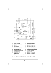
Page 11
...bit, 240-pin module) DDRII_2 (64 bit, 240-pin module) RoHS USB 2.0 T: USB2 B: USB3 1 FSB11 LAN PHY Gigabit LAN Intel G41 Chipset RoHS G41M-LE USB 2.0 T: USB0 Top: RJ-45 B: USB1 FSB3 1 FSB2 1 24.4cm (9.6 in) CHA_FAN1 SPEAKER1 PS2 Keyboard PS2 Mouse 1 PS2_USB_PWR1 VGA1 ATXPWR1 ATX12V1...PCIE1 9 10 11 PCIE2 CMOS Battery CLRCMOS1 Super I/O PCI1 Intel ICH7 1 PLED PWRBTN PANEL1 26 AUDIO CODEC 1 HDLED RESET CD1 1 PCI2 LPT1 SATAII_1 SATAII_3 8Mb BIOS USB4_5 USB6_7 HD_AUDIO1 SATAII_2 SATAII_4 12 13 14 15 1 1 FLOPPY1 1 1 25 24 23 22 21 20 19 18 17 16 1 2 3 4 5 ...
...bit, 240-pin module) DDRII_2 (64 bit, 240-pin module) RoHS USB 2.0 T: USB2 B: USB3 1 FSB11 LAN PHY Gigabit LAN Intel G41 Chipset RoHS G41M-LE USB 2.0 T: USB0 Top: RJ-45 B: USB1 FSB3 1 FSB2 1 24.4cm (9.6 in) CHA_FAN1 SPEAKER1 PS2 Keyboard PS2 Mouse 1 PS2_USB_PWR1 VGA1 ATXPWR1 ATX12V1...PCIE1 9 10 11 PCIE2 CMOS Battery CLRCMOS1 Super I/O PCI1 Intel ICH7 1 PLED PWRBTN PANEL1 26 AUDIO CODEC 1 HDLED RESET CD1 1 PCI2 LPT1 SATAII_1 SATAII_3 8Mb BIOS USB4_5 USB6_7 HD_AUDIO1 SATAII_2 SATAII_4 12 13 14 15 1 1 FLOPPY1 1 1 25 24 23 22 21 20 19 18 17 16 1 2 3 4 5 ...

User Manual
Page 18
... disabled. Remove the bracket facing the slot that you install the add-on PCI Express VGA card to PCIE2 (PCIE x16 slot) and adjust the BIOS options "Primary Graphics Adapter" to [Onboard] and "Share Memory" to [Auto], then the onboard VGA will be enabled, and the primary screen will be onboard...
... disabled. Remove the bracket facing the slot that you install the add-on PCI Express VGA card to PCIE2 (PCIE x16 slot) and adjust the BIOS options "Primary Graphics Adapter" to [Onboard] and "Share Memory" to [Auto], then the onboard VGA will be enabled, and the primary screen will be onboard...

User Manual
Page 20
... FSB1: 2-3 FSB2: 1-2 FSB3: 2-3 FSB1: 1-2 FSB2: 1-2 FSB3: 2-3 FSB1: 1-2 FSB2: 4-5 FSB3: 1-2 Overclocking Setting: When you mount a FSB800 or FSB1066 CPU, and try to overclock to FSB1333 (by BIOS setting) you may not work properly on this motherboard. Otherwise, the CPU and memory module may face the problem, that DRAM frequency will be strapped...
... FSB1: 2-3 FSB2: 1-2 FSB3: 2-3 FSB1: 1-2 FSB2: 1-2 FSB3: 2-3 FSB1: 1-2 FSB2: 4-5 FSB3: 1-2 Overclocking Setting: When you mount a FSB800 or FSB1066 CPU, and try to overclock to FSB1333 (by BIOS setting) you may not work properly on this motherboard. Otherwise, the CPU and memory module may face the problem, that DRAM frequency will be strapped...

User Manual
Page 23
...) (see p.11 No. 7) 12 24 Please connect an ATX power supply to OUT2_L. Enter Advanced Settings, and then select Chipset Configuration. DU MMY R E S ET# GND H D LE D H D LE D + Chassis Speaker Header (4-pin SPEAKER 1) (see p.11 No. 9) GND +1 2 V CHA_FAN_S P EED Please connect a chassis fan cable to this motherboard, please connect it to the ground... [Enabled]. Connect Ground (GND) to the ground pin. 2. Connect Mic_IN (MIC) to connect them for HD audio panel only. D. You don't need to MIC2_L. E. Enter BIOS Setup Utility. Please connect a CPU fan cable to this header.
...) (see p.11 No. 7) 12 24 Please connect an ATX power supply to OUT2_L. Enter Advanced Settings, and then select Chipset Configuration. DU MMY R E S ET# GND H D LE D H D LE D + Chassis Speaker Header (4-pin SPEAKER 1) (see p.11 No. 9) GND +1 2 V CHA_FAN_S P EED Please connect a chassis fan cable to this motherboard, please connect it to the ground... [Enabled]. Connect Ground (GND) to the ground pin. 2. Connect Mic_IN (MIC) to connect them for HD audio panel only. D. You don't need to MIC2_L. E. Enter BIOS Setup Utility. Please connect a CPU fan cable to this header.

User Manual
Page 26
... the SATA / SATAII hard disks. Before you to the SATA / SATAII hard disk. STEP 1: Install the SATA / SATAII hard disks into the drive bays of BIOS setup to set the selection from up to bottom side to install those required drivers. Please follow the order from [Auto] to the warning on...
... the SATA / SATAII hard disks. Before you to the SATA / SATAII hard disk. STEP 1: Install the SATA / SATAII hard disks into the drive bays of BIOS setup to set the selection from up to bottom side to install those required drivers. Please follow the order from [Auto] to the warning on...

User Manual
Page 27
... + + , or by turning the system off and then back on the menu bar, and then press to get into the sub screen. 27 Because the BIOS software is constantly being updated, the following selections: To set up the system time/date information To set up the advanced... BIOS features To display current hardware status To set up the default system device to locate and load the Operating System Security To set up the ...
... + + , or by turning the system off and then back on the menu bar, and then press to get into the sub screen. 27 Because the BIOS software is constantly being updated, the following selections: To set up the system time/date information To set up the advanced... BIOS features To display current hardware status To set up the default system device to locate and load the Operating System Security To set up the ...

User Manual
Page 28
... Advanced H/W Monitor Boot Main Smart Security Exit System Overview System Time System Date BIOS Version Processor Type : : [14:00:09] [Thu 10/02/2008] G41M-LE P1.00 Intel(R) CPU 3.20GHz (64bit) 3200MHz F64/4 4096KB Use [Enter], [TAB] or [SHIFT-TAB] to configure system Time. Use [+] or [-] to select a field. 3 . 1 . 2 Navigation ...
... Advanced H/W Monitor Boot Main Smart Security Exit System Overview System Time System Date BIOS Version Processor Type : : [14:00:09] [Thu 10/02/2008] G41M-LE P1.00 Intel(R) CPU 3.20GHz (64bit) 3200MHz F64/4 4096KB Use [Enter], [TAB] or [SHIFT-TAB] to configure system Time. Use [+] or [-] to select a field. 3 . 1 . 2 Navigation ...

User Manual
Page 29
... Saving Setup Default Load power saving setup default. Enter F1 F9 F10 ESC Select Screen Select Item Go to save the changes and exit the BIOS SETUP UTILITY. If system boot failure occurs after saving the changes. F6 key can be used for this operation. Load... BIOS Defaults Load BIOS default values for this operation. 29 F10 key can be compatible with all the setup questions. Load Performance Setup Default (IDE/SATA) This performance setup ...
... Saving Setup Default Load power saving setup default. Enter F1 F9 F10 ESC Select Screen Select Item Go to save the changes and exit the BIOS SETUP UTILITY. If system boot failure occurs after saving the changes. F6 key can be used for this operation. Load... BIOS Defaults Load BIOS default values for this operation. 29 F10 key can be compatible with all the setup questions. Load Performance Setup Default (IDE/SATA) This performance setup ...

User Manual
Page 30
...CPU Configuration, Chipset Configuration, ACPI Configuration, IDE Configuration, PCIPnP Configuration, Floppy Configuration, SuperIO Configuration, and USB Configuration. BIOS SETUP UTILITY H/W Monitor Boot Main Smart Advanced Security Exit Options for CPU Advanced Settings WARNING : Setting wrong values ... Copyright 1985-2005, American Megatrends, Inc. Overclock Mode Use this section may cause system to malfunction. 3.4.1 CPU Configuration BIOS SETUP UTILITY Advanced CPU Configuration Overclock Mode CPU Frequency (MHz) PCIE Frequency (MHz) Boot Failure Guard Spread Spectrum Ratio ...
...CPU Configuration, Chipset Configuration, ACPI Configuration, IDE Configuration, PCIPnP Configuration, Floppy Configuration, SuperIO Configuration, and USB Configuration. BIOS SETUP UTILITY H/W Monitor Boot Main Smart Advanced Security Exit Options for CPU Advanced Settings WARNING : Setting wrong values ... Copyright 1985-2005, American Megatrends, Inc. Overclock Mode Use this section may cause system to malfunction. 3.4.1 CPU Configuration BIOS SETUP UTILITY Advanced CPU Configuration Overclock Mode CPU Frequency (MHz) PCIE Frequency (MHz) Boot Failure Guard Spread Spectrum Ratio ...

User Manual
Page 32
... F10 ESC v02.54 (C) Copyright 1985-2005, American Megatrends, Inc. You may reduce CPU voltage and lead to [Disable] if above issue occurs. 3.4.2 Chipset Configuration BIOS SETUP UTILITY Advanced Chipset Configuration [Disabled] Memory Remap Feature [Auto] DRAM Frequency [Disabled] Flexibility Option Standard Memory Info : 5-5-5-15-36-5-3-3-3 [Auto] DRAM tCL [Auto] DRAM...
... F10 ESC v02.54 (C) Copyright 1985-2005, American Megatrends, Inc. You may reduce CPU voltage and lead to [Disable] if above issue occurs. 3.4.2 Chipset Configuration BIOS SETUP UTILITY Advanced Chipset Configuration [Disabled] Memory Remap Feature [Auto] DRAM Frequency [Disabled] Flexibility Option Standard Memory Info : 5-5-5-15-36-5-3-3-3 [Auto] DRAM tCL [Auto] DRAM...

User Manual
Page 35
...], [0.65 x Vtt], [0.63 x Vtt] and [0.615 x Vtt]. The default value of this to select CPU Voltage. CPU Voltage Use this feature is [Auto]. Besides the BIOS option, you want to enable or disable the "OnBoard Lan" feature. OnBoard Lan This allows you to enable this function, please set this function. 35
...], [0.65 x Vtt], [0.63 x Vtt] and [0.615 x Vtt]. The default value of this to select CPU Voltage. CPU Voltage Use this feature is [Auto]. Besides the BIOS option, you want to enable or disable the "OnBoard Lan" feature. OnBoard Lan This allows you to enable this function, please set this function. 35

User Manual
Page 36
... on the system from the power-soft-off when the power recovers. Please set the power state after an unexpected AC/Power loss. 3 . 4 . 3 ACPI Configuration BIOS SETUP UTILITY Advanced ACPI Configuration Suspend To RAM Restore on AC/Power Loss This allows you to set this item to -RAM feature. RTC Alarm...
... on the system from the power-soft-off when the power recovers. Please set the power state after an unexpected AC/Power loss. 3 . 4 . 3 ACPI Configuration BIOS SETUP UTILITY Advanced ACPI Configuration Suspend To RAM Restore on AC/Power Loss This allows you to set this item to -RAM feature. RTC Alarm...

User Manual
Page 37
3 . 4 . 4 IDE Configuration BIOS SETUP UTILITY Advanced IDE Configuration ATA/IDE Configuration SATAII_1 SATAII_2 SATAII_3 SATAII_4 IDE1 Master IDE1 Slave [Enhanced] [Hard Disk] [Not Detected] [Not Detected] [Not Detected] [...
3 . 4 . 4 IDE Configuration BIOS SETUP UTILITY Advanced IDE Configuration ATA/IDE Configuration SATAII_1 SATAII_2 SATAII_3 SATAII_4 IDE1 Master IDE1 Slave [Enhanced] [Hard Disk] [Not Detected] [Not Detected] [Not Detected] [...

User Manual
Page 38
...ESC Select Screen Select Item Change Option General Help Load Defaults Save and Exit Exit v02.54 (C) Copyright 1985-2005, American Megatrends, Inc. BIOS SETUP UTILITY Advanced Primary IDE Master Device Vendor Size LBA Mode Block Mode PIO Mode Async DMA Ultra DMA S.M.A.R.T. After selecting the hard disk ...information into BIOS, use of the IDE device that you specify. Make sure to set the PIO mode to select the LBA/Large mode for a hard ...
...ESC Select Screen Select Item Change Option General Help Load Defaults Save and Exit Exit v02.54 (C) Copyright 1985-2005, American Megatrends, Inc. BIOS SETUP UTILITY Advanced Primary IDE Master Device Vendor Size LBA Mode Block Mode PIO Mode Async DMA Ultra DMA S.M.A.R.T. After selecting the hard disk ...information into BIOS, use of the IDE device that you specify. Make sure to set the PIO mode to select the LBA/Large mode for a hard ...

User Manual
Page 39
Configuration options: [Disabled], [Auto], [Enabled]. 32-Bit Data Transfer Use this item to maximize the IDE hard disk data transfer rate. 3.4.5 PCIPnP Configuration BIOS SETUP UTILITY Advanced Advanced PCI / PnP Settings PCI Latency Timer PCI IDE BusMaster [32] [Enabled] Value in units of PCI clocks for PCI device latency ...
Configuration options: [Disabled], [Auto], [Enabled]. 32-Bit Data Transfer Use this item to maximize the IDE hard disk data transfer rate. 3.4.5 PCIPnP Configuration BIOS SETUP UTILITY Advanced Advanced PCI / PnP Settings PCI Latency Timer PCI IDE BusMaster [32] [Enabled] Value in units of PCI clocks for PCI device latency ...


