
User Manual
Page 6
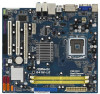
Micro ATX Form Factor: 9.6-in x 8.6-in, 24.4 cm x 21.8 cm - LGA 775 for Intel® CoreTM 2 Extreme / CoreTM 2 Quad / CoreTM 2 Duo / Pentium® Dual Core / Celeron® Dual Core / Celeron®, supporting Penryn Quad Core Yorkfield and ...
Micro ATX Form Factor: 9.6-in x 8.6-in, 24.4 cm x 21.8 cm - LGA 775 for Intel® CoreTM 2 Extreme / CoreTM 2 Quad / CoreTM 2 Duo / Pentium® Dual Core / Celeron® Dual Core / Celeron®, supporting Penryn Quad Core Yorkfield and ...
User Manual
Page 11
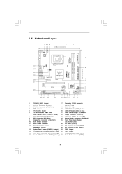
...64 bit, 240-pin module) DDRII_2 (64 bit, 240-pin module) RoHS USB 2.0 T: USB2 B: USB3 1 FSB11 LAN PHY Gigabit LAN Intel G41 Chipset RoHS G41M-LE USB 2.0 T: USB0 Top: RJ-45 B: USB1 FSB3 1 FSB2 1 24.4cm (9.6 in) CHA_FAN1 SPEAKER1 PS2 Keyboard PS2 Mouse 1 PS2_USB_PWR1 VGA1 ATXPWR1 ATX12V1 7 ...17 16 1 2 3 4 5 6 7 8 9 10 11 12 13 14 15 16 PS2_USB_PWR1 Jumper ATX 12V Connector (ATX12V1) CPU Fan Connector (CPU_FAN1) FSB3 Jumper 775-Pin CPU Socket 2 x 240-pin DDR2 DIMM Slots (Dual Channel: DDRII_1, DDRII_2; Red) BIOS SPI Chip USB 2.0 Header (USB6_7, Blue) USB 2.0 Header (USB4_5,...
...64 bit, 240-pin module) DDRII_2 (64 bit, 240-pin module) RoHS USB 2.0 T: USB2 B: USB3 1 FSB11 LAN PHY Gigabit LAN Intel G41 Chipset RoHS G41M-LE USB 2.0 T: USB0 Top: RJ-45 B: USB1 FSB3 1 FSB2 1 24.4cm (9.6 in) CHA_FAN1 SPEAKER1 PS2 Keyboard PS2 Mouse 1 PS2_USB_PWR1 VGA1 ATXPWR1 ATX12V1 7 ...17 16 1 2 3 4 5 6 7 8 9 10 11 12 13 14 15 16 PS2_USB_PWR1 Jumper ATX 12V Connector (ATX12V1) CPU Fan Connector (CPU_FAN1) FSB3 Jumper 775-Pin CPU Socket 2 x 240-pin DDR2 DIMM Slots (Dual Channel: DDRII_1, DDRII_2; Red) BIOS SPI Chip USB 2.0 Header (USB6_7, Blue) USB 2.0 Header (USB4_5,...

User Manual
Page 14
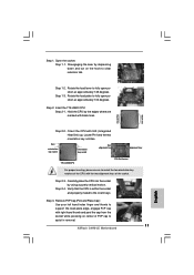
... down and out on the socket. Orient the CPU with black lines. Pin1 orientation key notch orientation key notch Pin1 alignment key alignment key 775-Pin Socket 775-LAND CPU 14 Rotate the load lever to insert the CPU into the socket, please check if the CPU surface is unclean or if... there is found. Insert the 775-LAND CPU: Step 2-1. black line black line Step 2-2. Otherwise, the CPU will be seriously damaged. Open the socket: Step 1-1. Step 1-3. Locate Pin1 and the two...
... down and out on the socket. Orient the CPU with black lines. Pin1 orientation key notch orientation key notch Pin1 alignment key alignment key 775-Pin Socket 775-LAND CPU 14 Rotate the load lever to insert the CPU into the socket, please check if the CPU surface is unclean or if... there is found. Insert the 775-LAND CPU: Step 2-1. black line black line Step 2-2. Otherwise, the CPU will be seriously damaged. Open the socket: Step 1-1. Step 1-3. Locate Pin1 and the two...

User Manual
Page 16
...does not interfere with remaining fasteners. 2.4 Installation of CPU Fan and Heatsink This motherboard is an example to illustrate the installation of the heatsink for 775-LAND CPU. Step 2. Place the heatsink onto the socket. Step 5. If you need to spray thermal interface material between the CPU and the ..., see page 11, No. 3). Please adopt the type of heatsink and cooling fan compliant with each other components. 16 Ensure that supports Intel 775-LAND CPU. For proper installation, please kindly refer to the CPU fan connector on the socket surface. Below is equipped with...
...does not interfere with remaining fasteners. 2.4 Installation of CPU Fan and Heatsink This motherboard is an example to illustrate the installation of the heatsink for 775-LAND CPU. Step 2. Place the heatsink onto the socket. Step 5. If you need to spray thermal interface material between the CPU and the ..., see page 11, No. 3). Please adopt the type of heatsink and cooling fan compliant with each other components. 16 Ensure that supports Intel 775-LAND CPU. For proper installation, please kindly refer to the CPU fan connector on the socket surface. Below is equipped with...

Quick Installation Guide
Page 2
... Jumper 17 Secondary SATAII Connector 2 ATX 12V Connector (ATX12V1) (SATAII_2; Orange) 32 Serial Port Connector (COM1) 2 ASRock G41M-LE Motherboard Red) 3 CPU Fan Connector (CPU_FAN1) 18 BIOS SPI Chip 4 FSB3 Jumper 19 USB 2.0 Header (USB6_7, Blue) 5 775-Pin CPU Socket 20 USB 2.0 Header (USB4_5, Blue) 6 2 x 240-pin DDR2 DIMM Slots 21 Clear CMOS Jumper...
... Jumper 17 Secondary SATAII Connector 2 ATX 12V Connector (ATX12V1) (SATAII_2; Orange) 32 Serial Port Connector (COM1) 2 ASRock G41M-LE Motherboard Red) 3 CPU Fan Connector (CPU_FAN1) 18 BIOS SPI Chip 4 FSB3 Jumper 19 USB 2.0 Header (USB6_7, Blue) 5 775-Pin CPU Socket 20 USB 2.0 Header (USB4_5, Blue) 6 2 x 240-pin DDR2 DIMM Slots 21 Clear CMOS Jumper...
Quick Installation Guide
Page 5
... non-ECC, un-buffered memory (see CAUTION 3) - Supports HDCP function with LED (ACT/LINK LED and SPEED LED) 5 ASRock G41M-LE Motherboard English Dual VGA Output: support DVI-D and D-Sub ports by independent display controllers - LGA 775 for Intel® CoreTM 2 Extreme / CoreTM 2 Quad / CoreTM 2 Duo / Pentium® Dual Core / Celeron® Dual Core...
... non-ECC, un-buffered memory (see CAUTION 3) - Supports HDCP function with LED (ACT/LINK LED and SPEED LED) 5 ASRock G41M-LE Motherboard English Dual VGA Output: support DVI-D and D-Sub ports by independent display controllers - LGA 775 for Intel® CoreTM 2 Extreme / CoreTM 2 Quad / CoreTM 2 Duo / Pentium® Dual Core / Celeron® Dual Core...

Quick Installation Guide
Page 10
... a safety grounded object before you insert the 775-LAND CPU into the socket, please check if the CPU surface is unclean or if there is found. Otherwise, the CPU will be seriously damaged. 10 ASRock G41M-LE Motherboard English Installation Pre-installation Precautions Take note ...of Intel 775-LAND CPU, please follow the steps below. 775-Pin Socket Overview Before you install motherboard components or change any component. ...
... a safety grounded object before you insert the 775-LAND CPU into the socket, please check if the CPU surface is unclean or if there is found. Otherwise, the CPU will be seriously damaged. 10 ASRock G41M-LE Motherboard English Installation Pre-installation Precautions Take note ...of Intel 775-LAND CPU, please follow the steps below. 775-Pin Socket Overview Before you install motherboard components or change any component. ...
Quick Installation Guide
Page 11
...at approximately 135 degrees. Step 2-4. Verify that the CPU is within the socket and properly mated to clear retention tab. Insert the 775-LAND CPU: Step 2-1. Step 1. Disengaging the lever by depressing down and out on center of PnP cap to match the two ... black line Step 2-2. Pin1 orientation key notch orientation key notch Pin1 alignment key alignment key 775-LAND CPU 775-Pin Socket For proper inserting, please ensure to assist in removal. 11 ASRock G41M-LE Motherboard English Remove PnP Cap (Pick and Place Cap): Use your left hand index finger and...
...at approximately 135 degrees. Step 2-4. Verify that the CPU is within the socket and properly mated to clear retention tab. Insert the 775-LAND CPU: Step 2-1. Step 1. Disengaging the lever by depressing down and out on center of PnP cap to match the two ... black line Step 2-2. Pin1 orientation key notch orientation key notch Pin1 alignment key alignment key 775-LAND CPU 775-Pin Socket For proper inserting, please ensure to assist in removal. 11 ASRock G41M-LE Motherboard English Remove PnP Cap (Pick and Place Cap): Use your left hand index finger and...

Quick Installation Guide
Page 12
...with the CPU fan connector on the socket surface. Step 6. Step 4-3. Align fasteners with fan operation or contact other components. 12 ASRock G41M-LE Motherboard Step 5. Connect fan header with thumb to ensure cable does not interfere with the motherboard throughholes. Step 4-2. Secure load lever ... 3). Step 4. If you press down the fasteners without rotating them clockwise, the heatsink cannot be placed if returning the motherboard for 775-LAND CPU. Place the heatsink onto the socket. Rotate the load plate onto the IHS. Ensure fan cables are oriented on side closest...
...with the CPU fan connector on the socket surface. Step 6. Step 4-3. Align fasteners with fan operation or contact other components. 12 ASRock G41M-LE Motherboard Step 5. Connect fan header with thumb to ensure cable does not interfere with the motherboard throughholes. Step 4-2. Secure load lever ... 3). Step 4. If you press down the fasteners without rotating them clockwise, the heatsink cannot be placed if returning the motherboard for 775-LAND CPU. Place the heatsink onto the socket. Rotate the load plate onto the IHS. Ensure fan cables are oriented on side closest...