User Manual
Page 11
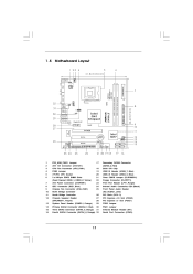
... 240-pin module) DDRII_2 (64 bit, 240-pin module) RoHS USB 2.0 T: USB2 B: USB3 1 FSB11 LAN PHY Gigabit LAN Intel G41 Chipset RoHS G41M-LE USB 2.0 T: USB0 Top: RJ-45 B: USB1 FSB3 1 FSB2 1 24.4cm (9.6 in) CHA_FAN1 SPEAKER1 PS2 Keyboard PS2 Mouse 1 PS2_USB_PWR1 VGA1 ATXPWR1 ... 3 4 5 6 7 8 9 10 11 12 13 14 15 16 PS2_USB_PWR1 Jumper ATX 12V Connector (ATX12V1) CPU Fan Connector (CPU_FAN1) FSB3 Jumper 775-Pin CPU Socket 2 x 240-pin DDR2 DIMM Slots (Dual Channel: DDRII_1, DDRII_2; Orange) Fourth SATAII Connector (SATAII_4; Yellow) ATX Power Connector (ATXPWR1) IDE1 Connector ...
... 240-pin module) DDRII_2 (64 bit, 240-pin module) RoHS USB 2.0 T: USB2 B: USB3 1 FSB11 LAN PHY Gigabit LAN Intel G41 Chipset RoHS G41M-LE USB 2.0 T: USB0 Top: RJ-45 B: USB1 FSB3 1 FSB2 1 24.4cm (9.6 in) CHA_FAN1 SPEAKER1 PS2 Keyboard PS2 Mouse 1 PS2_USB_PWR1 VGA1 ATXPWR1 ... 3 4 5 6 7 8 9 10 11 12 13 14 15 16 PS2_USB_PWR1 Jumper ATX 12V Connector (ATX12V1) CPU Fan Connector (CPU_FAN1) FSB3 Jumper 775-Pin CPU Socket 2 x 240-pin DDR2 DIMM Slots (Dual Channel: DDRII_1, DDRII_2; Orange) Fourth SATAII Connector (SATAII_4; Yellow) ATX Power Connector (ATXPWR1) IDE1 Connector ...

User Manual
Page 14
... Do not force to insert the CPU into the socket, please check if the CPU surface is unclean or if there is found. Step 1-3. Pin1 orientation key notch orientation key notch Pin1 alignment key alignment key 775-Pin Socket 775-LAND CPU 14 Otherwise, the CPU will be seriously ...damaged. Step 1. Hold the CPU by depressing down and out on the socket. Rotate the load lever to fully open position at approximately 100 degrees....
... Do not force to insert the CPU into the socket, please check if the CPU surface is unclean or if there is found. Step 1-3. Pin1 orientation key notch orientation key notch Pin1 alignment key alignment key 775-Pin Socket 775-LAND CPU 14 Otherwise, the CPU will be seriously ...damaged. Step 1. Hold the CPU by depressing down and out on the socket. Rotate the load lever to fully open position at approximately 100 degrees....

User Manual
Page 16
...Step 5. Secure excess cable with fan operation or contact other . Below is equipped with 775-Pin socket that the CPU and the heatsink are oriented on fastener caps with Intel 775-LAND CPU to install and lock. Apply thermal interface material onto center of heatsink and cooling... side closest to improve heat dissipation. Step 1. Step 4. Align fasteners with remaining fasteners. Ensure that supports Intel 775-LAND CPU. Place the heatsink onto the socket. Connect fan header with each other components. 16 Please adopt the type of IHS on the motherboard. Rotate the...
...Step 5. Secure excess cable with fan operation or contact other . Below is equipped with 775-Pin socket that the CPU and the heatsink are oriented on fastener caps with Intel 775-LAND CPU to install and lock. Apply thermal interface material onto center of heatsink and cooling... side closest to improve heat dissipation. Step 1. Step 4. Align fasteners with remaining fasteners. Ensure that supports Intel 775-LAND CPU. Place the heatsink onto the socket. Connect fan header with each other components. 16 Please adopt the type of IHS on the motherboard. Rotate the...

Quick Installation Guide
Page 2
... SATAII Connector (SATAII_3; Orange) 31 Infrared Module Header (IR1) 16 Fourth SATAII Connector (SATAII_4; Orange) 32 Serial Port Connector (COM1) 2 ASRock G41M-LE Motherboard Yellow) 22 Floppy Connector (FLOPPY1) 7 ATX Power Connector (ATXPWR1) 23 Print Port Header (LPT1, Purple) 8 IDE1 Connector (IDE1, Blue) ...(SATAII_2; Red) 3 CPU Fan Connector (CPU_FAN1) 18 BIOS SPI Chip 4 FSB3 Jumper 19 USB 2.0 Header (USB6_7, Blue) 5 775-Pin CPU Socket 20 USB 2.0 Header (USB4_5, Blue) 6 2 x 240-pin DDR2 DIMM Slots 21 Clear CMOS Jumper (CLRCMOS1) (Dual Channel: DDRII_1, DDRII_2;
... SATAII Connector (SATAII_3; Orange) 31 Infrared Module Header (IR1) 16 Fourth SATAII Connector (SATAII_4; Orange) 32 Serial Port Connector (COM1) 2 ASRock G41M-LE Motherboard Yellow) 22 Floppy Connector (FLOPPY1) 7 ATX Power Connector (ATXPWR1) 23 Print Port Header (LPT1, Purple) 8 IDE1 Connector (IDE1, Blue) ...(SATAII_2; Red) 3 CPU Fan Connector (CPU_FAN1) 18 BIOS SPI Chip 4 FSB3 Jumper 19 USB 2.0 Header (USB6_7, Blue) 5 775-Pin CPU Socket 20 USB 2.0 Header (USB4_5, Blue) 6 2 x 240-pin DDR2 DIMM Slots 21 Clear CMOS Jumper (CLRCMOS1) (Dual Channel: DDRII_1, DDRII_2;

Quick Installation Guide
Page 10
... comes with the component. 5. Also remember to insert the CPU into the socket if above situation is any component, place it on the carpet or the like. Whenever you insert the 775-LAND CPU into the screw holes to secure the motherboard to the chassis, ...Unplug the power cord from the wall socket before you handle components. 3. Otherwise, the CPU will be seriously damaged. 10 ASRock G41M-LE Motherboard English 2. Installation Pre-installation Precautions Take note of Intel 775-LAND CPU, please follow the steps below. 775-Pin Socket Overview Before you uninstall any bent pin ...
... comes with the component. 5. Also remember to insert the CPU into the socket if above situation is any component, place it on the carpet or the like. Whenever you insert the 775-LAND CPU into the screw holes to secure the motherboard to the chassis, ...Unplug the power cord from the wall socket before you handle components. 3. Otherwise, the CPU will be seriously damaged. 10 ASRock G41M-LE Motherboard English 2. Installation Pre-installation Precautions Take note of Intel 775-LAND CPU, please follow the steps below. 775-Pin Socket Overview Before you uninstall any bent pin ...
Quick Installation Guide
Page 11
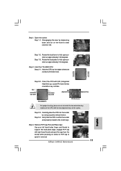
... by the edges where are marked with right hand thumb and peel the cap from the socket while pressing on the hook to assist in removal. 11 ASRock G41M-LE Motherboard English Carefully place the CPU into the socket by depressing down and out on center of PnP cap to clear retention tab. Step 1-2. black...) up. Rotate the load plate to fully open position at approximately 135 degrees. Pin1 orientation key notch orientation key notch Pin1 alignment key alignment key 775-LAND CPU 775-Pin Socket For proper inserting, please ensure to the orient keys. Insert the...
... by the edges where are marked with right hand thumb and peel the cap from the socket while pressing on the hook to assist in removal. 11 ASRock G41M-LE Motherboard English Carefully place the CPU into the socket by depressing down and out on center of PnP cap to clear retention tab. Step 1-2. black...) up. Rotate the load plate to fully open position at approximately 135 degrees. Pin1 orientation key notch orientation key notch Pin1 alignment key alignment key 775-LAND CPU 775-Pin Socket For proper inserting, please ensure to the orient keys. Insert the...

Quick Installation Guide
Page 12
... for after service. Apply thermal interface material onto center of your CPU fan and heatsink. Place the heatsink onto the socket. Connect fan header with fan operation or contact other components. 12 ASRock G41M-LE Motherboard Step 6. It is an example to the instruction manuals of IHS on side closest to ensure cable does... fan connector on the motherboard. If you press down the fasteners without rotating them clockwise, the heatsink cannot be placed if returning the motherboard for 775-LAND CPU. Secure excess cable with thumb to handle and avoid kicking off the PnP cap. 2.
... for after service. Apply thermal interface material onto center of your CPU fan and heatsink. Place the heatsink onto the socket. Connect fan header with fan operation or contact other components. 12 ASRock G41M-LE Motherboard Step 6. It is an example to the instruction manuals of IHS on side closest to ensure cable does... fan connector on the motherboard. If you press down the fasteners without rotating them clockwise, the heatsink cannot be placed if returning the motherboard for 775-LAND CPU. Secure excess cable with thumb to handle and avoid kicking off the PnP cap. 2.