
User Manual
Page 2
...expressed or implied, including but not limited to change without notice, and should not be constructed as a commitment by ASRock. ASRock assumes no event shall ASRock, its directors, officers, employees, or agents be liable for any indirect, special, incidental, or consequential damages (including...Best Management Practices (BMP) regulations passed by the California Legislature. Operation is subject to the following two conditions: (1) this motherboard contains Perchlorate, a toxic substance controlled in any form or by any means, except duplication of documentation by the purchaser for ...
...expressed or implied, including but not limited to change without notice, and should not be constructed as a commitment by ASRock. ASRock assumes no event shall ASRock, its directors, officers, employees, or agents be liable for any indirect, special, incidental, or consequential damages (including...Best Management Practices (BMP) regulations passed by the California Legislature. Operation is subject to the following two conditions: (1) this motherboard contains Perchlorate, a toxic substance controlled in any form or by any means, except duplication of documentation by the purchaser for ...

User Manual
Page 3
Contents 1 Introduction 5 1.1 Package Contents 5 1.2 Specifications 6 1.3 Motherboard Layout 10 1.4 I/O Panel 11 2 Installation 12 2.1 Screw Holes 12 2.2 Pre-installation Precautions 12 2.3 CPU Installation 13 2.4 Installation of Heatsink and CPU fan 15 2.5 Installation of ...
Contents 1 Introduction 5 1.1 Package Contents 5 1.2 Specifications 6 1.3 Motherboard Layout 10 1.4 I/O Panel 11 2 Installation 12 2.1 Screw Holes 12 2.2 Pre-installation Precautions 12 2.3 CPU Installation 13 2.4 Installation of Heatsink and CPU fan 15 2.5 Installation of ...

User Manual
Page 5
... be subject to change without further notice. In case any modifications of the Support CD. www.asrock.com/support/index.asp 1.1 Package Contents ASRock G41M-GS Motherboard (Micro ATX Form Factor: 9.6-in x 7.6-in, 24.4 cm x 19.3 cm) ASRock G41M-GS Quick Installation Guide ASRock G41M-GS Support CD One 80-conductor Ultra ATA 66/100 IDE Ribbon Cable (Optional) One Serial...
... be subject to change without further notice. In case any modifications of the Support CD. www.asrock.com/support/index.asp 1.1 Package Contents ASRock G41M-GS Motherboard (Micro ATX Form Factor: 9.6-in x 7.6-in, 24.4 cm x 19.3 cm) ASRock G41M-GS Quick Installation Guide ASRock G41M-GS Support CD One 80-conductor Ultra ATA 66/100 IDE Ribbon Cable (Optional) One Serial...
User Manual
Page 8
... for proper installation. 5. This motherboard supports Dual Channel Memory Technology. Please refer to SATAII mode. The maximum shared memory size is defined by overclocking. This motherboard supports native FSB1333/1066/800 MHz. About the setting of ASRock OC Tuner. Please check Intel&#...174; website for proper jumper settings. 6. ASRock website: http://www.asrock.com 8 Overclocking may be done at your...
... for proper installation. 5. This motherboard supports Dual Channel Memory Technology. Please refer to SATAII mode. The maximum shared memory size is defined by overclocking. This motherboard supports native FSB1333/1066/800 MHz. About the setting of ASRock OC Tuner. Please check Intel&#...174; website for proper jumper settings. 6. ASRock website: http://www.asrock.com 8 Overclocking may be done at your...

User Manual
Page 9
... and improve power efficiency without entering operating systems first like MS-DOS or Windows®. ASRock Instant Flash is a revolutionary technology that the USB flash drive or hard drive must meet EuP standard, an EuP ready motherboard and an EuP ready power supply are required. 11. To improve heat dissipation, remember to...
... and improve power efficiency without entering operating systems first like MS-DOS or Windows®. ASRock Instant Flash is a revolutionary technology that the USB flash drive or hard drive must meet EuP standard, an EuP ready motherboard and an EuP ready power supply are required. 11. To improve heat dissipation, remember to...

User Manual
Page 10
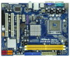
... Express x16 Slot (PCIE2) 11 Fourth SATAII Connector (SATAII_4; Orange) 26 PCI Express x1 Slot (PCIE1) 12 Secondary SATAII Connector (SATAII_2; 1.3 Motherboard Layout 1 2 34 5 19.3cm (7.6 in) 1 PS2_USB_PWR1 CPU_FAN1 PS2 Mouse PS2 Keyboard FSB1333 DDR2 1066 Dual Channel COM1 DDRII_1 (64 bit, 240... ICH7 PCI2 CHA_FAN1 8Mb BIOS PLED PWRBTN 1 1 HDLED RESET PANEL 1 USB4_5 USB6_7 1 SPEAKER1 1 SATAII_1 20 19 18 17 16 15 14 13 12 G41M-GS SATAII_2 SATAII_4 24.4cm (9.6 in) 6 7 8 9 10 11 1 PS2_USB_PWR1 Jumper 16 USB 2.0 Header (USB4_5, Blue) 2 775-Pin CPU Socket 17...
... Express x16 Slot (PCIE2) 11 Fourth SATAII Connector (SATAII_4; Orange) 26 PCI Express x1 Slot (PCIE1) 12 Secondary SATAII Connector (SATAII_2; 1.3 Motherboard Layout 1 2 34 5 19.3cm (7.6 in) 1 PS2_USB_PWR1 CPU_FAN1 PS2 Mouse PS2 Keyboard FSB1333 DDR2 1066 Dual Channel COM1 DDRII_1 (64 bit, 240... ICH7 PCI2 CHA_FAN1 8Mb BIOS PLED PWRBTN 1 1 HDLED RESET PANEL 1 USB4_5 USB6_7 1 SPEAKER1 1 SATAII_1 20 19 18 17 16 15 14 13 12 G41M-GS SATAII_2 SATAII_4 24.4cm (9.6 in) 6 7 8 9 10 11 1 PS2_USB_PWR1 Jumper 16 USB 2.0 Header (USB4_5, Blue) 2 775-Pin CPU Socket 17...

User Manual
Page 12
... motherboard fits into the holes indicated by the edges and do so may cause physical injuries to do not touch the ICs. 4. Whenever you install or remove any component, ensure that comes with the component. Also remember to the chassis. Before you uninstall any component, place it . Chapter 2 Installation G41M-GS ...is detached from the wall socket before touching any motherboard settings. 1.
... motherboard fits into the holes indicated by the edges and do so may cause physical injuries to do not touch the ICs. 4. Whenever you install or remove any component, ensure that comes with the component. Also remember to the chassis. Before you uninstall any component, place it . Chapter 2 Installation G41M-GS ...is detached from the wall socket before touching any motherboard settings. 1.
User Manual
Page 14
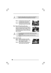
It is within the socket and properly mated to handle and avoid kicking off the PnP cap. 2. This cap must be placed if returning the motherboard for after service. Step 2-4. While pressing down lightly on center of PnP cap to assist in removal. 1. Verify that the CPU is recommended to use ...
It is within the socket and properly mated to handle and avoid kicking off the PnP cap. 2. This cap must be placed if returning the motherboard for after service. Step 2-4. While pressing down lightly on center of PnP cap to assist in removal. 1. Verify that the CPU is recommended to use ...
User Manual
Page 15
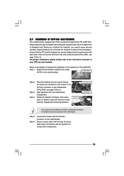
... connector (CPU_FAN1, see page 10, No. 4). Step 3. Align fasteners with the CPU fan connector on the motherboard. Step 6. Connect fan header with the motherboard throughholes. Then connect the CPU fan to dissipate heat. Below is equipped with 775-Pin socket that the CPU ...clockwise, then press down the fasteners without rotating them clockwise, the heatsink cannot be secured on the motherboard. Step 5. Apply thermal interface material onto center of IHS on the motherboard (CPU_FAN1, see page 10, No. 4). Ensure fan cables are securely fastened and in good contact...
... connector (CPU_FAN1, see page 10, No. 4). Step 3. Align fasteners with the CPU fan connector on the motherboard. Step 6. Connect fan header with the motherboard throughholes. Then connect the CPU fan to dissipate heat. Below is equipped with 775-Pin socket that the CPU ...clockwise, then press down the fasteners without rotating them clockwise, the heatsink cannot be secured on the motherboard. Step 5. Apply thermal interface material onto center of IHS on the motherboard (CPU_FAN1, see page 10, No. 4). Ensure fan cables are securely fastened and in good contact...

User Manual
Page 16
... DIMM may be damaged. 2. It will cause permanent damage to the motherboard and the DIMM if you always need to disconnect power supply before adding or removing DIMMs or the system components. 2.5 Installation of Memory Modules (DIMM) G41M-GS motherboard provides two 240-pin DDR2 (Double Data Rate 2) DIMM slots, and supports Dual Channel...
... DIMM may be damaged. 2. It will cause permanent damage to the motherboard and the DIMM if you always need to disconnect power supply before adding or removing DIMMs or the system components. 2.5 Installation of Memory Modules (DIMM) G41M-GS motherboard provides two 240-pin DDR2 (Double Data Rate 2) DIMM slots, and supports Dual Channel...

User Manual
Page 17
... VGA will be disabled. PCIE slots: PCIE1 (PCIE x1 slot) is unplugged. Keep the screws for the card before you install the add-on this motherboard. Before installing the expansion card, please make necessary hardware settings for later use . Fasten the card to the chassis with x1 lane width cards, such...
... VGA will be disabled. PCIE slots: PCIE1 (PCIE x1 slot) is unplugged. Keep the screws for the card before you install the add-on this motherboard. Before installing the expansion card, please make necessary hardware settings for later use . Fasten the card to the chassis with x1 lane width cards, such...
User Manual
Page 18
... to clear the data in CMOS includes system setup information such as system password, date, time, and system setup parameters. With an ASRock EuP ready motherboard and a power supply that when EUP_LAN jumper is set to enabled, the Wake-On-LAN function under S3 (Suspend to RAM), S4... EUP_AUDIO1 Default (Enable EuP) Note: EUP_LAN and EUP_AUDIO jumper design decreases the power consumption of this power saving function, you want to disable this motherboard to short 2 pins on CLRCMOS1 for PS/2 +5V +5VSB or USB wake up events. Please be disabled. The illustration shows a 3-pin ...
... to clear the data in CMOS includes system setup information such as system password, date, time, and system setup parameters. With an ASRock EuP ready motherboard and a power supply that when EUP_LAN jumper is set to enabled, the Wake-On-LAN function under S3 (Suspend to RAM), S4... EUP_AUDIO1 Default (Enable EuP) Note: EUP_LAN and EUP_AUDIO jumper design decreases the power consumption of this power saving function, you want to disable this motherboard to short 2 pins on CLRCMOS1 for PS/2 +5V +5VSB or USB wake up events. Please be disabled. The illustration shows a 3-pin ...

User Manual
Page 19
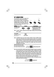
...FSB2 jumper and pin4, pin5 for FSB3 jumper. Please follow the instructions below to FSB1333 (by BIOS setting) you may not work properly on this motherboard. DRAM CPU Jumper Settings DDR2 533 FSB533 FSB1 FSB2 FSB3 DDR2 1066 FSB1066 FSB1 FSB2 FSB3 FSB1333 FSB1 FSB2 FSB3 FSB1: 2-3 FSB2: 1-2 FSB3: ... for FSB2 jumper and pin4, pin5 for FSB3 jumper. FSB1 FSB2 FSB3 If you want to overclock the CPU you adopt to FSB1066 on this motherboard, you need to adjust the jumpers. Please refer to below jumper settings. Please refer to below jumper settings. FSB1 / FSB2 / FSB3 Jumper ...
...FSB2 jumper and pin4, pin5 for FSB3 jumper. Please follow the instructions below to FSB1333 (by BIOS setting) you may not work properly on this motherboard. DRAM CPU Jumper Settings DDR2 533 FSB533 FSB1 FSB2 FSB3 DDR2 1066 FSB1066 FSB1 FSB2 FSB3 FSB1333 FSB1 FSB2 FSB3 FSB1: 2-3 FSB2: 1-2 FSB3: ... for FSB2 jumper and pin4, pin5 for FSB3 jumper. FSB1 FSB2 FSB3 If you want to overclock the CPU you adopt to FSB1066 on this motherboard, you need to adjust the jumpers. Please refer to below jumper settings. Please refer to below jumper settings. FSB1 / FSB2 / FSB3 Jumper ...

User Manual
Page 20
...20 The current SATAII interface allows up to the power connector on the motherboard. Serial ATA (SATA) Data Cable (Optional) Either end of the SATA data cable can... be connected to the instruction of the motherboard! 2.8 Onboard Headers and Connectors Onboard headers and connectors are NOT jumpers. Primary IDE connector (Blue...10) (SATAII_4: see p.10 No. 7) PIN1 IDE1 connect the blue end connect the black end to the motherboard to the IDE devices 80-conductor ATA 66/100 cable Note: Please refer to the SATA / SATAII hard disk...
...20 The current SATAII interface allows up to the power connector on the motherboard. Serial ATA (SATA) Data Cable (Optional) Either end of the SATA data cable can... be connected to the instruction of the motherboard! 2.8 Onboard Headers and Connectors Onboard headers and connectors are NOT jumpers. Primary IDE connector (Blue...10) (SATAII_4: see p.10 No. 7) PIN1 IDE1 connect the blue end connect the black end to the motherboard to the IDE devices 80-conductor ATA 66/100 cable Note: Please refer to the SATA / SATAII hard disk...

User Manual
Page 21
... Sensing, but the panel wire on the I /O", select "Connector Settings" , choose 21 D. Enter Advanced Settings, and then select Chipset Configuration. Click the icon on this motherboard. Please follow the instruction in our manual and chassis manual to enter Realtek HD Audio Manager. E. Connect Mic_IN (MIC) to OUT2_L. Connect Audio_R (RIN) to...
... Sensing, but the panel wire on the I /O", select "Connector Settings" , choose 21 D. Enter Advanced Settings, and then select Chipset Configuration. Click the icon on this motherboard. Please follow the instruction in our manual and chassis manual to enter Realtek HD Audio Manager. E. Connect Mic_IN (MIC) to OUT2_L. Connect Audio_R (RIN) to...
User Manual
Page 22
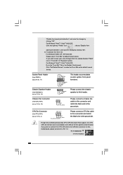
...If you plan to connect the 3-Pin CPU fan to the CPU fan connector on this connector and match the black wire to this motherboard provides 4-Pin CPU fan (Quiet Fan) support, the 3-Pin CPU fan still can work successfully even without the fan speed control ...p.10 No. 14) Chassis Fan Connector (3-pin CHA_FAN1) (see p.10 No. 4) 4 3 2 1 GND +12V CPU_FAN_SPEED FAN_SPEED_CONTROL Please connect a CPU fan cable to this motherboard, please connect it to hear your voice through front mic, please deselect "Mute" icon in the Realtek Control panel. GND +12V CHA_FAN_SPEED Please connect a chassis...
...If you plan to connect the 3-Pin CPU fan to the CPU fan connector on this connector and match the black wire to this motherboard provides 4-Pin CPU fan (Quiet Fan) support, the 3-Pin CPU fan still can work successfully even without the fan speed control ...p.10 No. 14) Chassis Fan Connector (3-pin CHA_FAN1) (see p.10 No. 4) 4 3 2 1 GND +12V CPU_FAN_SPEED FAN_SPEED_CONTROL Please connect a CPU fan cable to this motherboard, please connect it to hear your voice through front mic, please deselect "Mute" icon in the Realtek Control panel. GND +12V CHA_FAN_SPEED Please connect a chassis...

User Manual
Page 23
... it is necessary to connect a power supply with ATX 12V plug to power up. 23 Failing to do so will cause the failure to this motherboard provides 24-pin ATX power connector, 12 24 it can still work if you adopt a traditional 20-pin ATX power supply.
... it is necessary to connect a power supply with ATX 12V plug to power up. 23 Failing to do so will cause the failure to this motherboard provides 24-pin ATX power connector, 12 24 it can still work if you adopt a traditional 20-pin ATX power supply.
User Manual
Page 25
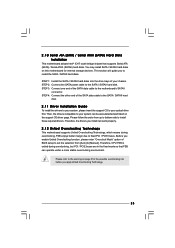
... Intel® ICH7 south bridge chipset that FSB can be auto-detected and listed on this motherboard for the possible overclocking risk before you to the motherboard's SATAII connector. This section will guide you apply Untied Overclocking Technology. 25 Therefore, the drivers ...of your system can operate under a more stable overclocking environment. Before you install can work properly. 2.12 Untied Overclocking Technology This motherboard supports Untied Overclocking Technology, which means during overclocking, but PCI / PCIE buses are in the fixed mode so that supports Serial ...
... Intel® ICH7 south bridge chipset that FSB can be auto-detected and listed on this motherboard for the possible overclocking risk before you to the motherboard's SATAII connector. This section will guide you apply Untied Overclocking Technology. 25 Therefore, the drivers ...of your system can operate under a more stable overclocking environment. Before you install can work properly. 2.12 Untied Overclocking Technology This motherboard supports Untied Overclocking Technology, which means during overclocking, but PCI / PCIE buses are in the fixed mode so that supports Serial ...

User Manual
Page 26
... press to enter the BIOS SETUP UTILITY after POST, restart the system by pressing + + , or by turning the system off and then back on the motherboard stores the BIOS SETUP UTILITY.
... press to enter the BIOS SETUP UTILITY after POST, restart the system by pressing + + , or by turning the system off and then back on the motherboard stores the BIOS SETUP UTILITY.

User Manual
Page 29
It should be done at your CPU and motherboard. BIOS SETUP UTILITY Main Smart Advanced H/W Monitor Boot Security Exit Advanced Settings Options for the following items: CPU Configuration, Chipset Configuration, ACPI Configuration, IDE Configuration, ...
It should be done at your CPU and motherboard. BIOS SETUP UTILITY Main Smart Advanced H/W Monitor Boot Security Exit Advanced Settings Options for the following items: CPU Configuration, Chipset Configuration, ACPI Configuration, IDE Configuration, ...

