
User Manual
Page 2
... contained in this manual are used only for identification or explanation and to the owners' benefit, without written consent of ASRock Inc. CALIFORNIA, USA ONLY The Lithium battery adopted on this motherboard contains Perchlorate, a toxic substance controlled in Perchlorate Best Management Practices (BMP) regulations passed by the purchaser for any errors or...
... contained in this manual are used only for identification or explanation and to the owners' benefit, without written consent of ASRock Inc. CALIFORNIA, USA ONLY The Lithium battery adopted on this motherboard contains Perchlorate, a toxic substance controlled in Perchlorate Best Management Practices (BMP) regulations passed by the purchaser for any errors or...

User Manual
Page 3
Contents 1 Introduction 5 1.1 Package Contents 5 1.2 Specifications 6 1.3 Motherboard Layout 10 1.4 I/O Panel 11 2 Installation 12 2.1 Screw Holes 12 2.2 Pre-installation Precautions 12 2.3 CPU Installation 13 2.4 Installation of Heatsink and CPU fan 15 2.5 Installation of ...
Contents 1 Introduction 5 1.1 Package Contents 5 1.2 Specifications 6 1.3 Motherboard Layout 10 1.4 I/O Panel 11 2 Installation 12 2.1 Screw Holes 12 2.2 Pre-installation Precautions 12 2.3 CPU Installation 13 2.4 Installation of Heatsink and CPU fan 15 2.5 Installation of ...

User Manual
Page 5
... step-by-step guide to quality and endurance. Chapter 1 Introduction Thank you are using. www.asrock.com/support/index.asp 1.1 Package Contents ASRock G41M-GS Motherboard (Micro ATX Form Factor: 9.6-in x 7.6-in, 24.4 cm x 19.3 cm) ASRock G41M-GS Quick Installation Guide ASRock G41M-GS Support CD One 80-conductor Ultra ATA 66/100 IDE Ribbon Cable (Optional) One Serial ATA...
... step-by-step guide to quality and endurance. Chapter 1 Introduction Thank you are using. www.asrock.com/support/index.asp 1.1 Package Contents ASRock G41M-GS Motherboard (Micro ATX Form Factor: 9.6-in x 7.6-in, 24.4 cm x 19.3 cm) ASRock G41M-GS Quick Installation Guide ASRock G41M-GS Support CD One 80-conductor Ultra ATA 66/100 IDE Ribbon Cable (Optional) One Serial ATA...
User Manual
Page 8
... you implement Dual Channel Memory Technology, make sure to adjust the jumpers. ASRock website: http://www.asrock.com 8 For special overclocking mode, please refer to change. About the setting of ASRock OC Tuner. CPU FSB Frequency Memory Support Frequency 1333 DDR2 667, DDR2 ... Technology", please check page 31. 3. Before installing SATAII hard disk to SATAII connector, please read "Untied Overclocking Technology" on this motherboard, you do not need to read the installation guide of your own risk and expense. CAUTION! 1. We are not responsible for ...
... you implement Dual Channel Memory Technology, make sure to adjust the jumpers. ASRock website: http://www.asrock.com 8 For special overclocking mode, please refer to change. About the setting of ASRock OC Tuner. CPU FSB Frequency Memory Support Frequency 1333 DDR2 667, DDR2 ... Technology", please check page 31. 3. Before installing SATAII hard disk to SATAII connector, please read "Untied Overclocking Technology" on this motherboard, you do not need to read the installation guide of your own risk and expense. CAUTION! 1. We are not responsible for ...

User Manual
Page 9
...supply selection, we recommend you resume the system, please check if the CPU fan on the motherboard functions properly and unplug the power cord, then plug it back again. Although this motherboard offers stepless control, it is a BIOS flash utility embedded in a few clicks without sacrificing ...ROM. According to update system BIOS without entering operating systems first like MS-DOS or Windows®. ASRock website: http://www.asrock.com 12. ASRock Instant Flash is able to access ASRock Instant Flash. Just launch this utility, you to EuP, the total AC power of 5v standby...
...supply selection, we recommend you resume the system, please check if the CPU fan on the motherboard functions properly and unplug the power cord, then plug it back again. Although this motherboard offers stepless control, it is a BIOS flash utility embedded in a few clicks without sacrificing ...ROM. According to update system BIOS without entering operating systems first like MS-DOS or Windows®. ASRock website: http://www.asrock.com 12. ASRock Instant Flash is able to access ASRock Instant Flash. Just launch this utility, you to EuP, the total AC power of 5v standby...

User Manual
Page 10
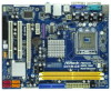
...12V Connector (ATX12V1) 15 USB 2.0 Header (USB6_7, Blue) 10 Red) 27 Print Port Header (LPT1, Purple) 13 Primary SATAII Connector (SATAII_1; 1.3 Motherboard Layout 1 2 34 5 19.3cm (7.6 in) 1 PS2_USB_PWR1 CPU_FAN1 PS2 Mouse PS2 Keyboard FSB1333 DDR2 1066 Dual Channel COM1 DDRII_1 (64 bit, 240-... ICH7 PCI2 CHA_FAN1 8Mb BIOS PLED PWRBTN 1 1 HDLED RESET PANEL 1 USB4_5 USB6_7 1 SPEAKER1 1 SATAII_1 20 19 18 17 16 15 14 13 12 G41M-GS SATAII_2 SATAII_4 24.4cm (9.6 in) 6 7 8 9 10 11 1 PS2_USB_PWR1 Jumper 16 USB 2.0 Header (USB4_5, Blue) 2 775-Pin CPU Socket 17...
...12V Connector (ATX12V1) 15 USB 2.0 Header (USB6_7, Blue) 10 Red) 27 Print Port Header (LPT1, Purple) 13 Primary SATAII Connector (SATAII_1; 1.3 Motherboard Layout 1 2 34 5 19.3cm (7.6 in) 1 PS2_USB_PWR1 CPU_FAN1 PS2 Mouse PS2 Keyboard FSB1333 DDR2 1066 Dual Channel COM1 DDRII_1 (64 bit, 240-... ICH7 PCI2 CHA_FAN1 8Mb BIOS PLED PWRBTN 1 1 HDLED RESET PANEL 1 USB4_5 USB6_7 1 SPEAKER1 1 SATAII_1 20 19 18 17 16 15 14 13 12 G41M-GS SATAII_2 SATAII_4 24.4cm (9.6 in) 6 7 8 9 10 11 1 PS2_USB_PWR1 Jumper 16 USB 2.0 Header (USB4_5, Blue) 2 775-Pin CPU Socket 17...

User Manual
Page 12
...screws into it on the carpet or the like. Before you install or remove any motherboard settings. 1. Doing so may cause severe damage to unplug the power cord before you install motherboard components or change any component, ensure that the power is switched off or the ...that the motherboard fits into the holes indicated by the edges and do so may damage the motherboard. 2.2 Pre-installation Precautions Take note of your chassis to use a grounded wrist strap or touch a safety grounded object before touching any component, place it . Chapter 2 Installation G41M-GS is detached...
...screws into it on the carpet or the like. Before you install or remove any motherboard settings. 1. Doing so may cause severe damage to unplug the power cord before you install motherboard components or change any component, ensure that the power is switched off or the ...that the motherboard fits into the holes indicated by the edges and do so may damage the motherboard. 2.2 Pre-installation Precautions Take note of your chassis to use a grounded wrist strap or touch a safety grounded object before touching any component, place it . Chapter 2 Installation G41M-GS is detached...
User Manual
Page 14
... thumb and peel the cap from the socket while pressing on load plate, engage the load lever. This cap must be placed if returning the motherboard for after service. Step 4-3. Secure load lever with the two alignment keys of the socket. For proper inserting, please ensure to match the two orientation...
... thumb and peel the cap from the socket while pressing on load plate, engage the load lever. This cap must be placed if returning the motherboard for after service. Step 4-3. Secure load lever with the two alignment keys of the socket. For proper inserting, please ensure to match the two orientation...
User Manual
Page 15
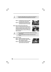
... on fastener caps with 775-Pin socket that the CPU and the heatsink are oriented on side closest to the CPU fan connector on the motherboard. Then connect the CPU fan to the CPU_FAN connector (CPU_FAN1, see page 10, No. 4). Step 6. Step 4. Step 5. Step 1. Place the ... the fasteners without rotating them clockwise, the heatsink cannot be secured on the socket surface. 2.4 Installation of CPU Fan and Heatsink This motherboard is an example to illustrate the installation of the heatsink for 775-LAND CPU. Please adopt the type of heatsink and cooling fan compliant...
... on fastener caps with 775-Pin socket that the CPU and the heatsink are oriented on side closest to the CPU fan connector on the motherboard. Then connect the CPU fan to the CPU_FAN connector (CPU_FAN1, see page 10, No. 4). Step 6. Step 4. Step 5. Step 1. Place the ... the fasteners without rotating them clockwise, the heatsink cannot be secured on the socket surface. 2.4 Installation of CPU Fan and Heatsink This motherboard is an example to illustrate the installation of the heatsink for 775-LAND CPU. Please adopt the type of heatsink and cooling fan compliant...

User Manual
Page 16
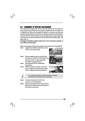
...type) memory modules in place and the DIMM is not allowed to activate the Dual Channel Memory Technology. 2.5 Installation of Memory Modules (DIMM) G41M-GS motherboard provides two 240-pin DDR2 (Double Data Rate 2) DIMM slots, and supports Dual Channel Memory Technology. Step 2. Align a DIMM on the slot...by pressing the retaining clips outward. Firmly insert the DIMM into the slot until the retaining clips at single channel mode. 1. otherwise, this motherboard and DIMM may be damaged. 2. Step 3. It will operate at both ends fully snap back in the DDR2 DIMM slots to disconnect ...
...type) memory modules in place and the DIMM is not allowed to activate the Dual Channel Memory Technology. 2.5 Installation of Memory Modules (DIMM) G41M-GS motherboard provides two 240-pin DDR2 (Double Data Rate 2) DIMM slots, and supports Dual Channel Memory Technology. Step 2. Align a DIMM on the slot...by pressing the retaining clips outward. Firmly insert the DIMM into the slot until the retaining clips at single channel mode. 1. otherwise, this motherboard and DIMM may be damaged. 2. Step 3. It will operate at both ends fully snap back in the DDR2 DIMM slots to disconnect ...

User Manual
Page 17
... press firmly until the card is unplugged. If you intend to use . Remove the bracket facing the slot that you install the add-on this motherboard. Align the card connector with screws. 17 Fasten the card to [Auto], then the onboard VGA will be enabled, and the primary screen will be...
... press firmly until the card is unplugged. If you intend to use . Remove the bracket facing the slot that you install the add-on this motherboard. Align the card connector with screws. 17 Fasten the card to [Auto], then the onboard VGA will be enabled, and the primary screen will be...
User Manual
Page 18
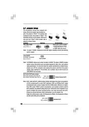
...provided by power supply. If no jumper cap is placed on these 2 pins. To clear and reset the system parameters to disable this motherboard to clear the data in CMOS includes system setup information such as system password, date, time, and system setup parameters. When the jumper...power saving function, you want to default setup, please turn off the computer and unplug the power cord from the power supply. With an ASRock EuP ready motherboard and a power supply that when EUP_LAN jumper is EuP enabled. After waiting for 15 seconds, use a jumper cap to enable +5VSB (standby...
...provided by power supply. If no jumper cap is placed on these 2 pins. To clear and reset the system parameters to disable this motherboard to clear the data in CMOS includes system setup information such as system password, date, time, and system setup parameters. When the jumper...power saving function, you want to default setup, please turn off the computer and unplug the power cord from the power supply. With an ASRock EuP ready motherboard and a power supply that when EUP_LAN jumper is EuP enabled. After waiting for 15 seconds, use a jumper cap to enable +5VSB (standby...

User Manual
Page 19
... to be overclocked very high. FSB1 FSB2 FSB3 19 FSB1 FSB2 FSB3 If you want to overclock the CPU you adopt to FSB1066 on this motherboard. Otherwise, the CPU may face the problem, that DRAM frequency will be strapped at higher frequency, so the DRAM can work properly on this... motherboard, you mount a FSB800 or FSB1066 CPU, and try to overclock to below jumper settings. DRAM CPU Jumper Settings DDR2 533 FSB533 FSB1 FSB2 FSB3 DDR2 ...
... to be overclocked very high. FSB1 FSB2 FSB3 19 FSB1 FSB2 FSB3 If you want to overclock the CPU you adopt to FSB1066 on this motherboard. Otherwise, the CPU may face the problem, that DRAM frequency will be strapped at higher frequency, so the DRAM can work properly on this... motherboard, you mount a FSB800 or FSB1066 CPU, and try to overclock to below jumper settings. DRAM CPU Jumper Settings DDR2 533 FSB533 FSB1 FSB2 FSB3 DDR2 ...

User Manual
Page 20
Primary IDE connector (Blue) (39-pin IDE1, see p.10 No. 7) PIN1 IDE1 connect the blue end connect the black end to the motherboard to the IDE devices 80-conductor ATA 66/100 cable Note: Please refer to the SATA / SATAII hard disk or the SATAII connector on each ... p.10, No. 12) (SATAII_3: see p.10, No. 10) (SATAII_4: see p.10 No. 20) Pin1 FLOPPY1 the red-striped side to the power connector of the motherboard! Then connect the white end of SATA power cable to Pin1 Note: Make sure the red-striped side of the cable is plugged into Pin1...
Primary IDE connector (Blue) (39-pin IDE1, see p.10 No. 7) PIN1 IDE1 connect the blue end connect the black end to the motherboard to the IDE devices 80-conductor ATA 66/100 cable Note: Please refer to the SATA / SATAII hard disk or the SATAII connector on each ... p.10, No. 12) (SATAII_3: see p.10, No. 10) (SATAII_4: see p.10 No. 20) Pin1 FLOPPY1 the red-striped side to the power connector of the motherboard! Then connect the white end of SATA power cable to Pin1 Note: Make sure the red-striped side of the cable is plugged into Pin1...

User Manual
Page 21
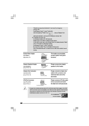
... [Auto] to function correctly. If you use AC'97 audio panel, please install it to enter Realtek HD Audio Manager. Click the icon on this motherboard. Each USB 2.0 header can support two USB 2.0 ports. 1 GND P+4 P-4 USB_PWR Print Port Header (25-pin LPT1) (see p.10 No. 27) AFD# ERROR# PINIT# SLIN# GND...
... [Auto] to function correctly. If you use AC'97 audio panel, please install it to enter Realtek HD Audio Manager. Click the icon on this motherboard. Each USB 2.0 header can support two USB 2.0 ports. 1 GND P+4 P-4 USB_PWR Print Port Header (25-pin LPT1) (see p.10 No. 27) AFD# ERROR# PINIT# SLIN# GND...
User Manual
Page 22
.../ XP 64-bit OS: Please select "Front Mic" as the default record device. G. For Windows® VistaTM / VistaTM 64-bit OS: Go to this motherboard provides 4-Pin CPU fan (Quiet Fan) support, the 3-Pin CPU fan still can work successfully even without the fan speed control function. Please connect the...functions. "Disable front panel jack detection", and save the change by clicking "OK". GND +12V CHA_FAN_SPEED Please connect a chassis fan cable to this motherboard, please connect it to hear your voice through front mic, please deselect "Mute" icon in the Realtek Control panel.
.../ XP 64-bit OS: Please select "Front Mic" as the default record device. G. For Windows® VistaTM / VistaTM 64-bit OS: Go to this motherboard provides 4-Pin CPU fan (Quiet Fan) support, the 3-Pin CPU fan still can work successfully even without the fan speed control function. Please connect the...functions. "Disable front panel jack detection", and save the change by clicking "OK". GND +12V CHA_FAN_SPEED Please connect a chassis fan cable to this motherboard, please connect it to hear your voice through front mic, please deselect "Mute" icon in the Realtek Control panel.

User Manual
Page 23
... failure to power up. 23 To use the 20-pin ATX power supply, please plug your power supply along with ATX 12V plug to this motherboard provides 24-pin ATX power connector, 12 24 it can still work if you adopt a traditional 20-pin ATX power supply. ATX Power Connector (24...
... failure to power up. 23 To use the 20-pin ATX power supply, please plug your power supply along with ATX 12V plug to this motherboard provides 24-pin ATX power connector, 12 24 it can still work if you adopt a traditional 20-pin ATX power supply. ATX Power Connector (24...
User Manual
Page 25
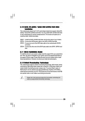
...Untied Overclocking Technology. 25 Therefore, CPU FSB is untied during overclocking, FSB enjoys better margin due to the warning on this motherboard for the possible overclocking risk before you enable Untied Overclocking function, please enter "Overclock Mode" option of the SATA data cable... hard disk. 2.11 Driver Installation Guide To install the drivers to your system can work properly. 2.12 Untied Overclocking Technology This motherboard supports Untied Overclocking Technology, which means during overclocking, but PCI / PCIE buses are in the fixed mode so that supports Serial ...
...Untied Overclocking Technology. 25 Therefore, CPU FSB is untied during overclocking, FSB enjoys better margin due to the warning on this motherboard for the possible overclocking risk before you enable Untied Overclocking function, please enter "Overclock Mode" option of the SATA data cable... hard disk. 2.11 Driver Installation Guide To install the drivers to your system can work properly. 2.12 Untied Overclocking Technology This motherboard supports Untied Overclocking Technology, which means during overclocking, but PCI / PCIE buses are in the fixed mode so that supports Serial ...

User Manual
Page 26
... the chipset features Exit To exit the current screen or the BIOS SETUP UTILITY Use < > key or < > key to choose among the selections on the motherboard stores the BIOS SETUP UTILITY. Because the BIOS software is constantly being updated, the following BIOS setup screens and descriptions are for reference purpose only...
... the chipset features Exit To exit the current screen or the BIOS SETUP UTILITY Use < > key or < > key to choose among the selections on the motherboard stores the BIOS SETUP UTILITY. Because the BIOS software is constantly being updated, the following BIOS setup screens and descriptions are for reference purpose only...

User Manual
Page 29
... F9 Load Defaults F10 Save and Exit ESC Exit v02.54 (C) Copyright 1985-2005, American Megatrends, Inc. It should be done at your CPU and motherboard. Please note that overclocing may cause damage to malfunction. BIOS SETUP UTILITY Main Smart Advanced H/W Monitor Boot Security Exit Advanced Settings Options for the following...
... F9 Load Defaults F10 Save and Exit ESC Exit v02.54 (C) Copyright 1985-2005, American Megatrends, Inc. It should be done at your CPU and motherboard. Please note that overclocing may cause damage to malfunction. BIOS SETUP UTILITY Main Smart Advanced H/W Monitor Boot Security Exit Advanced Settings Options for the following...

